Chapter 2
2-9
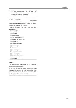
2.2
Adjustment at Time of
Parts Replacement
2.2.1
Overview
0003-8360
Make the appropriate adjustments whenever you have
replaced the following major parts:
・
reader controller PCB (i.e., after EEPROM
initialization)
[1]sensor output
[2]tray width
[3]magnification
[4]horizontal registration
[5]leading edge registration
[6]white level
・
Post-separation sensor
[1]sensor output
・
Read sensor
[1]sensor output
・
Post-separation sensor
[1]sensor output
・
Original detecting volume
[1]tray width
Memo:
For details of these adjustments, see the instructions
given for basic adjustments.
If you have replaced the reader controller PCB (or
initialized EEPROM), see the descriptions given
under "After Replacing the Reader Controller PCB"
on the host machine service manual.
Summary of Contents for DADF-M1
Page 1: ...Feb 21 2005 Portable Manual Feeder DADF M1 ...
Page 2: ......
Page 6: ......
Page 9: ...Chapter 1 Maintenance and Inspection ...
Page 10: ......
Page 12: ......
Page 26: ...Chapter 1 1 14 F 1 20 F 1 21 4 Clean the top face plastic film 1 of the prism 1 2 1 ...
Page 31: ...Chapter 2 Standards and Adjustments ...
Page 32: ......
Page 34: ......
Page 44: ......
Page 45: ...Chapter 3 Error Code ...
Page 46: ......
Page 47: ...Contents Contents 3 1 User Error Code 3 1 3 1 1 Alarm Code 3 1 ...
Page 48: ......
Page 50: ......
Page 51: ...Chapter 4 Outline of Components ...
Page 52: ......
Page 54: ......
Page 59: ...Chapter 5 System Construction ...
Page 60: ......
Page 62: ......
Page 69: ...Feb 21 2005 ...
Page 70: ......

