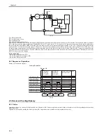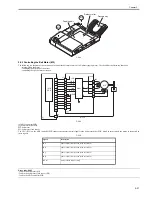
Chapter 2
2-6
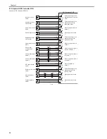
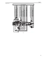
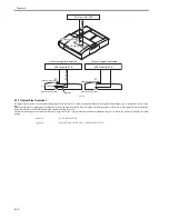
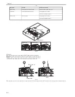
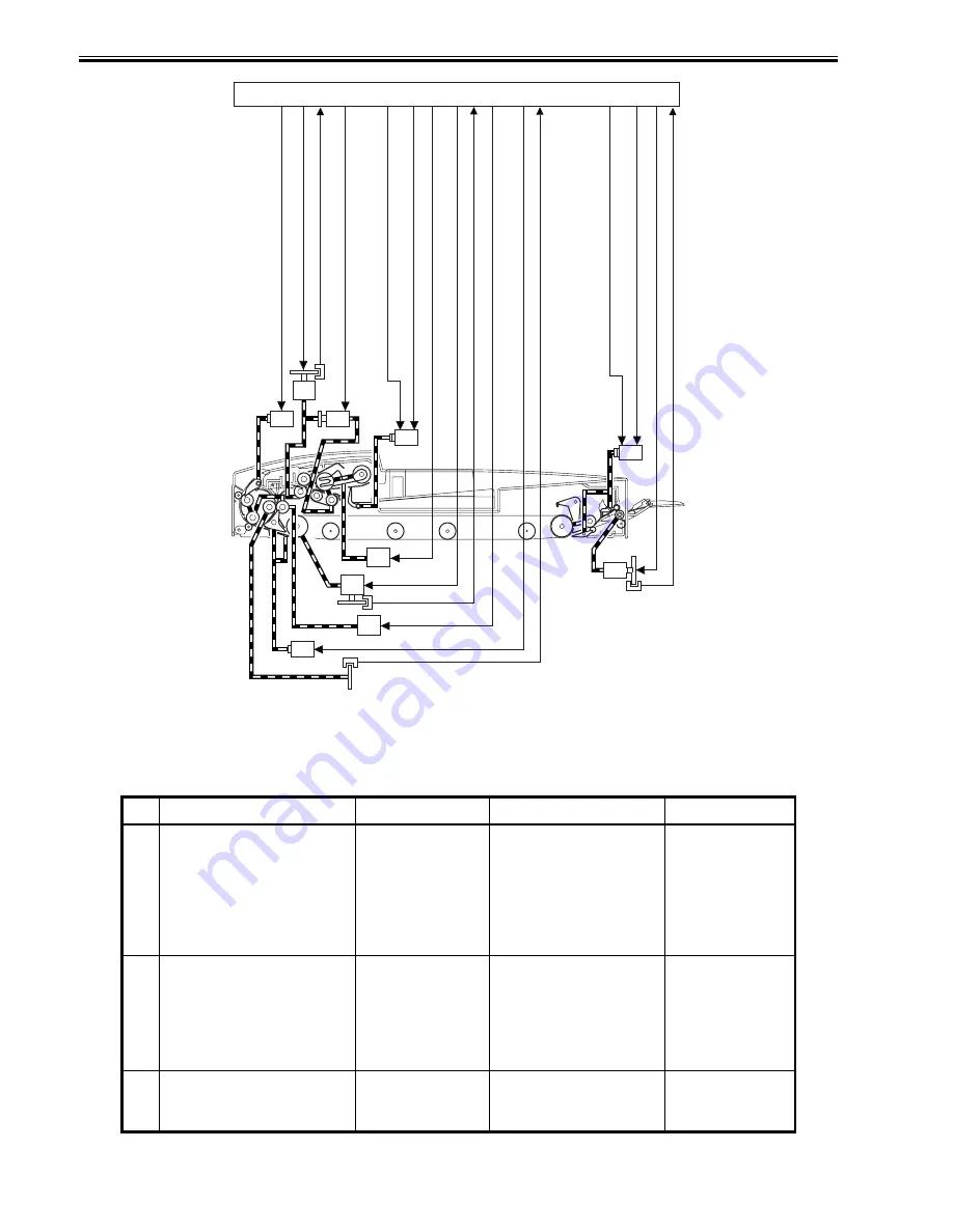
Sensor Arrangement
F-2-6
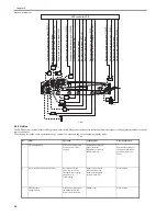
2.2.2 Outline
0011-2233
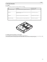
The DADF operates in either of the following three modes; the DADF operates in response to instructions from the copier, executing appropriate modes to suit the
copier's operations.
The following table shows each operation mode, an outline of its operation, and its corresponding copying mode:
T-2-1
No.
Mode
Operation
Copying mode
Copying operation
1
CW pickup/delivery
Picks up an original, and
delivers it as it is after
copying.
Single-sided original to
single-sided copy
Signal-sided original to
double-sided copy
Stream reading (fixed if
the reproduction ratio is
not between 50% and
200%)
2
Pre-reversal pickup/reversal/ delivery
Reverses an original,
picks it up, reverses it
once again after copying,
and delivers it.
Fixed reading
Double-sided original
to double-sided copy
Double-sided original
to single-sided copy
Fixed reading
3
Manual feeder
pickup/delivery
Picks up an original from
the manual feeder, and
delivers it after copying.
Manual copy
Fixed reading
PI 2
PI 1
PI 5
PI 11
SL3
SL1
SL2
SL4
M5
P
re
-r
e
v
e
rsal
solenoid
drive
s
ig
n
a
l
(SL1D)
Se
p
a
ration
motor
c
lock
signal
(S
PCLK
)
Se
paration
motor
d
riv
e
s
ig
n
a
l
Se
p
a
ration
clutch
drive
signal
(C
L
D
)
Stoppe
r
s
o
le
n
o
id
d
ri
v
e
s
ig
n
a
l
2
(S
L
2
D
2
)
S
to
p
p
e
r
p
late
s
olenoid
signal
1
(S
L
2D1
)
Pickup
mo
to
r
d
ri
v
e
s
ig
n
a
l
Be
lt
m
o
tor
d
rive
signal
Be
lt
m
o
tor
c
lock
signal
(BTC
L
K
)
Re
v
e
rs
al
m
o
tor
d
rive
s
ignal
Re
v
e
rs
al
solenoid
drive
s
ignal
(S
L
3D
)
Re
gistration
roller
clock
s
ignal
(T
RCLK
)
Deliv
e
ry
solenoid
drive
s
ign
a
l
1
(S
L
4
D
)
Deliv
e
ry
motor
d
rive
signal
Deliv
e
ry
m
o
tor
clock
s
ignal
(E
J
C
L
K
)
CL
Deliv
e
ry
solenoid
drive
s
ign
a
l
1
(S
L
4
D
)
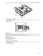
ADF controller PCB
M2
M3
M4
M1
Summary of Contents for DADF-Q1
Page 1: ...Aug 24 2007 Service Manual Feeder DADF Q1 ...
Page 2: ......
Page 6: ......
Page 11: ...Chapter 1 Specifications ...
Page 12: ......
Page 14: ......
Page 18: ......
Page 19: ...Chapter 2 Functions ...
Page 20: ......
Page 22: ......
Page 75: ...Chapter 3 Parts Replacement Procedure ...
Page 76: ......
Page 107: ...Chapter 4 Maintenance ...
Page 108: ......
Page 149: ...Chapter 5 Error Code ...
Page 150: ......
Page 152: ......
Page 154: ......
Page 155: ...Aug 24 2007 ...
Page 156: ......


