Chapter 2
2-22
2.5.3 Controlling the Delivery Motor (M5)
0011-2388
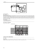
The following is a diagram of the circuit used to control the delivery motor (M5), which is a DC motor. The circuit has the following functions:
- turning on/off the motor
- controlling the speed of motor rotation
F-2-35
[1] ADF controller PCB
M5: delivery motor
PI11: delivery motor clock sensor
The CPU (IC18) on the ADF controller PCB sends the motor rotation speed signal (EJMPWM*) to the drive control block, which in turn generates the motor drive
signal (EJMD*) in keeping with the arriving signal.
The rotation of the motor generates the motor rotation signal (EJCLK), used by the CPU to monitor the operation of the motor.
T-2-11
Error code: E404
- fault in the delivery motor (M5)
- fault in the delivery motor clock sensor (PI11)
- fault in the ADF controller PCB
- Related adjustment -
sensor/delivery motor adjustment: when replacing the delivery motor
2.6 Feeding Unit
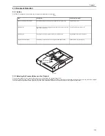
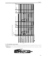
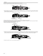
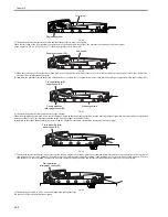
2.6.1 Outline of CW Pickup/Delivery
0011-7302
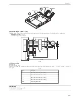
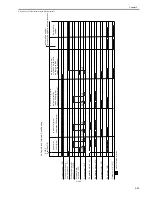
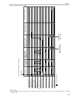
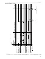
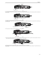
The machine uses CW pickup/delivery both in fixed reading mode and in stream reading mode.
T-2-12
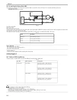
The machine uses fixed reading mode for the following:
- the magnification is set to 201% or higher.
- the machine has identified the original as being of a non-default size.
- Stream reading is disabled in the host machine's service mode (FEEDER> OPTION> DOC-F-SW).
- the host machine has detected soiling of the copyboard glass.
Signal
Description
EJMPWM *
motor rotation speed control
EJMD *
motor operation drive control
EJCLK
motor operation monitoring
Operation
Mode of operation
Printing mode
Printing mode
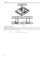
fixed reading
single-sided original -> singal-sided print
(magnification: between 201% and 400%)
single-sided original -> double-sided print
(magnification: between 201% and 400%)
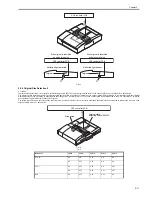
stream reading
single-sided original -> singl-sided print
(magnification: between 25% and 200%)
single-sided original -> double-sided print
(magnification: between 25% and 200%)
+3.3v
+24R
M5
Q19
Q20
IC7
J2
J3
IC18
CPU
EJMD*
EJMPWM*
PI 11
EJCLK
EJCLK
11
12
2
[1]
Summary of Contents for DADF-Q1
Page 1: ...Aug 24 2007 Service Manual Feeder DADF Q1 ...
Page 2: ......
Page 6: ......
Page 11: ...Chapter 1 Specifications ...
Page 12: ......
Page 14: ......
Page 18: ......
Page 19: ...Chapter 2 Functions ...
Page 20: ......
Page 22: ......
Page 75: ...Chapter 3 Parts Replacement Procedure ...
Page 76: ......
Page 107: ...Chapter 4 Maintenance ...
Page 108: ......
Page 149: ...Chapter 5 Error Code ...
Page 150: ......
Page 152: ......
Page 154: ......
Page 155: ...Aug 24 2007 ...
Page 156: ......

