background image

Instruction Manual

Digital Cinema Camera

PUB. DIE-0441-001

COP

Y

Summary of Contents for EOS C500

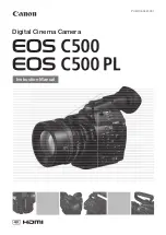
Page 1: ...Instruction Manual Digital Cinema Camera PUB DIE 0441 001 COPY ...

Page 2: ...tions However there is no guarantee that interference will not occur in a particular installation If this equipment does cause harmful interference to radio or television reception which can be determined by turning the equipment off and on the user is encouraged to try to correct the interference by one or more of the following measures Reorient or relocate the receiving antenna Increase the sepa...

Page 3: ...environment and human health due to potentially hazardous substances that are generally associated with EEE Your cooperation in the correct disposal of this product will contribute to the effective usage of natural resources For more information about the recycling of this product please contact your local city office waste authority approved scheme or your household waste disposal service or visi...

Page 4: ...pparatus the apparatus has been exposed to rain or moisture does not operate normally or has been dropped Trademark Acknowledgements SD and SDHC Logos are trademarks of SD 3C LLC CompactFlash is a trademark of SanDisk Corporation The CF Logo is a trademark of CompactFlash Association Microsoft and Windows are trademarks or registered trademarks of Microsoft Corporation in the United States and or ...

Page 5: ...ur recordings When recording in 4K or 2K mode you can select the recording mode RAW HRAW 4K1K RAW RGB 4 4 4 12 bit RGB 4 4 4 10 bit or YCC 4 2 2 10 bit system frequency 59 94 Hz 50 00 Hz 24 00 Hz resolution various settings from 1920x1080 to 4096x2160 and frame rate various settings from 23 98P up to 59 94P This allows you to select a video configuration to suit your needs from a total of 46 diffe...

Page 6: ...E6 Wireless File Transmitter to the camera and operate it remotely via Wi Fi using the Wi Fi Remote application A 50 The Wi Fi Remote application lets you monitor the image through live view and remotely control the focus shutter speed ISO speed gain and other settings Other Features Special recording modes The special recording modes A 105 give you more creative control over your recordings You c...

Page 7: ...serting a CF Card 43 Checking the Status of the CF Card Slots 43 Removing a CF card 44 Inserting and Removing an SD Card 44 Initializing the Recording Media 45 Switching Between the CF Card Slots 46 Selecting the CF Card Recording Method 46 Checking the Available Recording Time for CF Cards 47 Recovering Data on the CF Card 47 Adjusting the Black Balance 48 Operating the Camera Remotely 49 Using t...

Page 8: ...the XLR Terminals 94 Adjusting the Audio Level from the MIC Terminal 95 Monitoring the Audio with Headphones 96 Using Metadata 97 Setting a User Memo Created with Canon XF Utility 97 Setting a User Memo Using Wi Fi Remote 98 Color Bars Audio Reference Signal 99 Recording Color Bars 99 Recording an Audio Reference Signal 99 Video Scopes 100 Displaying a Video Scope 100 Configuring the Waveform Moni...

Page 9: ... the MON 1 and MON 2 Terminals 147 Video Output Using ACESproxy10 for On set Color Grading 148 Using the HD SD SDI Terminal 149 Using the HDMI OUT Terminal 149 Using the SYNC OUT Terminal 150 Selecting the Resizing Method for SD Video 150 Superimposing Onscreen Displays to Appear on an External Monitor 151 Developing RAW Clips 152 System Requirements 152 Installing and Uninstalling Cinema RAW Deve...

Page 10: ...10 Optional Accessories 198 Specifications 201 Index 207 COPY ...

Page 11: ...e basic operating procedures A Reference page number 2 Text that applies only to the model shown in the icon The following terms are used in this manual Screen refers to the LCD screen and the viewfinder screen CF card refers to a CompactFlash CF card SD card refers to an SD or SDHC memory card Recording media refers to CF cards and SD cards Photographs in the manual are simulated pictures taken w...

Page 12: ...etup Time Code Run 4 Select the desired option and then press SET Options Operating modes Preset The time code starts from an initial value you can select in advance The default initial time code is 00 00 00 00 The time code s running mode depends on the Run setting Rec Run The time code runs only while recording so clips recorded consecutively on the same CF card will have continuous time codes F...

Page 13: ... WFT E6 Wireless File Transmitter when it is attached to the camera Monitor Unit Handle Unit Body Cap1 Battery Charger CG 940 incl power cord BP 955 Battery Pack incl terminal cover Eye Cup Viewfinder Cap CA 940N Compact Power Adapter incl power cord SS 1200 Shoulder Strap Adapter Base for 0 64 cm 1 4 in Tripods WFT Attachment Bracket2 Tape Measure Hooks1 x 2 COPY ...

Page 14: ...ble button 4 A 111 6 Q switch A 26 7 Tally lamp A 51 8 DISP display button A 55 129 BATT INFO battery information button A 24 9 SELECT dial SET button A 29 10 Control dial A 71 74 11 STATUS button A 178 12 Å white balance adjustment button A 76 INDEX button A 128 Ñ stop button A 128 13 u review recording button A 104 Ò play pause button A 128 14 LENS EXCHANGE button A 34 Assignable button 5 A 111 ...

Page 15: ... SYNC OUT synchronizing signal output terminal A 90 150 22 HDMI OUT terminal A 149 23 GENLOCK terminal A 88 24 TIME CODE terminal A 89 91 25 HD SD SDI terminal A 149 26 SD card access indicator A 44 27 headphone terminal A 96 28 DC IN terminal A 25 29 3G SDI terminals 1 and 2 A 41 30 SD card slot A 44 31 MIC microphone terminal A 92 32 GRIP terminal This terminal is the same as the grip unit conne...

Page 16: ...2 EF Lens mount 3 PL Lens mount 2 3 33 Mount handle A 33 34 EF Lens mount index A 32 35 EF S Lens mount index A 32 36 EF Lens contacts A 32 37 START STOP button A 51 38 Bayonet ring handles A 35 39 PL Lens index pin A 35 40 Bayonet ring A 35 COPY ...

Page 17: ...m 50 CF card slots A top and B bottom A 43 51 RELEASE battery release latch A 24 52 Battery compartment 53 Viewfinder A 36 38 54 Dioptric adjustment dial A 36 55 Rear panel A 57 56 MON 3G SDI terminal cover A 41 57 CF card slot cover switches for CF card slots A top and B bottom A 43 58 RESET button A 187 59 SLOT SELECT CF card slot selection button A 46 128 60 CF card release buttons for CF card ...

Page 18: ...chment Bracket A 50 67 Strap mounts A 39 68 Accessory shoe with mounting hole for 0 64 cm 1 4 in screws For attaching accessories such as the optional VL 10Li II Battery Video Light 71 72 70 69 69 TB 1 Tripod Base for tripods with 0 95 cm 3 8 in screws A 38 70 Tripod socket A 38 71 Attachment sockets for the optional TA 100 Tripod Adapter A 38 72 Tripod base screws A 38 COPY ...

Page 19: ...1 LCD panel 2 MIRROR button A 37 3 Microphone lock screw A 92 4 Microphone holder A 92 5 Microphone cable clamp A 92 6 XLR terminals CH1 right and CH2 left A 92 3 1 2 4 1 Mounting hole for 0 64 cm 1 4 in screws 2 Front accessory shoe 3 Top accessory shoe 4 Lock screw A 39 COPY ...

Page 20: ...X button A 128 7 Ø fast reverse playback button A 130 Assignable button 10 A 111 8 Ò play pause button A 128 Assignable button 11 A 111 9 fast playback button A 130 Assignable button 12 A 111 10 Ù skip forward button A 130 Assignable button 15 A 111 11 XLR terminal switches for CH1 top and CH2 bottom A 93 12 Protective cover for XLR audio controls A 94 13 ã switches for CH1 top and CH2 bottom A 94...

Page 21: ...ema RAW Development software A 152 to generate full quality data You can also generate proxy data with the software Transfer the MXF file or proxy data generated by the software to your NLE system and edit offline A 155 Perform color grading based on the full quality data and the edit decision list EDL created from offline editing Operating modes Recording Post production External 4K recorder Full...

Page 22: ...able used for converting color information of the input device to ACES color space ODT Output Device Transform Refers to the table used for converting ACES color space information to the color information of the ideal display device RRT Reference Rendering Transform Refers to the table used for converting data from ACES color space to the color information of the ideal display device 3G SDI output...

Page 23: ...ower outlet 3 Attach the battery pack to the battery charger Press lightly and slide the battery pack in the direction of the arrow until it clicks The CHARGE indicator starts flashing and also indicates the battery pack s approximate charge The indicator will stay on when charging has completed 0 34 Flashes once per second 35 69 Flashes twice per second 70 99 Flashes 3 times per second 4 When cha...

Page 24: ...rtment cover 3 Holding down the RELEASE latch slide the battery pack toward the right and then pull it out 4 Close the battery compartment cover Checking the Remaining Battery Charge When the camera is turned on you can check the remaining battery charge by looking at any recording playback screen or the Battery Hour Meter status screen A 183 When the camera is turned off use one of the following ...

Page 25: ... the camera is turned off Fully charging the battery pack and then discharging it will give you a more accurate reading USA and Canada only The Lithium ion polymer battery that powers the product is recyclable Please call 1 800 8 BATTERY for information on how to recycle this battery Using a Household Power Outlet You can also power the camera directly from a power outlet using the supplied CA 940...

Page 26: ...dings Select the operating mode using the Q switch To turn on the camera Set the Q switch to CAMERA for mode or MEDIA for mode If a message appears prompting you to open the MON 3G SDI terminal cover open the cover to shoot in 4K or 2K mode To turn off the camera Set the Q switch to OFF CAMERA mode MEDIA mode Allows you to play back recordings made on a CF card COPY ...

Page 27: ...he date and time later on not during the initial setup with the w Other Functions Set Clock Date Time setting When the built in rechargeable lithium battery is exhausted the date and time setting may be lost In such case recharge the built in lithium battery A 194 and set the time zone date and time again Changing the Time Zone Change the time zone to match the time zone of your location The defau...

Page 28: ...will appear at the bottom of the screen Changing the Language The default language of the camera is English You can change it to German Spanish French Italian Polish Russian Simplified Chinese Korean or Japanese Please note that some settings and screens will be displayed in English regardless of the language setting 1 Press the MENU button 2 Push the joystick up down or turn the SELECT dial to se...

Page 29: ...selection frame will appear on a menu item in the submenu Press the CANCEL button push the joystick left or select L to return to the previous submenu 4 Push the joystick up down or turn the SELECT dial to select the desired menu item If a submenu contains many menu items a scroll bar will appear on the right side of the submenu indicating that you must scroll up or down to see other menu items A ...

Page 30: ...rthermore if you set an assignable button to My Menu A 111 you can press the button to access your registered menu settings even faster and more easily Adding Menu Settings 1 Open the My Menu Register screen My Menu Edit Register The menu will change to blue to indicate you are selecting menu settings to add to the My Menu submenu Press the CANCEL button to cancel the operation and return to the r...

Page 31: ... or turn the SELECT dial to select the setting you want to remove and then press SET 3 Select OK and then press SET twice Resetting the My Menu Submenu 1 Reset all the menu settings registered to the My Menu submenu My Menu Edit Reset All 2 Select OK and then press SET twice My Menu Edit Delete My Menu Edit Reset All COPY ...

Page 32: ... fan s air vents Preparing the Lens As much as possible attach and remove the lens quickly and in a clean environment free of dust Refer also to the instruction manual of the lens used IMPORTANT When attaching removing a lens avoid direct sunlight or strong light sources Also be careful not to drop the camera or lens NOTES Be careful not to touch the lens mount or any components inside the lens mo...

Page 33: ...nction of an EF lens may reduce the effective usage time of the battery pack When image stabilization is not necessary for example if the camera is fixed to a tripod it is recommended to turn it off Depending on the lens used you may experience one or more of the following limitations The lens model name may be shortened when displayed on the screen You may not be able to focus manually when the f...

Page 34: ... part of the regular updates released for the camera s firmware For more details visit your local Canon Web site Depending on the recording conditions noise may appear in the periphery of the image as a result of the correction The level of correction will be lower for lenses that cannot provide distance information The level of correction will be lower the higher the ISO speed gain setting used N...

Page 35: ...ll find details about using the LCD panel and adjusting the LCD screen A 37 Attaching the Monitor Unit 1 Set the Q switch to OFF 2 Insert the attachment base of the monitor unit to the camera s or the handle unit s accessory shoe Use the attachment base at the bottom of the monitor unit to attach it directly to the camera Use the attachment base at the back of the monitor unit to attach it to the ...

Page 36: ...etaching the Eye Cup Attach the eye cup so that it covers the rubber portion of the viewfinder unit The dioptric adjustment dial can be operated even with the eye cup attached For left eye use attach the eye cup so that the protruding portion faces the opposite side Detach the eye cup as shown in the illustration Dioptric Adjustment Turn on the camera and adjust the dioptric adjustment dial Eye cu...

Page 37: ...der Image inverted horizontally Image inverted horizontally and vertically Image inverted vertically Original image NOTES About the LCD and viewfinder screens The screens are produced using extremely high precision manufacturing techniques with more than 99 99 of the pixels operating to specification Less than 0 01 of the pixels may occasionally misfire or appear as black red blue or green dots Th...

Page 38: ...g the Screen to Black White The viewfinder and LCD screen display in color by default but you can set them to black white Even when the screen is black white onscreen text and icons will still be displayed in color 1 Open the LCD VF B W submenu LCD VF Setup LCD VF B W 2 Select On and then press SET NOTES If you set an assignable button to LCD VF B W A 111 you can press the button to turn the black...

Page 39: ...screw in the 4 screws 3 Attach the tripod Firmly screw in the tripod screw Attaching the Handle Unit 1 Insert the attachment base at the bottom of the handle unit to the camera s accessory shoe 2 Tighten the handle unit s lock screw while gently pressing it down NOTES You can use the accessory shoe or the socket for 0 64 cm 1 4 in screws on the handle unit to attach a variety of commercially avail...

Page 40: ...l Recorder A 41 Removing the Terminal Covers Open the terminal cover and gently pull it straight out Attaching the Terminal Covers Insert the connecting strip into the opening to attach the terminal cover NOTES If the connecting strip is difficult to grasp use a pair of tweezers or similar tool EXT 1 and EXT 2 SYNC OUT GENLOCK and TIME CODE HD SD SDI CH1 and CH2 XLR terminals on the monitor unit h...

Page 41: ...lable BNC cables to the camera s 3G SDI terminals and the external recorder Refer to the external recorder s instruction manual for details 3 Open the 3G SDI Output submenu 4K 2K MXF Setup 3G SDI Output 4 Select On and then press SET IMPORTANT After you connect the camera to the external recorder make a test recording first to check if they are operating correctly NOTES You can also remove the MON...

Page 42: ...oth 3G SDI terminals combine to output this signal NOTES Depending on the external recorder you may not be able to record at the desired video configuration Video configuration A 60 Output signal System priority Recording mode Frame rate 3G SDI 1 terminal 3G SDI 2 terminal 4K RAW 2K 12 bit 2K 10 bit 59 94P 29 97P1 29 97P1 29 97P 29 97P2 29 97P2 23 98P 23 98P2 23 98P2 50 00P 25 00P1 25 00P1 25 00P ...

Page 43: ...ed in MB s Depending on the CF card you may not be able to record even when using a UDMA compatible CF card NOTES Proper operation cannot be guaranteed for all CF cards Inserting a CF Card You can insert a CF card into CF card slot A or slot B If you have two CF cards you can use both slots 1 Slide the CF card slot cover switch in the direction of the arrow The CF card slot cover will open upward ...

Page 44: ... Card 1 Turn off the camera 2 Open the SD card slot cover 3 Insert the SD card all the way into the SD card slot until it clicks The SD card slot is positioned at an angle Align the SD card straight in relation to the SD card slot with the label facing the lens 4 Close the SD card slot cover Do not force the cover closed if the SD card is not correctly inserted IMPORTANT Observe the following prec...

Page 45: ...ontains is erased To initialize an SD card 3 Select Complete complete initialization or Quick quick initialization and then press SET 4 Select OK and then press SET If you are using the Complete initialization option press SET twice to cancel the operation while it is in progress You can use the SD card but all data will be erased 5 When the confirmation message appears press SET The SD card is in...

Page 46: ...a features two useful CF card recording methods relay recording and double slot recording Relay recording This function allows you to continue recording on another CF card without interruption if the CF card you are using becomes full Relay recording is available from CF card slot A to CF card slot B and vice versa Double slot recording This function records the same clip simultaneously to both CF...

Page 47: ...e recording time on each CF card and the available number of photos on the SD card The approximate available recording time is based on the current bit rate A 60 Recovering Data on the CF Card Some actions such as suddenly turning off the camera or removing the CF card while data is being recorded can cause data errors on the CF card In such case you may be able to recover the data on the CF card ...

Page 48: ...SET and repeat the procedure from the beginning NOTES Adjusting the black balance may be necessary in the following cases When using the camera for the very first time or after a long period of not using it After sudden or extreme changes in ambient temperature After changing the ISO speed gain settings The automatic black balance procedure will take approximately 40 seconds when the frame rate is...

Page 49: ...roller to connect it to the camera For details on how to connect and use the remote controller refer to its instruction manual 1 Turn off the camera and connect the optional RC V100 Remote Controller to the camera 2 Turn on the camera and open the REMOTE Term submenu w Other Functions REMOTE Term 3 Select RC V100 and then press SET Options NOTES The camera s ND filter cannot be changed using the N...

Page 50: ... can also create edit and transfer a metadata profile set various shot marks and check the recording media remaining recording time time code etc For details about compatible devices operating systems Web browsers etc please visit your local Canon Web site Preparing the System for Wi Fi Remote To be able to operate the camera remotely via the Wi Fi Remote application you will need to attach an opt...

Page 51: ...F card into a CF card slot A 43 Insert another CF card into the other CF card slot to use relay recording A 46 or double slot recording A 46 4 Attach a lens A 33 35 5 To make 4K and 2K recordings connect the camera to an external recorder A 41 6 Adjust the viewfinder NOTES The camera can add a user memo A 97 to an MXF clip as you record It can be used to store information such as the clip name cam...

Page 52: ...t the upper center of the screen and the tally lamp illuminates If there is a CF card in a CF card slot the camera simultaneously records an MXF clip on the card In such case ÜREC appears on the upper left of the screen Depending on the aspect ratio of the 4K or 2K video you can select the resizing method when recordings on the CF card are output A 63 During MXF mode Recording starts The tally lam...

Page 53: ...s When the camera records an MXF clip it also assigns a 6 character clip name consisting of a 2 character prefix letters or numerals and 4 numerals for example AA0001 The last 4 numbers serve as a running counter that increases every time a clip is recorded You can set the initial clip name in advance using the 4K 2K MXF Setup Clip Name Title Prefix and Number Setting settings You cannot change th...

Page 54: ...mark or mark to the last clip recorded You can use w Other Functions Delete Last Clip A 175 to delete the last clip recorded However you cannot delete the last clip if double slot recording is on Remote Operation Using Wi Fi Remote After completing the necessary preparations A 50 you can start and stop recording from a Wi Fi enabled device using the Wi Fi Remote application 1 Press LIVE VIEW ON OF...

Page 55: ...or double slot recording A 46 3 2 Current focal length of an attached EF lens1 4 Temperature warning Fan 5 ND filter A 73 6 View assistance A 58 7 Custom picture A 114 8 Key lock A 53 9 White balance A 76 10 Remaining battery time A 56 11 Wi Fi2 A 50 white connected to a Wi Fi network yellow connecting to or disconnecting from a Wi Fi network 12 During 4K and 2K modes Recording command status Duri...

Page 56: ...ry pack is displayed in minutes next to the icon è é ê ë ì in red When ì is displayed replace the battery pack with a fully charged one Depending on the conditions under which the camera and the battery pack are used the actual battery charge may not be indicated accurately 12 Recording command status 4K and 2K modes Recording operation MXF mode In MXF mode when double slot recording A 46 is activ...

Page 57: ...Time code settings NDF Non drop frame A 85 EXT LOCK External time code signal locked A 89 HOLD Time code display on hold A 85 3 Time code A 84 4 Audio level meter1 A 94 95 5 White balance fine tuning A 77 6 ISO speed Gain A 70 7 Shutter speed A 67 White balance Shutter speed2 mode set to Speed Slow or Off Shutter speed mode set to Angle Shutter speed mode set to Clear Scan White balance fine tunin...

Page 58: ...just custom picture settings LOCKED appears on the left of the screen Checking Clips Recorded with Canon Log Gamma View Assistance When Canon Log gamma is used the image displayed on the screen will appear darker than usual When you are shooting with Canon Log gamma and are checking the picture on an external monitor connected to a MON terminal or the HD SD SDI you can apply a LUT to the output A ...

Page 59: ...7 F Also depending on the surrounding temperature the cooling fan may stop after a short period of time or continue to operate Operating modes On The cooling fan is active at all times regardless of the camera s internal temperature Automatic During record pause mode the cooling fan is always activated While you are recording while Ü REC appears on the screen if the camera s internal temperature l...

Page 60: ...K MXF Setup System Priority 2 Select 4K or 2K and then press SET The camera will switch to the selected mode If the camera was in MXF mode it will restart in the selected mode Selecting the System Frequency 1 Open the System Frequency submenu 4K 2K MXF Setup System Frequency 2 Select the desired option and then press SET The camera will restart in the selected mode In this manual recordings with a...

Page 61: ... recordings 4K1K RAW Recording mode that features half the vertical resolution of RAW recording You can set the shooting frame rate from 62 to 120P for 59 94 recordings or 52 to 100P for 50 00 Hz recordings This recording mode can be used with slow fast motion recording When you develop the clip using the Cinema RAW Development software A 152 you can covert it using options such as 4K1K video 4K2K...

Page 62: ... Onscreen displays representing the mode resolution and frame rate that you selected will appear on the upper right of the screen For details on the signal output from the 3G SDI terminals refer to Connecting to a 4K or 2K Compatible External Recorder A 41 For details on the signal output from the other terminals refer to Video Output Configuration A 141 Available system frequency system priority ...

Page 63: ...2 Select Letterbox Squeeze or Side Crop and then press SET The options are the same as those listed for Selecting the Resizing Method A 147 2K 12 bit 2048 1080 Ü Ü Ü Ü Ü Ü 10 bit 2048 1080 Ü Ü Ü Ü Ü Ü 10 bit 2048 1080 Ü Ü 12 bit 1920 1080 Ü Ü Ü Ü Ü Ü 10 bit 1920 1080 Ü Ü Ü Ü Ü Ü 10 bit 1920 1080 Ü Ü Video configuration for external recording Video configuration recorded on CF card System priority ...

Page 64: ...efer to the table following the procedures below Selecting the System Priority 1 Open the System Priority submenu 4K 2K MXF Setup System Priority 2 Select MXF and then press SET The camera will restart in MXF mode Selecting the System Frequency 1 Open the System Frequency submenu 4K 2K MXF Setup System Frequency 2 Select a desired option and then press SET The camera will restart in the selected m...

Page 65: ...0 Hz 24 00 Hz Available bit rate resolution and frame rate settings The first line indicates the bit rate in Mbps the second line indicates in parentheses whether the bit rate is constant CBR or variable VBR and the color sampling The recordings have 8 bit bit depth Bit rate System frequency 59 94 Hz 50 00 Hz 24 00 Hz Resolution Frame rate 59 94i 59 94P 29 97P 23 98P 50 00i 50 00P 25 00P 24 00P 50...

Page 66: ...e adjusted in the following order White balance ISO speed gain Shutter speed Direct setting mode off 2 Push the joystick up down or turn the SELECT dial to select the desired value ISO speed gain shutter speed or desired white balance mode and then press SET The selected value will be set and the camera will exit the direct setting mode On the screen The onscreen display of the selected function w...

Page 67: ...1 1250 1 1600 1 2000 1 25 1 30 1 40 1 50 1 60 1 80 1 100 1 125 1 160 1 200 1 250 1 320 1 400 1 500 1 640 1 800 1 1000 1 1250 1 1600 1 2000 1 4 stop increments 1 60 1 75 1 90 1 100 1 120 1 150 1 180 1 210 1 250 1 300 1 360 1 420 1 500 1 600 1 720 1 840 1 1000 1 1200 1 1400 1 1700 1 2000 1 30 1 34 1 40 1 48 1 60 1 75 1 90 1 100 1 120 1 150 1 180 1 210 1 250 1 300 1 360 1 420 1 500 1 600 1 720 1 840 ...

Page 68: ...er to Using the Direct Setting Mode A 66 NOTES If you set an assignable button to FUNC Shutter A 111 you can press the button to enter the direct setting mode with the shutter speed highlighted and ready to be adjusted Remote Operation Using Wi Fi Remote After completing the necessary preparations A 50 you can adjust the shutter speed remotely from a Wi Fi enabled device using the Wi Fi Remote app...

Page 69: ...ight red green or blue dots may appear on the screen In such case use a faster shutter speed or select a lower ISO speed or gain value A 70 Even when using the C9 EOS Std preset custom picture file if you set the camera to a certain shutter speed you may not get the exactly the same image brightness as you would on an EOS digital SLR camera set to the same shutter speed When an optional RC V100 Re...

Page 70: ...peed using the direct setting mode Repeatedly press the FUNC button to highlight the ISO speed display select the desired value and then press SET For details refer to Using the Direct Setting Mode A 66 If you selected Gain 3 Open the Gain submenu to select the increment to use when adjusting the gain Camera Setup ISO Gain Gain 4 Select Normal 3 dB increment or Fine 0 5 dB increment and then press...

Page 71: ... the ISO Speed or Gain Value To select whether to change the ISO speed or the gain perform steps 1 to 4 in the previous procedure Turn the control dial to set the desired ISO speed or gain value NOTES You can use the w Other Functions Custom Function Control Dial Dir or Grip Dial Dir setting A 123 to change the direction of the adjustment when you turn the control dial on the camera or on the grip...

Page 72: ...In such case use a faster shutter speed A 67 or select a lower ISO speed or gain value When the ISO speed or gain level is changed some noise may appear momentarily on the screen Do not adjust the ISO speed gain level while recording When an optional RC V100 Remote Controller is connected to the camera you can adjust the ISO speed or gain value with the remote controller s ISO GAIN Í Î buttons COP...

Page 73: ... order Remote Operation Using Wi Fi Remote After completing the necessary preparations A 50 you can adjust the ND filter remotely from a Wi Fi enabled device using the Wi Fi Remote application Press ND or ND on the Wi Fi Remote screen The function is identical to that of the ND FILTER and buttons on the camera The selected ND filter setting will be displayed on the Wi Fi Remote screen and will be ...

Page 74: ...l 1 Open the Control Dial submenu w Other Functions Custom Function Control Dial When you are assigning the function to the control dial on the grip unit of the C300 C300 PL or C100 select Grip Ctrl Dial instead 2 Select Iris and then press SET Selecting the Increment Scale to Use When Adjusting the Aperture 1 Open the Iris Increment submenu Camera Setup Iris Iris Increment 2 Select 1 2 stop 1 3 s...

Page 75: ...e closest 1 3 stop aperture value The selected value will be displayed on the Wi Fi Remote screen and will be applied on the lens NOTES When using an EF lens with no lens contacts such as a Canon Cinema Lens you cannot adjust the aperture using the camera Adjust the aperture using the lens When using an EF lens that can correct the aperture value according to the position of the zoom you can use t...

Page 76: ...ected to the camera you can adjust the white balance with the remote controller s A B PRESET and Å buttons Setting the White Balance 1 Set the white balance mode using the direct setting mode Press the FUNC button to highlight the white balance icon and select the desired white balance mode To apply the setting as it is press SET To establish the custom white balance fine tune the preset white bal...

Page 77: ...lt color temperature value 5 500 K will be highlighted in orange On the rear panel The default color temperature value will appear 3 Push the joystick up down or turn the SELECT dial to change the color temperature value and then press SET The selected color temperature will be set and the camera will exit the direct setting mode On the screen The selected color temperature will appear next to the...

Page 78: ...ss Å If a custom white balance has not yet been stored Å will flash slowly During the procedure Å will flash quickly When it stops flashing the procedure is completed and the setting will be applied on the camera NOTES Using the custom white balance setting Readjust the custom white balance if you turn the ND filter on off or when the light source has changed Very rarely and depending on the light...

Page 79: ...he instruction manual of the lens used 2 Turn the focus ring to adjust the focus 2 Set the focus mode switch of the EF lens to MF in advance NOTES 2 On some EF lenses you can turn the focus ring to adjust the focus even when focus mode switch is set to AF 2 Remote Operation Using Wi Fi Remote After completing the necessary preparations A 50 you can adjust the focus remotely from a Wi Fi enabled de...

Page 80: ...ting A 123 to switch the screen and output from the MON terminals to black white while using the focus assistance functions Peaking The camera offers two peaking levels to help you focus more accurately 1 Press the PEAKING button The peaking icon J or K appears at the lower center of the screen and the outlines in the image on the screen will be emphasized depending on the focus Press the button a...

Page 81: ...deo configuration NOTES Peaking appears on the camera screen and an external monitor connected to the MON 1 terminal Magnification appears on the camera screen and an external monitor connected to the MON 1 or MON 2 terminal They will not appear when using the other terminals Peaking Magnification will not affect recordings made on a CF card When using the camera s screen to focus The camera featu...

Page 82: ... you selected Safety Zone or Aspect Marker continue to step 3 Otherwise you can skip to step 4 3 Select Safety Zone Area or Aspect Ratio select the desired option and then press SET 4 Select Enable select On and then press SET to enable the onscreen markers All of the selected onscreen markers will be displayed Select Off to turn off all onscreen markers Options Operating modes Center Displays a s...

Page 83: ...eously Zebra 1 lets you identify areas within a certain range 5 of a specified level while zebra 2 lets you identify areas that are over a specified level When you display both simultaneously and they overlap only zebra 1 will be displayed in those areas 1 Open the zebra pattern Select submenu LCD VF Setup Select under Zebra 2 Select Zebra 1 Zebra 2 or Zebra 1 2 and then press SET 3 Open the zebra...

Page 84: ...u can set the time code s initial value however by performing the procedure in the following section Setting the Time Code s Initial Value 1 Open the time code Mode submenu TC UB Setup Time Code Mode 2 Select the desired option and then press SET If you selected Regen you do not need to perform the rest of this procedure If you selected Preset and would like to set the time code s initial value se...

Page 85: ...94P 59 94i or 29 97P you can select between a drop frame DF or non drop frame NDF time code depending on how you plan to use your recordings When Frame Rate is set to any other setting the time code is set to non drop frame NDF and cannot be changed 1 Open the DF NDF submenu TC UB Setup Time Code DF NDF 2 Select DF or NDF and then press SET The time code display will differ depending on the settin...

Page 86: ...u mix drop frame and non drop frame time codes there might be a discontinuity in the time code at the point where the recording starts As long as the built in rechargeable lithium battery is charged and you selected the Free Run running mode the time code continues to run even if you disconnect all other power sources However this is less accurate than when the camera is on If you set an assignabl...

Page 87: ...type and press SET Select Setting to set your own identification code Time to use the time as user bit or Date to use the date as the user bit If you selected Time or Date you do not need to perform the rest of the procedure If you selected Setting continue the procedure to set the identification code 3 Select Set and then press SET The user bit setting screen appears with an orange selection fram...

Page 88: ...the SYNC OUT terminal When synchronizing a time code signal use the TIME CODE terminal Be sure to set the TIME CODE terminal to input or output in advance Connect the external device to the camera as shown in the following diagram For the reference video signal you can use an analog blackburst or tri level signal Connection Diagram Reference Video Signal Input Genlock Synchronization When a refere...

Page 89: ...ignal is incorrect or there is no input signal the external time code that is recorded may be incorrect While a time code signal is being received the external time code s drop frame bit will be used if the external time code is non drop frame NDF will appear on the rear panel When an external time code signal is received the camera s own time code will be synchronized to it and the synchronizatio...

Page 90: ... mode with the 4K 2K MXF Setup SYNC OUT Scan Mode setting Not available for 24 00 Hz recordings Synchronization signal summary HRAW only Operating modes Video configuration for recording SYNC OUT terminal System priority Recording mode Resolution Frame rate HD Sync1 Blk Burst Normal2 XF Legacy 4K RAW 4096 2160 3840 2160 59 94P 1080 29 97 P PsF 1080 59 94i 480 59 94i 29 97P 23 98P 1080 23 98 P PsF ...

Page 91: ...nd the TC UB Setup User Bit Output Mode setting is set to Pulldown the user bit will be 2 3 pulldown data In other words when a 23 98P recording is output from the HD SD SDI terminal the signal is converted to 59 94i using the 2 3 pulldown method An external device can receive the data used in this conversion 2 3 pulldown data to convert the signal to the original 23 98P specifications Video confi...

Page 92: ...so connect to the camera s MIC terminal commercially available condenser microphones with their own power supply and a 3 5 mm mini stereo plug If the monitor unit is attached to the camera you can use the microphone holder on the monitor unit For 50 00 Hz recordings use commercially available microphones with a cable no longer than 3 m Follow the procedure below to attach a microphone refer also t...

Page 93: ...f the phantom power When using the XLR terminal to record to only one channel use the CH1 terminal Selecting the Recording Channel You can select to which channel the camera will record audio 1 Open the XLR Rec Channel submenu Audio Setup Audio Input XLR Rec Channel 2 Select the desired option and then press SET Options IMPORTANT When connecting a microphone or device that does not support phantom...

Page 94: ...responds to 0 dB and 10 corresponds to 18 dB As a guideline adjust the audio recording level so that the audio level meter on the screen or rear panel will go to the right of the 18 dB mark one mark right of the 20 dB mark only occasionally Closing the protective cover for XLR audio controls will prevent the audio controls from being changed inadvertently NOTES If at least one of the channels is s...

Page 95: ...cedure If you selected Manual continue the procedure to set the microphone s audio recording level 3 Open the MIC Level submenu Audio Setup Audio Input MIC Level 4 Use the joystick Ý or SELECT dial to set the audio recording level and then press SET As a guideline adjust the audio recording level so that the audio level meter on the screen or rear panel will go to the right of the 18 dB mark one m...

Page 96: ...elect the audio channel that is output from the headphone terminal 1 Open the Channel submenu Audio Setup Audio Output Channel 2 Select the desired option and then press SET Options NOTES If you set an assignable button to Audio Output CH A 111 you can press the button to change the audio channel directly Operating modes CH1 CH2 Audio from CH1 is output from the left audio channel and audio from C...

Page 97: ...n XF Utility Instruction Manual 2 Insert the SD card into the SD card slot of the camera 3 Open the metadata Setting submenu 4K 2K MXF Setup Metadata Setting 4 Select SD Card and then press SET 5 Open the User Memo submenu 4K 2K MXF Setup Metadata User Memo 6 Select the file name of the desired user memo and then press SET The Q icon appears on the right of the screen Select Off to record clips wi...

Page 98: ... Metadata correctly transferred will be displayed on the Wi Fi Remote screen and the metadata will be transferred and applied to the clips on the camera 5 Press to close the message Options NOTES The metadata sent to the camera from Wi Fi Remote will be lost in the following cases If the camera was turned off If the 4K 2K MXF Setup Metadata Setting setting was changed Metadata sent to the camera f...

Page 99: ... and then press SET The selected color bars appear on the screen and will be recorded when you press the START STOP button Turning the camera off or changing the operating mode to mode will deactivate the color bars Alternatively if you set an assignable button to Color Bars A 111 you can press the button to activate the color bars Recording an Audio Reference Signal The camera can output a 1 kHz ...

Page 100: ...ively you can display the video scopes using w Other Functions WFM LCD Setting Select WFM for the waveform monitor VS for the vectorscope or Edge Mon for the edge monitor Configuring the Waveform Monitor The camera s waveform monitor function offers 5 modes You can also change the gain 1 Open the Waveform Monitor submenu w Other Functions WFM LCD Waveform Monitor 2 Select the desired option and th...

Page 101: ... you do not need to change the gain you do not need to perform steps 3 and 4 3 Open the edge monitor Gain submenu w Other Functions WFM LCD Gain under Edge Monitor 4 Select the desired gain value and then press SET Options Operating modes Spot The color signal of the area in the red frame is displayed in red on top of the Normal mode waveform Normal Displays the vectorscope Operating modes Type 1 ...

Page 102: ...ot Mark 2 1 Set an assignable button to Add Shot Mark 1 or Add Shot Mark 2 A 111 To add both shot marks set one assignable button to Add Shot Mark 1 and another assignable button to Add Shot Mark 2 2 While you are recording press the assignable button at the beginning of the shot you wish to mark A message indicating the short mark will appear and the selected shot mark will be added to the curren...

Page 103: ...nt clips as clips with an mark cannot be deleted To add an mark or mark to the last clip recorded in mode you must first set in advance an assignable button to Add Mark or Add Mark 1 Set an assignable button to Add Mark or Add Mark A 111 To add both types of clip marks to different clips set one assignable button to Add Mark and another assignable button to Add Mark 2 After recording a clip press ...

Page 104: ...IEW appears at the top of the screen Press the CANCEL button to stop reviewing the clip and change the camera back to record pause mode After the clip finishes playing back the camera returns to record pause mode Options NOTES When you are using a special recording mode A 105 you cannot review a clip If the camera switched CF cards during a recording the camera will play back the clip on the CF ca...

Page 105: ...to predict when to start recording Pre recording is available only in MXF mode Interval Recording Mode Set the interval and number of frames in advance Sound is not recorded in this mode During 4K and 2K modes MXF clips will not be recorded simultaneously on a CF card even if a card is inserted in the camera Configuring Interval Recording Mode 1 Open the Interval submenu 4K 2K MXF Setup Interval R...

Page 106: ...e will be deactivated if the special recording mode is changed or turned off It will be deactivated also if you change the video configuration During this special recording mode the running mode of the time code A 84 can be set to Rec Run or Regen The time code advances by the number of frames recorded If the running mode of the time code A 84 is set to Free Run or the time code is input from an e...

Page 107: ... While recording you cannot change the number of frames Some frames at the point the recording was stopped may be recorded and added to the end of the clip Frame recording mode will be deactivated if the special recording mode is changed or turned off It will be deactivated also if you change the video configuration During this special recording mode the running mode of the time code A 84 can be s...

Page 108: ... 4K1K RAW or YCC422 for this system frequency 2 This range is in 2 fps increments When the shooting frame rate appears in brackets on the screen this indicates that both 3G SDI terminals are required for output Activating Slow Fast Motion Mode and Recording 1 Open the Special Rec submenu 4K 2K MXF Setup Special Rec 2 Select Slow Fast Motion and then press SET S F STBY during 4K and 2K modes or S F...

Page 109: ...ording you cannot change the shooting frame rate For lower shooting frame rates it may take approximately 1 second to stop recording During special recording mode the time code signal will not be output from the MON terminals TIME CODE terminal or HD SD SDI terminal During 4K and 2K modes the time code signal will be output from the 3G SDI terminals Slow fast motion mode will be deactivated if the...

Page 110: ...recording The camera records the clip including approximately 3 seconds of video and audio recorded before the START STOP button was pressed The tally lamp goes out and PRE REC STBY appears at the top of the screen NOTES You can use only one special recording mode at a time Pre recording mode will be deactivated if the special recording mode is changed or turned off It will be deactivated also if ...

Page 111: ...efault setting By default buttons 10 to 15 have no assignable function set Assignable button 7 is usable only when you attach the grip unit of the C300 C300 PL or C100 3 Select the desired function and then press SET If you selected User Setting NONE the menu will change from orange to blue to indicate you are selecting a menu setting to register Continue the procedure to register a menu setting O...

Page 112: ...tion on off Ü 80 Color Bars Turns color bars on off Ü 99 Markers Turns onscreen markers on off Ü 82 LCD Setup Opens the LCD Setup submenu Ü Ü 38 VF Setup Opens the VF Setup submenu Ü Ü 38 LCD VF B W Turns the B W mode of the LCD and viewfinder on off Ü Ü 38 View Assist Turns view assistance on off Ü 58 LUT Turns the LUT from the MON terminals and HD SD SDI terminals on off Ü 148 Resize MON Output ...

Page 113: ...ISO speed or gain value highlighted and ready to be adjusted Ü 70 FUNC WB Enters the direct setting mode with the white balance highlighted and ready to be adjusted Ü 76 S F Frame Rate Allows you to set the shooting frame rate during slow fast recording mode Ü 109 My Menu Opens the My Menu customized submenu Ü 30 Initialize Media Opens the Initialize Media submenu Ü Ü 45 LENS EXCHANGE Turns the le...

Page 114: ...elect Off to record without applying any custom picture settings To apply the custom picture settings of the selected file continue to step 4 To perform other operations on the selected file edit settings copy protect etc continue instead with the one of the procedures in the following pages 4 Press the CUSTOM PICTURE button to exit the custom picture menu The selected custom picture file s settin...

Page 115: ...n press SET Renaming Custom Picture Files 1 After selecting a file open the Rename submenu Edit File Rename A screen appears that displays the current file name with an orange selection frame on the first character 2 Select an alphanumeric character or symbol then move Ð to the next field Change the rest of the name in the same way 3 Select Set and then press SET 4 Press the CUSTOM PICTURE button ...

Page 116: ...rrently selected file will be copied to the selected slot on the SD card overwriting the file in that slot When the confirmation screen appears press SET 4 Press the CUSTOM PICTURE button to exit the custom picture menu Replacing a File in the Camera with a File on an SD Card 1 After selecting a file in the camera to replace open the Load From submenu Transfer File Load From 2 Select the file to t...

Page 117: ...d for a particular recording 1 Open the Add File submenu w Other Functions Add File 2 Select To Clip or To Photo and then press SET Selecting To Clip will embed the custom picture file in a clip while selecting To Photo will embed the file in a photo 3 Select On or Off and then press SET Available Custom Picture Settings The following are the available settings Even if no custom picture file is se...

Page 118: ...efault 0 Green 50 to 50 Default 0 Blue 50 to 50 Default 0 Black Gamma Controls the lower part of the gamma curve dark areas of the image This setting is not available when Gamma is set to Canon Log Level Raises or lowers the lower part of the gamma curve This setting can be adjusted from 50 to 50 Default 0 Range Selects the range in which dark areas are affected This setting can be adjusted from 5...

Page 119: ...ases the frequency which in turn increases the sharpness This setting can be adjusted from 8 to 8 Default 0 Coring Reduces noise artifacts caused by high sharpness levels Level Sets the coring level Higher values prevent sharpness from being applied to minute details resulting in less noise This setting can be adjusted from 30 to 50 Default 0 D Ofst You can use D Ofst D Curve and D Depth to adjust...

Page 120: ...a level from 1 lowest level to 12 highest level or select Off to turn the noise reduction off Default Off Skin Detail The camera applies a softening filter to areas in the picture with skin tones to give a more pleasant appearance By changing these settings you can determine what areas will be detected as skin tones A zebra pattern will appear over areas on the screen that are detected as having s...

Page 121: ...ones This setting can be adjusted from 50 to 50 Default 0 B Gain Adjust the intensity of blue tones This setting can be adjusted from 50 to 50 Default 0 Color Correction The camera detects the characteristics of a certain color color phase chroma area and Y level and corrects them when recording You can set the color correction for up to two different areas A and B Select Area Selects the area or ...

Page 122: ...nd Off Default Off Clip At 100 When the video signal exceeds 100 this function clips the white level at 100 Available options are On and Off Default Off NOTES When an optional RC V100 Remote Controller is connected to the camera the following custom picture settings can be changed using the buttons and dials on the remote controller They cannot be changed from the camera while the RC V100 is conne...

Page 123: ...ion of the adjustment when operating the control dial Grip Ctrl Dial Dir Reverse Normal Changes the direction of the adjustment when operating the control dial on the grip unit of the C300 C300 PL or C100 camcorder which can be attached to the GRIP terminal SELECT Dial Dir Reverse Normal Changes the direction of the adjustment when operating the SELECT dial F Assist B W Both Magnify Peaking Off Au...

Page 124: ...plays A 55 For details on the setting options refer to Custom Display 1 and Custom Display 2 A 172 1 Open the Custom Display 1 or Custom Display 2 submenu LCD VF Setup Custom Display 1 or Custom Display 2 2 Select the desired onscreen display 3 Change the setting option and then press SET Operating modes LCD VF Setup Custom Display 1 Custom Display 2 COPY ...

Page 125: ...nd then press SET Selecting Menu will load menu settings and Menu will load menu and custom picture settings 3 Select OK and press SET After the camera s current settings are replaced with the settings saved on the SD card the screen will turn black momentarily and the camera will restart NOTES The SD card includes a text file that lists the camera settings You can check the settings by using a US...

Page 126: ...Saving and Loading Camera Settings 126 COPY ...

Page 127: ...ails on developing RAW clips in order to play them back refer to Developing RAW Clips A 152 Clip Index Screen Playback functions are accessed from the clip index screen To open the clip index screen set the camera to mode If the CF card contains a clip with a system frequency that is different from the camera s current settings then playback is not possible In such case change the 4K 2K MXF Setup ...

Page 128: ...rom the clip index screen Mark index screen and Mark index screen Use the playback control buttons on the monitor unit When the monitor unit is not attached you have limited playback control options play pause stop only with the buttons on the camera and full playback control options using the joystick and joystick guide 1 Move the orange selection frame to the clip you want to play back 2 Press t...

Page 129: ...Data is set to On 2 Appears when LCD VF Setup Metadata Display Date Time is set to On 3 When playing back clips that were recorded using slow fast motion mode the shooting frame rate and playback frame rate will both be displayed 7 8 9 10 14 11 12 18 19 20 1 2 4 5 6 13 16 15 3 17 1 Remaining battery time A 56 2 Joystick guide A 130 3 Shutter speed1 A 67 4 2 Aperture value1 A 74 5 ISO speed Gain1 A...

Page 130: ...on Fast playback Buttons Press the Ø or button Joystick During playback push the joystick up or down Repeat to increase the playback speed to approximately 5x J 15x J 60x the normal speed Frame advance reverse Joystick During playback pause push the joystick up or down Skip to the beginning of the next clip Buttons Press the Ù button Joystick Push the joystick right Skip to the beginning of the cu...

Page 131: ...inal You can adjust the headphone volume with the Audio Setup Audio Output Headphone Volume setting The audio signal will also be output through the HD SD SDI terminal and the HDMI OUT terminal NOTES For details on changing the audio channel refer to Selecting the Audio Channel A 96 headphone terminal COPY ...

Page 132: ...on about a clip Ü Ü 133 Add Mark Delete Mark Adds or deletes an mark Ü Ü2 134 Add Mark Delete Mark Adds or deletes a mark Ü Ü3 134 Copy Clip Copies a clip from one CF card to the other Ü Ü2 135 Delete Clip Deletes a clip Ü Ü3 136 Shot Mark Displays an index screen of all the frames of a clip that have either shot mark Ü Ü 137 Shot Mark 1 Displays an index screen of all the frames of a clip that ha...

Page 133: ... and playback frame rate will both be displayed Displaying the Lens Information 2 and User Memo From the Clip Info screen push the joystick up or turn the SELECT dial up to display the Lens Q screen In this screen you can check details about the lens used to record the clip If the clip has an embedded user memo you will see the user memo content in this screen as well Push the joystick down or tur...

Page 134: ...ck or playback pause press the assignable button to add the clip mark A message indicating the clip mark will appear and the selected clip mark will be added to the clip Adding a clip mark to a clip during playback will pause the playback Adding an Mark or Mark from the Index Screen 1 Select the desired clip and then press SET to open the clip menu 2 Select Add Mark or Add Mark and then press SET ...

Page 135: ...p is being copied you can press SET to cancel 4 When the confirmation message appears press SET The selected clip is copied to the other CF card and the screen changes back to the clip index screen Copying All Clips 1 Open the Copy All Clips submenu w Other Functions Clips Copy All Clips 2 Select OK and then press SET All of the clips on the selected CF card will be copied to the other CF card Sel...

Page 136: ...ete All Clips submenu w Other Functions Clips Delete All Clips 2 Select OK and then press SET All of the clips except for clips with an mark on the selected CF card will be deleted Select Cancel instead to cancel the operation While the clips are being deleted you can press SET to cancel 3 When the confirmation message appears press SET Deleting the User Memo 1 Select the desired clip and then pre...

Page 137: ... that contains all the frames in a clip with either shot mark only the mark or only the mark When you play back a clip from this index screen playback will start from the frame indicated by the shot mark You can also perform other operations from this index screen such as adding and deleting shot marks 1 Select the desired clip and then press SET to open the clip menu 2 Select Shot Mark and then p...

Page 138: ...ES After you finish playing back a clip from this index screen the index screen that was open before the Expand Clip index screen will appear Adding Shot Marks You can add shot marks or both to shots in a clip you want to set apart Later you can display an index screen that shows only the clips with a mark only the clips with a mark or only clips with either shot mark Adding Shot Marks during Play...

Page 139: ...K and then press SET The selected mark is deleted and the screen changes back to the previous index screen If a frame has no shot marks it will no longer appear in the Shot Mark index screen Select Cancel instead to cancel the operation Changing a Clip s Thumbnail You can change the thumbnail that appears in the clip index screen to a thumbnail of a frame that appears in the Shot Mark index screen...

Page 140: ...MXF Clip Operations 140 COPY ...

Page 141: ... recording MON terminals1 2 3 HD SD SDI terminal4 5 6 System priority Recording mode Resolution Frame rate HD3 SD 4K RAW 4096 2160 3840 2160 59 94P 1080 29 97PsF7 1080 59 94i7 1080 29 97 P PsF 480 59 94i 29 97P 1080 29 97 P PsF 23 98P 1080 23 98 P PsF 1080 23 98 P PsF 50 00P 1080 25 00PsF7 1080 50 00i7 1080 25 00 P PsF 576 50 00i 25 00P 1080 25 00 P PsF 24 00P 1080 24 00 P PsF 1080 24 00 P PsF HRA...

Page 142: ...the scan mode is PsF When the resolution is 1920x1080 the scan mode is interlaced 8 HRAW only 9 Video output will automatically switch to HD or SD depending on the capability of the external monitor 10 Set Video Setup in mode or 4K 2K MXF Setup in mode SYNC OUT Output to HD Y HD component video luminance signal or Composite SD analog composite signal Video configuration for recording HDMI OUT term...

Page 143: ...y of the external monitor 6 Set Video Setup in mode or 4K 2K MXF Setup in mode SYNC OUT Output to HD Y HD component video luminance signal or Composite SD analog composite signal Operating modes Video configuration HD SD SDI terminal2 3 4 HDMI OUT terminal3 5 SYNC OUT terminal6 Resolution Frame rate HD1 mode HD mode SD HD SD HD SD 1920 1080 1440 1080 59 94i 1080 59 94i 1080 59 94i 480 59 94i 1080 ...

Page 144: ...tandard color space that is compatible with sRGB specifications DCI P3 Color space that retains the hues of DCI P3 which is a color space whose guidelines were established by the DCI Digital Cinema Initiatives and possesses a wider color gamut than that of DCI P3 and BT 709 sRGB DCI P3 has good color reproduction of subjects with high color intensity Because this color space extends the gamut of h...

Page 145: ... MON 2 terminal A 148 Terminal Color Space setting LUT setting1 ACESPX10 setting2 Terminal output Color space Gamma 3G SDI BT 709 BT 709 Canon Log DCI P3 DCI P3 Canon Log C Gamut Cinema Gamut Canon Log MON 1 MON 2 BT 709 BT 709 Off BT 709 BT 709 Wide DR Wide DR DCI DCI Off Canon Log DCI P3 BT 709 DCI P3 BT 709 Wide DR Wide DR DCI DCI Off Canon Log C Gamut BT 709 Cinema Gamut BT 709 Wide DR Wide DR...

Page 146: ...imultaneously Connection Diagram When you connect the camera to an external monitor using the SYNC OUT terminal use headphones to monitor the sound A 96 We recommend that you power the camera from a household power outlet using the compact power adapter Operating modes HDMI IN VIDEO IN or COMPONENT IN Y HD SDI IN BNC cable commercially available BNC cable commercially available HDMI cable commerci...

Page 147: ...e Output When the resolution of the video configuration is 3840x2160 3840x1080 or 1920x1080 the resolution of the output is automatically set to 1920x1080 so this procedure is not necessary 1 Open the Resolution submenu 4K 2K MXF Setup MON 1 2 Resolution 2 Select 2048x1080 or 1920x1080 and then press SET Selecting the Scan Mode of the Output When the recording mode of the video configuration is HR...

Page 148: ...ompliant video and output it By checking the results with a compatible display device you can see post production video while on set 1 Open the ACESPX10 submenu 4K 2K MXF MON 1 2 ACESPX10 2 Select MON 2 and then press SET The video output from the MON 2 terminal will be ACESproxy10 compliant Letterbox The picture is reduced in size while maintaining the aspect ratio and black letterbox bars are ad...

Page 149: ...screen displays on the video displayed on the external monitor A 151 NOTES When you output from the HD SD SDI terminal video in HD that was shot with Canon Log gamma you can apply a LUT A 148 Using the HDMI OUT Terminal The HDMITM OUT terminal also offers a digital connection and outputs both a video and audio signal The output signal will automatically switch to HD or SD depending on the capabili...

Page 150: ...an adjust the scan mode only when TC UB Setup Time Code 24P TC Sync is set to Normal and the recording mode is set to RAW 12 bit or 10 bit NOTES When you play back a clip on a monitor with a 4 3 aspect ratio the monitor will switch automatically to widescreen mode if it is compatible with the Video ID 1 or WSS system If necessary you can superimpose the onscreen displays on the video displayed on ...

Page 151: ...t if 4K 2K MXF Setup in mode or Video Setup in mode Resize SD Output is set to Side Crop If you set an assignable button to Onscreen Display A 111 you can press the button to turn on and off the superimposing of onscreen displays on video output from the camera s terminals simultaneously for HD and SD video Letterbox The picture is reduced in size while maintaining the aspect ratio and black lette...

Page 152: ...d only when checking SDI output on an external monitor 5 We recommend keeping RAW clips on a separate drive from the save destination of developed clips NOTES For details on precautions and restrictions refer to the documentation supplied with Cinema RAW Development Installing and Uninstalling Cinema RAW Development Windows Installing Cinema RAW Development 1 Double click crdw zip the file that yo...

Page 153: ...b site to decompress it The file crdm dmg will be created 2 Double click crdm dmg The crdm icon will appear on the desktop 3 Double click crdm and then double click CRDInstaller 4 Select your area 5 Select your country region and then click Next 6 After the message appears prompting you to exit other applications exit other applications and then click OK The software s license agreement appears 7 ...

Page 154: ... Canon Utilities Cinema RAW Development Manual 2 Open the folder of the language and double click the PDF file NOTES You can also view the instruction manual by starting the Cinema RAW Development software and then selecting Help View Instruction Manual COPY ...

Page 155: ...ent for other versions For details see the Help modules of the operating system 1 Double click the file that you downloaded from the Canon Web site to decompress it The file is xuw zip for Canon XF Utility or xpmw zip for Canon XF Plugin for Avid Media Access and Canon XF Plugin 64 for Avid Media Access The rest of the explanation refers only to Canon XF Utility but the procedure is similar for th...

Page 156: ...4 for Avid Media Access or xpfm dmg gz for Canon XF Plugin for Final Cut Pro and Canon XF Plugin for Final Cut Pro X The rest of the explanation refers only to Canon XF Utility but the procedure is similar for the Canon XF plugins The file xum dmg will be created 2 Double click xum dmg The xum icon will appear on the desktop 3 Double click xum and then double click XUMInstaller 4 Follow the onscre...

Page 157: ...erent for other versions For details see the Help modules of the operating system Viewing the Canon XF Utility Instruction Manual Windows 1 From the Start menu select All Programs Canon Utilities Canon XF Utility Canon XF Utility Instruction Manual 2 Select the language of the instruction manual to view Mac OS 1 From Applications open Canon Utilities Canon XF Utility Manual 2 Open the folder of th...

Page 158: ...nstructions for Canon XF Plugin for Avid Media Access and Canon XF Plugin 64 for Avid Media Access Mac OS 1 From Applications open Canon Utilities Desired plugin Manual 2 Open the folder of the language and double click the PDF file COPY ...

Page 159: ... Photo in advance 1 Set an assignable button to Photo A 111 2 Press the assignable button to take a photo and the number of available photos appear on the upper right of the screen If a custom picture file is selected it will be recorded with the photo The SD card access indicator will flash as the photo is being recorded NOTES Photo recording is disabled while Wi Fi communication is turned on w O...

Page 160: ...o not disconnect the power source or turn off the camera Do not remove the SD card NOTES If the LOCK switch on the SD card is set to prevent writing you will not be able to record a photo Change the position of the LOCK switch in advance Even if Other Functions Custom Function Scan Reverse Rec is set to a setting other than Off photos will not be inverted COPY ...

Page 161: ...e desired photo 2 Press the Ò button to view the photo The photo playback screen appears and the selected photo is displayed Use the Ú Ù buttons or push the joystick left right to switch to the previous next photo Press the DISP button to hide show the onscreen displays Press the Ñ button to return to the Photos index screen IMPORTANT Observe the following precautions while the SD card access indi...

Page 162: ...oto from the Playback Screen 1 Display the photo to be deleted A 161 2 Press SET to open the photo menu 3 Select Delete and then press SET The screen prompts you to confirm the operation 4 Select OK and then press SET Select Cancel instead to cancel the operation The selected photo is deleted and the next photo is displayed If a custom picture file is embedded in the photo it is also deleted 5 Whe...

Page 163: ...open the photo menu 3 Select Protect and then press SET To remove protection settings from a protected photo select Unprotect instead The screen prompts you to confirm the operation 4 Select OK and then press SET Select Cancel instead to cancel the operation The selected photo is protected and i appears on the lower left of the screen If a custom picture file is embedded in the photo it is also pr...

Page 164: ...mbedded in the selected photo is copied overwriting the file in that slot Select Cancel instead to cancel the operation 6 When the confirmation message appears press SET Copying a File from the Index Screen 1 Open the Photos Index Screen A 161 2 Move the orange selection frame to the photo with the custom picture file to be copied 3 Press SET to open the photo menu 4 Select Copy File and then pres...

Page 165: ...ions Photo Numbering 2 Select the desired option and the press SET Options NOTES If you select Continu and the SD card you insert already contains a photo with a larger number a new photo will be assigned a number one higher than that of the last photo on the SD card We recommend using the Continu setting Operating modes Reset Photo numbers will restart from 101 0101 every time you insert a new SD...

Page 166: ...Photo Operations 166 COPY ...

Page 167: ...74 w Other Functions menu A 175 My Menu customized menu A 177 Camera Setup menu mode only The default value depends on the country region or purchase 4K 2K MXF Setup menu mode only Menu item Submenu Setting options A ISO Gain Select ISO Gain 70 Extended Range On Off ISO Increment 1 stop 1 3 stop Gain Normal Fine 2 Iris Iris Increment 1 2 stop 1 3 stop Fine 74 Zoom Iris Correct On Off Shutter Mode ...

Page 168: ...35 Mbps 1920x1080 35 Mbps 1280x720 25 Mbps 1440x1080 64 Frame Rate 4 5 6 For 59 94 Hz recordings 59 94i 59 94P 29 97P 23 98P For 50 00 Hz recordings 50 00i 50 00P 25 00P For 24 00 Hz recordings the frame rate is set to 24 00P and cannot be changed 62 Resize MXF Output 7 Letterbox Squeeze Side Crop 63 Special Rec Interval Rec Frame Rec Pre Rec 5 Slow Fast Motion Off 105 Interval Rec Interval 1 sec ...

Page 169: ...cordings 1 to 50 25 This range is in 2 fps increments When the shooting frame rate appears in brackets on the screen this indicates that both 3G SDI terminals are required for output 108 Clip Name Title Prefix Two characters each A to Z 0 to 9 AA Number Setting Set Reset 0001 Metadata Setting Remote SD Card 97 User Memo Off list of user memo files available on the SD card Country Code Letters A to...

Page 170: ... the organization that owns or operates the camera and can be obtained by registering with the SMPTE Registration Authority If the organization is not registered enter 0000 User Code This identifier designates the user Leave this blank if Organization is set to 0000 Rec Command When you connect the camera to another device using the 3G SDI terminals during 4K and 2K modes or HD SD SDI terminal dur...

Page 171: ... CH1 CH1 CH2 CH2 All All Ü Ü 96 Headphone Volume Off 1 to 15 8 Ü Ü 131 Menu item Submenu Setting options A LCD Setup Brightness 99 to 99 0 Ü Ü 38 Contrast 99 to 99 0 Ü Ü Color 20 to 20 0 Ü Ü Sharpness 1 to 4 2 Ü Ü Backlight Normal Bright Ü Ü VF Setup Brightness 99 to 99 0 Ü Ü 38 Contrast 99 to 99 0 Ü Ü Color 20 to 20 0 Ü Ü Sharpness 1 to 4 2 Ü Ü Backlight Normal Bright Ü Ü LCD VF B W On Off Ü Ü 38...

Page 172: ...ength On Off Ü ND Filter On Off Ü Key Lock On Off Ü White Balance On Off Ü 2 Iris On Off Ü ISO Gain On Off Ü Shutter On Off Ü Peaking On Off Ü Magnification On Off Ü View Assist On Off Ü 2 Lens On Off Ü Custom Display 2 Remaining Battery Warning Normal Off Ü Remaining Rec Time Warning Normal Off Ü Rec Mode On Off Ü Genlock On Off Ü Time Code On Off Ü Interval Counter On Off Ü SD Card Status Warnin...

Page 173: ...ched lens cannot communicate with the camera Custom Display 2 settings Remaining Battery Controls when the remaining battery indicator appears Warning Appears only when there is a warning Normal Always appears on the screen Remaining Rec Time Displays the remaining recording time Warning Appears only when there is a warning Normal Always appears on the screen Rec Mode Displays the recording operat...

Page 174: ...TC UB Setup menu mode only 1 Available during MXF mode only 2 When the frame rate is a setting other than 29 97P 59 94i or 59 94P the time code is set to NDF and this setting cannot be changed 24P TC Sync Determines the frequency for time code input and output and synchronization through the GENLOCK terminal and SYNC OUT terminal tri level signal when the frame rate is set to 23 98P or 24 00P XF L...

Page 175: ...Ü 100 Gain 1x 2x Ü Ü Vectorscope Spot Normal Ü Ü 101 Gain 1x 5x Ü Ü Edge Monitor Type 1 Type 2 Ü 101 Gain Off 1 to 15 12 Ü Language Deutsch English Español Français Italiano Polski Ü Ü 28 REMOTE Term RC V100 Standard Ü Ü 49 Assign Button 1 to 15 See footnote 3 Ü 111 1 to 9 Ü1 Tally Lamp On Off Ü Media Access LED On Off Ü Ü Fan On Automatic Ü 59 Genlock Adjust 1023 to 1023 000 Ü Rec Review Entire C...

Page 176: ...etup settings and custom picture settings to default settings Assignable Buttons Resets the assignable buttons to default settings Tally Lamp Allows you to set whether the tally lamp illuminates while recording Media Access LED Allows you to set whether the CF card access indicators or the SD card access indicator illuminates while the camera is accessing a CF card or SD card Genlock Adjust The ph...

Page 177: ...ters the first keeps track of total operation time and the second keeps track of operation time since the last time the second hour meter was reset with this function Firmware You can verify the current version of the camera s firmware This menu option is usually unavailable My Menu mode only Menu item Submenu Setting options A Edit Register Cancel OK 30 Move Cancel OK Delete Cancel OK Reset All C...

Page 178: ...t settings for each terminal Also displays the gamma and color space settings of the video on the screen and the video to be recorded on a CF card Ü 179 Camera Displays settings related to recording such as ISO speed gain iris1 and shutter speed increments peripheral illumination correction1 and attached lens model information1 Ü 179 Assign Button 1 2 Assign Button 2 2 Allows you to verify the cur...

Page 179: ...only 1 3 4 5 2 6 7 1 3G SDI terminal A 144 2 MON 1 terminal A 144 148 3 MON 2 terminal A 144 148 4 HD SD SDI terminal A 58 117 148 5 SYNC OUT terminal A 58 117 6 HDMI OUT terminal CF card recording A 58 117 7 LCD screen viewfinder A 58 117 1 2 4 5 3 1 ISO speed Gain increment A 70 2 2 Iris increment A 74 3 Shutter speed increment A 68 4 2 Correction for peripheral illumination A 34 5 2 Lens model ...

Page 180: ... 7 9 10 In mode In mode 1 XLR terminal recording channel A 93 2 Microphone sensitivity XLR terminal A 95 3 Audio peak limiter A 94 95 4 Microphone mode MIC terminal A 95 5 Microphone recording level MIC terminal A 95 6 Microphone attenuator MIC terminal A 96 7 Headphone volume A 131 8 Linking recording levels of XLR terminals A 94 9 Microphone attenuator XLR terminal A 95 10 Audio reference signal...

Page 181: ...Total space on CF card A 5 Used space on CF card A 6 Available recording time on CF card A 7 Approximate used space on CF card A 8 Total space on SD card 9 Used space on SD card 10 Available number of shots on SD card 11 Approximate used space on SD card 2 3 4 5 6 7 1 1 3G SDI terminal output status A 41 2 MON terminal output status A 147 3 MON terminal LUT output A 148 4 MON terminal output resol...

Page 182: ... terminal output status and scan mode A 149 3 SYNC OUT terminal output status and scan mode A 150 4 HD SD onscreen displays A 151 5 SD output resizing method A 150 6 MXF clip bit rate resolution A 64 7 MXF clip frame rate A 65 8 MXF clip resizing method A 63 2 1 3 4 5 1 User memo file name A 97 2 Clip title 3 Camera operator 4 Filming location 5 Clip description 2 1 3 1 Country code A 170 2 Organi...

Page 183: ... 177 5 Operation time since using Reset Hour Meter A 177 1 3 2 5 6 7 8 4 9 1 Custom picture file name A 114 2 Gamma A 117 3 Master pedestal A 118 4 Master black RGB levels A 118 5 Black gamma settings level range and point A 118 6 Knee settings slope point and saturation A 119 7 Skin detail settings hue chroma area and Y level A 120 8 Selective NR settings hue chroma area and Y level A 120 9 Low k...

Page 184: ...slope and offset A 120 4 Coring settings level offset curve and depth A 119 5 Noise reduction A 120 6 Color matrix settings select gain and phase A 121 7 Color matrix settings A 121 1 3 2 5 6 4 7 8 1 White balance RGB gain A 121 2 Color correction A 121 3 Area A settings phase chroma area and Y level A 121 4 Area A revision settings level and phase A 121 5 Area B settings phase chroma area and Y l...

Page 185: ...terminals Set 4K 2K MXF Setup Rec Command to On to enable the external recorder to be operated using the camera s START STOP button The camera is in lens exchange mode Press the LENS EXCHANGE button to exit the mode The point where the START STOP button was pressed does not match the beginning end of the recording There is a slight interval between pressing the START STOP button and the actual sta...

Page 186: ...pack is exhausted Replace or charge the battery pack í appears on the screen The camera cannot communicate with the battery pack attached so the remaining battery time cannot be displayed The tally lamp does not illuminate Set Other Functions Tally Lamp to On The tally lamp flashes quickly 4 flashes per second The battery pack is exhausted Replace or charge the battery pack There is not enough ava...

Page 187: ...escent mercury or sodium lamps This is not a malfunction You may be able to reduce the symptoms by setting the shutter mode to Speed and the shutter speed to a value matching the frequency of the local electrical system 1 50 or 1 100 for 50 Hz systems 1 60 or 1 120 for 60 Hz systems May not be available depending on the frame rate Audio cannot be recorded An external microphone connected to the XL...

Page 188: ...ected correctly to the external monitor Make sure you are using the correct connection A 146 The video input on the external monitor is not set to the video terminal to which you connected the camera Select the correct video input The camera is connected using a commercially available HDMI cable but there is no picture or sound from the external monitor Disconnect the HDMI cable and then restore t...

Page 189: ...sage CF card A and CF card B are full Delete some clips A 136 to free some space or replace a CF card CF A CF B Media is almost full The amount of available space on CF card A and CF card B combined is low Replace the CF card that is not selected CF A CF B Media is not supported CF cards that are less than 512 MB or not UDMA compatible cannot be used with the camera Use a recommended CF card A 43 ...

Page 190: ... to a clip in frame recording mode or interval recording mode Adding an mark to clip that already has an mark or adding a mark to a clip that already has a mark In mode immediately reviewing a recording made in a special recording mode Pressing the START STOP button when there is no CF card in the camera during MXF mode No clips There are no clips on the CF card to play back Clips must be recorded...

Page 191: ...message appears in mode turn off the camera and then back on Then try to add the mark again System error Turn off the camera and back on again If this does not solve the problem there may be a malfunction with the camera Consult a Canon Service Center This photo cannot be displayed You may not be able to display photos taken with other devices or image files created or edited on a computer COPY ...

Page 192: ...r an intense artificial light source Do not leave the camera pointed at a bright subject Internal components may become damaged due to concentration of the light by the lens Be careful especially when using a tripod or shoulder strap When you are not using the camera or viewfinder make sure to attach the lens cap to the lens and the viewfinder cap to the viewfinder Be careful of heat generated by ...

Page 193: ...ly Still the correct time may not be displayed if a fully charged battery pack is used continuously in high temperatures or it is left unused for long periods of time Also the correct remaining time may not be displayed depending on the battery life Use the time shown on the screen as an approximation Using higher capacity batteries You can use the optional BP 970G BP 975 battery packs with this c...

Page 194: ... on the card so as to avoid the accidental erasure of the card s content To write protect the SD card set the switch to the LOCK position Disposal When you delete data on the recording media only the file allocation table is altered and stored data is not physically erased Take the necessary precautions when you dispose of the recording media for example by physically damaging it to prevent the le...

Page 195: ... use tissue paper LCD Screen Clean the LCD screen using a clean soft lens cleaning cloth Condensation may form on the surface of the screen when the temperature changes suddenly Wipe it with a soft dry cloth Viewfinder 1 Slide the viewfinder unit s LOCK RELEASE screw to the RELEASE position and remove the viewfinder unit by sliding it up 2 Wipe away dirt with a cotton swab 3 Reattach the viewfinde...

Page 196: ... hot and cold temperatures may cause condensation water droplets to form on its internal surfaces Stop using the camera if condensation is detected Continued use may damage the camera Condensation may form in the following cases When the camera is moved quickly from cold to warm places When the camera is left in a humid room When a cold room is heated rapidly To avoid condensation Do not expose th...

Page 197: ...and remove the cover 3 Pressing lightly use a Phillips head screwdriver to turn the ND filter as necessary You can check the position of the ND filter through the lens mount 4 Return the cover and tighten the screw Using the Camera Abroad Power Sources You can use the compact power adapter to operate the camera and to charge battery packs in any country with power supply between 100 and 240 V AC 5...

Page 198: ...f genuine Canon accessories is recommended This product is designed to achieve excellent performance when used with genuine Canon accessories Canon shall not be liable for any damage to this product and or accidents such as fire etc caused by the malfunction of non genuine Canon accessories e g a leakage and or explosion of a battery pack Please note that this warranty does not apply to repairs ar...

Page 199: ...ter screen settings etc The typical shooting times listed below are approximate times for shooting with repeated operations such as start stop and power on off 2 EF lenses with lens contacts draw power from the camera to operate some functions Effective usage times may decrease depending on the lens used Other accessories attached to the camera such as the optional WFT E6 Wireless File Transmitter...

Page 200: ...ode Resolution Frame rate Usage time BP 950G BP 955 BP 970G BP 975 12 bit 2048x1080 10 bit 2048x1080 59 94P Recording maximum 90 90 125 135 Recording typical 50 50 75 80 50 00P Recording maximum 90 90 125 135 Recording typical 55 55 75 80 24 00P Recording maximum 90 90 125 135 Recording typical 55 55 75 80 10 bit 2048x1080 59 94P Recording maximum 85 85 120 130 Recording typical 50 50 70 75 50 00P...

Page 201: ...1080 59 94i 50 00i 29 97P 25 00P 23 98P Recording Media not included Movies CompactFlash CF Card Type I two slots Photos SD or SDHC SD High Capacity memory card2 2 Custom picture files camera settings and user memo files can be saved on and read from the memory card as well Maximum Recording Time approximate continuous recording 16 GB CF Card 50 Mbps 40 min 35 Mbps 55 min 25 Mbps 80 min 64 GB CF C...

Page 202: ...Terminals 1 and 2 BNC jack output only 0 8 Vp p 75 Ω unbalanced 2 97 Gbps SMPTE 424M SMPTE ST 425 1 Video Resolution 4096x2160 3840x2160 4096x1080 3840x1080 Mode RAW 10 bit HRAW 10 bit 4K1K RAW 10 bit RGB 4 4 4 12 bit RGB 4 4 4 10 bit YCC 4 2 2 10 bit Frame rate1 59 94P 29 97P 23 98P 50 00P 25 00P 24 00P Color space BT 709 DCI P3 Cinema Gamut Embedded audio time code VITC LTC 1 Available frame rat...

Page 203: ...TE Terminal 2 5 mm stereo mini jack WFT Terminal Proprietary connector for the optional WFT E6 Wireless File Transmitter GRIP Terminal Same as the grip unit connection terminal on the C300 C300 PL or C100 camcorder Power Others Power Supply rated 7 4 V DC battery pack 8 4 V DC DC IN Power consumption For each mode viewfinder LCD screen normal brightness HD SD SDI output on For 4K and 2K modes MON ...

Page 204: ...eral rotation LCD Screen 10 1 cm 4 0 in wide color approx 1 230 000 dots 100 coverage CH1 CH2 Terminals XLR jack pin1 shield pin2 hot pin3 cold 2 sets Sensitivity MIC setting 60 dBu manual volume center full scale 18 dB 600 Ω LINE setting 4 dBu manual volume center full scale 18 dB 10 kΩ Microphone attenuator 20 dB Weight Approx 645 g 1 4 lb Handle Unit Modular unit includes a cold accessory shoe ...

Page 205: ...Pack Battery Type Rechargeable lithium ion battery compatible with Intelligent System Rated Voltage 7 4 V DC Operating Temperature 0 40 C 32 104 F Battery Capacity Typical 5 200 mAh Minimum 37 Wh 4 900 mAh Dimensions W x H x D 38 2 x 43 5 x 70 5 mm 1 5 x 1 7 x 2 8 in Weight 220 g 7 8 oz Weight and dimensions are approximate Errors and omissions excepted The information in this manual is verified a...

Page 206: ...Specifications 206 COPY ...

Page 207: ... Adding Deleting shot marks 102 138 Copying 135 Deleting 136 Displaying clip information 133 Playback 128 Color bars 99 Color space 144 Condensation 196 Connection to an external monitor 146 Connection to an external recorder 41 Cooling fan 59 Custom displays 124 Custom functions 123 Custom picture 114 Custom picture settings 117 D Date and time 27 Date format 175 DC IN terminal 25 DCI gamma 148 D...

Page 208: ...n markers 82 On set color grading 22 148 P Peaking 80 Peripheral illumination correction 34 Phantom power microphone 93 Photos Copying custom picture files 164 Deleting 162 Protecting 163 Viewing 161 PL lens mount 35 Playback Clips 128 Photos 161 Power supply 23 POWER switch 26 Pre recording mode 110 R RAW 60 Rear panel 57 Rec run time code 84 Recording Clips 51 Photos 159 Recording mode 60 Relay ...

Page 209: ...ME CODE terminal 89 91 Tripod 38 Troubleshooting 185 Turning the camera on off 26 U User bit 87 User memo 97 V Vectorscope 101 Video configuration 60 Video output configuration 141 View assistance 58 Viewfinder 38 W Waveform monitor 100 WFT terminal 49 50 White balance 76 Wide DR 169 Wi Fi Remote 49 50 X XLR terminals 92 Y YCC 4 2 2 60 Z Zebra pattern 83 COPY ...

Page 210: ... Warranty covers all defects encountered in normal use of the Products and does not apply in the following cases A Loss or damage to the Products due to abuse mishandling accident improper maintenance use of non Canon accessories or failure to follow operating maintenance or environmental instructions prescribed in Canon USA s user s manual B If the Products are defective as a result of leaking ba...

Page 211: ... in normal use of the Products and does not apply in the following cases A Loss or damage to the Products due to abuse mishandling accident improper maintenance use of non Canon accessories or failure to follow operating maintenance or environmental instructions prescribed in Canon Canada s user s manual B If the Products are defective as a result of leaking batteries sand dirt or water damage C I...

Page 212: ...uits professionnels 800 667 2666 CENTRO Y SURAMÉRICA CANON LATIN AMERICA INC http www cla canon com EUROPE www canon europe com Canon Europa N V Bovenkerkerweg 59 1185 XB Amstelveen The Netherlands MÉXICO CANON MEXICANA S DE RL DE CV http www canon com mx 52 55 5249 4905 NEW ZEALAND www canon co nz Canon New Zealand Ltd 0800 222 666 within New Zealand only 64 09 489 0300 SINGAPORE Canon Singapore ...

Reviews: