4
4
4-28
4-28
Disassembly/Assembly > External Cover, Interior > Removing the Left Cover(D530) > Procedure
Disassembly/Assembly > External Cover, Interior > Removing the Left Cover(D530) > Procedure
Removing the Left Cover(D530)
■
Procedure
Note:
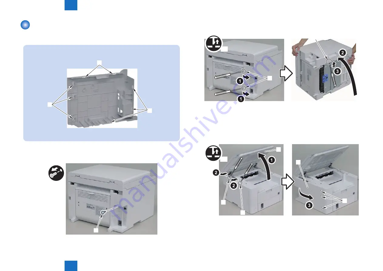
The locations of the 5 left cover claws [1] and 3 hooks [2] are shown here.
[1]
[2]
[1]
F-4-60
1) Remove the screw(black TP)[1].
[1]
F-4-61
2) Remove the 2 rear claws [1]
3)Place the machine with its right side down, and remove the claw[2] on the underside.
[2]
x3
[1]
4)Return the host machine to its original position.
5)Open the reader unit[1] and remove the 2 upper claws[2].
6)Remove the left cover[3]
• 3 hooks[4]
x2
[2]
[2]
[1]
[4]
[3]
F-4-62
F-4-63
Summary of Contents for FAXPHONE L190
Page 470: ...5 5 Adjustment Adjustment Mechanical Adjustment ...
Page 480: ...7 7 Error Codes Error Codes Overview Error Codes ...
Page 484: ...8 8 Service Mode Service Mode Overview COPIER FEEDER FAX TESTMODE ...
Page 501: ... Service Tools Solvent Oil List General Circuit Diagram General Timing Chart Appendix ...


