4
4
4-249
4-249
Disassembly/Assembly > Controller System > Removing the Drive Belt (L418S/L410/L190) > Procedure
Disassembly/Assembly > Controller System > Removing the Drive Belt (L418S/L410/L190) > Procedure
Caution:
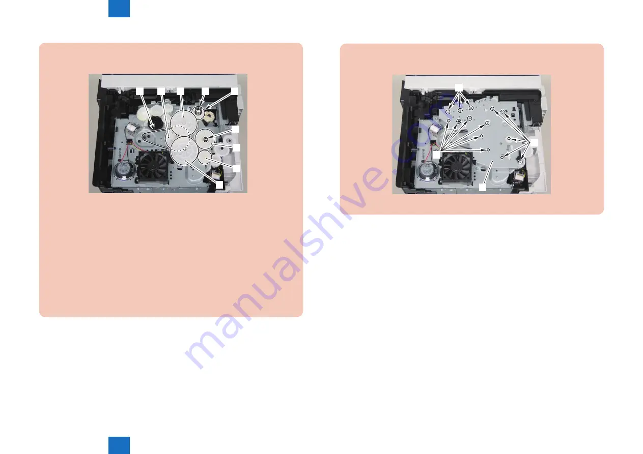
Assemble the drive gear in the order shown in the below picture.
[1]
[2]
[3]
[4]
[5]
[6]
[7]
[8]
[9]
[1] Primary deceleration pulley [6] Gear coupling
[2] Timing belt [7] Feed deceleration gear
[3] Fixing ratchet gear [8] Compression spring
[4] Fixing transmission gear [9] Compression spring
[5] Cartridge transmission gear
[6] Gear coupling
[7] Feed deceleration gear
[8] Compression spring
[9] Compression spring
F-4-664
Caution:
Align the drive cover [2] with the 14 shaft holes [1] to mount it.
[2]
[1]
[1]
[1]
F-4-665
Summary of Contents for FAXPHONE L190
Page 470: ...5 5 Adjustment Adjustment Mechanical Adjustment ...
Page 480: ...7 7 Error Codes Error Codes Overview Error Codes ...
Page 484: ...8 8 Service Mode Service Mode Overview COPIER FEEDER FAX TESTMODE ...
Page 501: ... Service Tools Solvent Oil List General Circuit Diagram General Timing Chart Appendix ...


