Chapter 12
12-10
12.3 Service Soft Switch Settings (SSSW)
12.3.1 Outline
12.3.1.1 Explanation of SOFT SWITCH
0018-5013
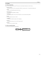
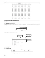
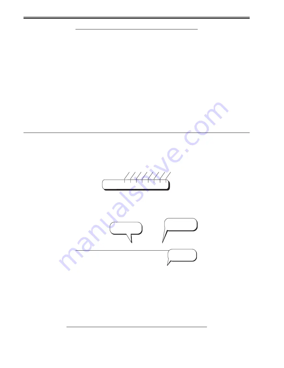
The items registered and set by each of these switches comprise 8-bit switches. The figure below shows which numbers are assigned to which bits. Each bit has a
value of either 0 or 1.
F-12-5
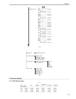
Below are examples showing how to read bit switch tables.
F-12-6
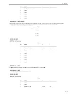
12.3.2 SSSW-SW02:
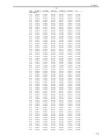
12.3.2.1 List of Functions
0018-5014
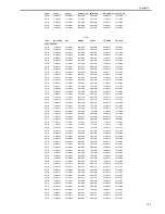
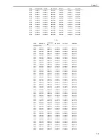
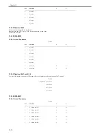
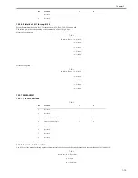
T-12-7
SW47
00000000
00000000
00000000
00000000
00000000
SW48
00100101
00100101
00100101
00100101
00100101
SW49
10001000
10001000
10001000
10001000
10001000
SW50
00000000
00000000
00000000
00000000
00000000
SW51
00000000
00000000
00000000
00000000
00000000
SW52
10000011
10000011
10000011
10000011
10000011
SW53
10000011
10000011
10000011
10000011
10000011
SW54
00000011
00000011
00000001
00000101
00000011
SW55
00000000
00000000
00000000
00000000
00000000
SW56
00000000
00000000
00000000
00000000
00000000
SW57
00000000
00000000
00000000
00000000
00000000
SW58
00000000
00000000
00000000
00000000
00000000
SW59
00000000
00000000
00000000
00000000
00000000
SW60
00000000
00000000
00000000
00000000
00000000
SW61
11110000
11110000
11110000
11110000
11110000
SW62
00000000
00000000
00000000
00000000
00000000
SW63
00000000
00000000
00000000
00000000
00000000
SW64
00000000
00000000
00000000
00000000
00000000
Bit
Function
1
0
1
Not used
-
-
2
RTN signal transmission condition
1
0*
TYPE
EUROPE2
LUXEMBOU
RG
GREECE
TAIWAN
OTHERS
SW01
0
0
0
0
0
0
0
0
Bit 1 Bit 2 Bit 3 Bit 4 Bit 5 Bit 6 Bit 7 Bit 8
Not used
Not used
Not used
Document scan width
Not used
Not used
Not used
Not used
-
-
-
LETTER
-
-
-
-
Function
1
2
3
4
5
6
7
8
Bit
1
0
Indicates that the
setting is "1".
Indicates the
default settings.
Indicates that the
setting is "0".
-
-
-
A4*
-
-
-
-
Summary of Contents for FaxPhone L90
Page 1: ...Feb 6 2008 Service Manual L90 L140 L160 L230 Series FAX L140 ...
Page 2: ......
Page 6: ......
Page 12: ...Contents ...
Page 13: ...Chapter 1 Introduction ...
Page 14: ......
Page 16: ......
Page 23: ...Chapter 2 Document Feed and Exposure System ...
Page 24: ......
Page 26: ......
Page 33: ...Chapter 3 Laser Exposure ...
Page 34: ......
Page 36: ......
Page 38: ......
Page 39: ...Chapter 4 Image Formation ...
Page 40: ......
Page 42: ......
Page 44: ......
Page 45: ...Chapter 5 Pickup and Feed System ...
Page 46: ......
Page 48: ......
Page 53: ...Chapter 6 Fixing System ...
Page 54: ......
Page 56: ......
Page 61: ...Chapter 7 External and Controls ...
Page 62: ......
Page 72: ......
Page 73: ...Chapter 8 Maintenance and Inspection ...
Page 74: ......
Page 76: ......
Page 80: ......
Page 81: ...Chapter 9 Measurement and Adjustments ...
Page 82: ......
Page 84: ......
Page 87: ...Chapter 10 Correcting Faulty Images ...
Page 88: ......
Page 90: ......
Page 93: ...Chapter 11 Error Code ...
Page 94: ......
Page 95: ...Contents Contents 11 1 Error Code 11 1 11 1 1 Error Code 11 1 ...
Page 96: ......
Page 100: ......
Page 101: ...Chapter 12 Service Mode ...
Page 102: ......
Page 104: ......
Page 121: ...Chapter 13 Service Tools ...
Page 122: ......
Page 123: ...Contents Contents 13 1 Service Tools 13 1 13 1 1 Solvent Oil List 13 1 ...
Page 124: ......
Page 126: ......
Page 127: ...Feb 6 2008 ...
Page 128: ......


