background image

Contents

Contents

3.1 Overview/Configuration ................................................................................................................................................3-1

3.1.1 Overview...................................................................................................................................................................................... 3-1

3.2 Parts Replacement Procedure.........................................................................................................................................3-1

3.2.1 Laser/Scanner Unit....................................................................................................................................................................... 3-1

3.2.1.1 Preparation for Removing the Laser/Scanner Unit .........................................................................................................................................3-1

3.2.1.2 Removing the Laser/Scanner Unit ..................................................................................................................................................................3-1

Summary of Contents for FaxPhone L90

Page 1: ...Feb 6 2008 Service Manual L90 L140 L160 L230 Series FAX L140 ...

Page 2: ......

Page 3: ... need arises In the event of major changes in the contents of this manual over a long or short period Canon will issue a new edition of this manual The following paragraph does not apply to any countries where such provisions are inconsistent with local law Trademarks The product names and company names used in this manual are the registered trademarks of the individual companies Copyright This ma...

Page 4: ...quiring care to avoid combustion fire Indicates an item prohibiting disassembly to avoid electric shocks or problems Indicates an item requiring disconnection of the power plug from the electric outlet Indicates an item intended to provide notes assisting the understanding of the topic in question Indicates an item of reference assisting the understanding of the topic in question Provides a descri...

Page 5: ...sed to indicate Low The voltage value how ever differs from circuit to circuit In addition the asterisk as in DRMD indicates that the DRMD signal goes on when 0 In practically all cases the internal mechanisms of a microprocessor cannot be checked in the field Therefore the operations of the microprocessors used in the machines are not discussed they are explained in terms of from sensors to the i...

Page 6: ......

Page 7: ...act Sensor 2 2 2 2 2 1 Preparation for Removing the Contact Sensor 2 2 2 2 2 2 Removing the Contact Sensor 2 2 2 2 3 Separation Roller 2 3 2 2 3 1 Preparation for Removing the Document Separation Roller 2 3 2 2 3 2 Removing the Document Separation Roller 2 3 2 2 4 Feed Roller 2 4 2 2 4 1 Preparation for Removing the Document Feed Roller 2 4 2 2 4 2 Removing the Document Feed Roller 2 4 2 2 5 Reade...

Page 8: ...up Unit 5 2 5 3 1 2 Removing the Paper Pickup Unit 5 2 5 3 2 Cassette Pickup Roller 5 3 5 3 2 1 Removing the Cassette Pickup Roller 5 3 5 3 3 Cassette Pickup Solenoid 5 3 5 3 3 1 Preparation for Removing the Cassette Pickup Solenoid 5 3 5 3 3 2 Removing the Cassette Pickup Solenoid 5 3 5 3 4 Cassette Separation Pad 5 3 5 3 4 1 Removing the Cassette Separation Pad 5 3 5 3 5 Main Motor 5 4 5 3 5 1 P...

Page 9: ...Preparation for Detaching the Cartridge Cover 7 3 7 2 7 2 Detaching the Cartridge Cover 7 3 7 2 8 Operation Panel Unit 7 4 7 2 8 1 Preparation for Removing the Control Panel Unit 7 4 7 2 8 2 Removing the Control Panel Unit 7 4 7 2 9 SCNT Board 7 4 7 2 9 1 Preparation for Removing the SCNT Board 7 4 7 2 9 2 Removing the SCNT Board 7 4 7 2 10 DCNT Board 7 4 7 2 10 1 Preparation for Removing the DCNT...

Page 10: ...in 9 1 9 1 2 Read Adjustment 9 1 9 1 3 Print Adjustment 9 1 Chapter 10 Correcting Faulty Images 10 1 Troubleshooting 10 1 10 1 1 Phenomenon Table 10 1 10 1 1 1 Symptoms 10 1 10 2 Outline of Electrical Components 10 1 10 2 1 Sensor 10 1 10 2 1 1 Arrangement of Sensors and Switches 10 1 10 2 2 PCBs 10 2 10 2 2 1 Arrangement of PCBs 10 2 Chapter 11 Error Code 11 1 Error Code 11 1 11 1 1 Error Code 11...

Page 11: ...2 3 7 SSSW SW51 12 13 12 3 7 1 List of Functions 12 13 12 3 7 2 Details of Bit 3 and Bit 4 12 13 12 3 8 SSSW SW54 12 14 12 3 8 1 List of Functions 12 14 12 3 8 2 Details of Bit 6 and Bit 7 12 14 12 3 8 3 Details of Bit 8 12 14 12 4 Report Output REPORT 12 15 12 4 1 SERVICE DATA LIST 12 15 12 5 Test Mode TEST 12 15 12 5 1 Overview 12 15 12 5 1 1 Test Mode Overview 12 15 12 5 1 2 Test Mode Menu 12 1...

Page 12: ...Contents ...

Page 13: ...Chapter 1 Introduction ...

Page 14: ......

Page 15: ...y of Laser Light 1 2 1 1 2 2 Handling the Laser Unit 1 3 1 1 2 3 Safety of Toner 1 3 1 1 2 4 Point to Note about Fire 1 3 1 1 2 5 Point to Note about Battery Replacement 1 3 1 1 3 Function List 1 4 1 1 3 1 Scanning Range Transmission 1 4 1 1 3 2 Printing Range Reception 1 4 1 1 3 3 Printing Range Printer 1 5 1 1 3 4 System Requirements for Printer Driver 1 5 ...

Page 16: ......

Page 17: ...ery tray H Automatic document feeder ADF B Paper delivery tray extension I Document feeder tray C Cartridge cover J Document feeder tray extention D Notch K Document delivery tray E Operation panel L Document delivery tray extension F Document release lever M Paper stack cover G Document guides A B I J C D E F G M K L H P N O U T R S Q ...

Page 18: ...ation of the product by the user N Handset Optional R External device jack O Handset cradle Optional S Line jack P USB port T Handset cable retainer Optional Q Handset jack U Power socket A One touch speed dialing button K Hook button B LCD L Numeric buttons C Additional mode button M Tone button D Menu button N Copy button E Status button O button F Image Quality button P Density button G Directo...

Page 19: ...th toner wash with water at once 2 Do not use warm or hot water which will cause the toner to jell permanently fusing it with the fibers of the clothes 3 Do not bring toner into contact with vinyl material They are likely to react with each other 1 1 2 4 Point to Note about Fire 0018 4896 It is dangerous to throw lithium batteries and parts and components containing flammable substances such as ca...

Page 20: ... width 8 Scanning drop out range 4 Right margin 9 Scanning range 5 Top margin 10 Document trailing edge Item A4 Letter Legal Effective scanning width 208 1 0 1 0 mm 214 1 0 1 0 mm 214 1 0 1 0 mm Left margin 1 0 2 0 2 0 mm 1 0 2 0 2 0 mm 1 0 2 0 2 0 mm Right margin 1 0 mm 1 0 mm 1 0 mm Top margin ADF 2 0 2 0 2 0 mm 2 0 2 0 2 0 mm 2 0 2 0 2 0 mm Bottom margin ADF 2 0 2 0 2 0 mm 2 0 2 0 2 0 mm 2 0 2 ...

Page 21: ... length 290 3 0 3 0 mm 272 4 3 0 3 0 mm 348 6 3 0 3 0 mm Left margin 2 0 2 0 2 0 mm 2 0 2 0 2 0 mm 2 0 2 0 2 0 mm Right margin 2 0 mm 2 0 mm 2 0 mm Top margin 2 0 2 0 2 0 mm 2 0 2 0 2 0 mm 2 0 2 0 2 0 mm Bottom margin 5 0 7 0 4 0 mm 5 0 7 0 4 0 mm 5 0 7 0 4 0 mm 1 Paper leading edge 6 Effective printing length 2 Left margin 7 Bottom margin 3 Effective printing width 8 Printing drop out range 4 Rig...

Page 22: ...MB of RAM or greater is recommended At least 355MB or greater is recommended Windows Me Intel Pentium 150 MHz or greater 32 MB of RAM or greater is recommended At least 295MB or greater is recommended Windows 2000 Professional Intel Pentium 133 MHz or greater 64 MB of RAM or greater is recommended At least 655MB or greater is recommended Windows XP Pentium Celeron series 300 MHz or greater 128 MB ...

Page 23: ...Chapter 2 Document Feed and Exposure System ...

Page 24: ......

Page 25: ... Removing the Document Separation Roller 2 3 2 2 3 2 Removing the Document Separation Roller 2 3 2 2 4 Feed Roller 2 4 2 2 4 1 Preparation for Removing the Document Feed Roller 2 4 2 2 4 2 Removing the Document Feed Roller 2 4 2 2 5 Reader Unit 2 5 2 2 5 1 Preparation for Removing the Reader Unit 2 5 2 2 5 2 Removing the Reader Unit 2 5 2 2 6 Document Feed Motor 2 5 2 2 6 1 Preparation for Removin...

Page 26: ......

Page 27: ... Removing the Document Feed Tray and the Paper Tray Cover 2 Detach the right cover page 7 2 Reference Detaching the Right Cov er 3 Detach the left cover page 7 2 Reference Detaching the Left Cover 4 Detach the front cover page 7 1 Reference Detaching the Front Cov er 5 Detach the rear cover page 7 1 Reference Detaching the Rear Cover 6 Detach the cartridge cover page 7 3 Reference Detaching the Ca...

Page 28: ...he rear cover page 7 1 Reference Detaching the Rear Cover 6 Detach the cartridge cover page 7 3 Reference Detaching the Car tridge Cover 7 Remove the control panel unit page 7 4 Rference Removing the Con trol Panel Unit 8 Detach the upper cover page 7 3 Reference Detaching the Upper Cov er 9 Remove the reader unit page 2 5 Reference Removing the Reader Unit 2 2 2 2 Removing the Contact Sensor 0018...

Page 29: ...ce Detaching the Front Cov er 5 Detach the rear cover page 7 1 Reference Detaching the Rear Cover 6 Detach the cartridge cover page 7 3 Reference Detaching the Car tridge Cover 7 Remove the control panel unit page 7 4 Rference Removing the Con trol Panel Unit 8 Detach the upper cover page 7 3 Reference Detaching the Upper Cov er 9 Remove the reader unit page 2 5 Reference Removing the Reader Unit ...

Page 30: ... front cover page 7 1 Reference Detaching the Front Cov er 5 Detach the rear cover page 7 1 Reference Detaching the Rear Cover 6 Detach the cartridge cover page 7 3 Reference Detaching the Car tridge Cover 7 Remove the control panel unit page 7 4 Rference Removing the Con trol Panel Unit 8 Detach the upper cover page 7 3 Reference Detaching the Upper Cov er 9 Remove the reader unit page 2 5 Refere...

Page 31: ... Cov er 2 2 5 2 Removing the Reader Unit 0018 3975 1 Remove the clamp 1 2 Disconnect the 4 connectors 2 3 Remove the screw 3 4 Free the harness 5 from the clamp 4 5 Remove the 3 screws 6 to remove the reader unit 7 F 2 18 2 2 6 Document Feed Motor 2 2 6 1 Preparation for Removing the Document Feed Motor 0018 4175 1 Remove the document feed tray and the paper tray cover page 7 2 Ref erence Removing...

Page 32: ...ar Cover 6 Detach the cartridge cover page 7 3 Reference Detaching the Car tridge Cover 7 Remove the control panel unit page 7 4 Rference Removing the Con trol Panel Unit 8 Detach the upper cover page 7 3 Reference Detaching the Upper Cov er 9 Remove the reader unit page 2 5 Reference Removing the Reader Unit 2 2 7 2 Removing the DS DES Sensor 0018 4178 1 Free the claw 1 and detach the upper reade...

Page 33: ...Chapter 3 Laser Exposure ...

Page 34: ......

Page 35: ... 3 1 Overview Configuration 3 1 3 1 1 Overview 3 1 3 2 Parts Replacement Procedure 3 1 3 2 1 Laser Scanner Unit 3 1 3 2 1 1 Preparation for Removing the Laser Scanner Unit 3 1 3 2 1 2 Removing the Laser Scanner Unit 3 1 ...

Page 36: ......

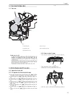
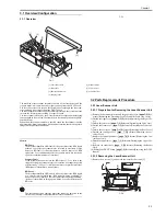
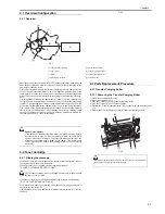
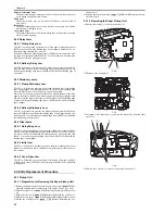
Page 37: ...dentifies a scanner fault BD Error The machine identifies a BD error if it does not detect the BDI signal at a specific interval while the BDI signal is being generated It however does not identify a BD error under the following condition the door is identified as being open within 0 2 sec after detection of a BD error The laser scanner unit contains parts that cannot be adjusted in the field Do n...

Page 38: ......

Page 39: ...Chapter 4 Image Formation ...

Page 40: ......

Page 41: ...1 Overview Configuration 4 1 4 1 1 Overview 4 1 4 2 Toner Cartridge 4 1 4 2 1 Display the message 4 1 4 3 Parts Replacement Procedure 4 1 4 3 1 Transfer Charging Roller 4 1 4 3 1 1 Removing the Transfer Charging Roller 4 1 ...

Page 42: ......

Page 43: ... against light the machine is equipped with a drum cover shutter The drum cover shutter must never be opened unless doing so proves to be absolutely necessary 4 2 Toner Cartridge 4 2 1 Display the message 0018 5781 If the toner level comes near approx 100 sheets standard original the fol lowing message is shown on the display When the toner cover is opend the message will disappear TONER LOW PREPA...

Page 44: ......

Page 45: ...Chapter 5 Pickup and Feed System ...

Page 46: ......

Page 47: ... 3 Cover Open Jam 5 2 5 3 Parts Replacement Procedure 5 2 5 3 1 Pickup Unit 5 2 5 3 1 1 Preparation for Removing the Paper Pickup Unit 5 2 5 3 1 2 Removing the Paper Pickup Unit 5 2 5 3 2 Cassette Pickup Roller 5 3 5 3 2 1 Removing the Cassette Pickup Roller 5 3 5 3 3 Cassette Pickup Solenoid 5 3 5 3 3 1 Preparation for Removing the Cassette Pickup Solenoid 5 3 5 3 3 2 Removing the Cassette Pickup...

Page 48: ......

Page 49: ...sensitive drum making sure that the leading edge of the image and the leading edge of the print paper will match 6 The print paper is then moved to the face down tray for delivery by the work of the pressure roller and the face down delivery roller When the initial rotation ready state The machine is in an initial rotation ready state when the main motor is on and in addition the fixing assembly t...

Page 50: ... 2 Delivery Stationary Jam 0018 4907 The CPU will assume the presence of a delivery stationary jam if the delivery sensor PS803 does snot detect the leading edge of print paper during a pe riod of about 2 0 sec after the paper leading edge sensor PS801 has detected the trailing edge of print paper 5 2 4 Other Jams 5 2 4 1 Fixing Wrap Jam 0018 4908 The CPU will assume that paper has wrap jam if the...

Page 51: ...cover page 7 2 Reference Detaching the Left Cover 4 Detach the rear cover page 7 1 Reference Detaching the Rear Cover 5 3 3 2 Removing the Cassette Pickup Solenoid 0018 4189 1 Remove the 2 flat cables 1 2 Disconnect the 8 connectors 2 3 Remove the 6 screws 3 and detach the SCNT board 4 4 Free the harness 6 from the clamp 5 5 Remove the screw 7 and detach the Speaker 8 F 5 7 6 Remove the 4 screws 1...

Page 52: ... er 5 Detach the rear cover page 7 1 Reference Detaching the Rear Cover 6 Detach the cartridge cover page 7 3 Reference Detaching the Car tridge Cover 7 Remove the control panel unit page 7 4 Rference Removing the Con trol Panel Unit 8 Detach the upper cover page 7 3 Reference Detaching the Upper Cov er 9 Remove the reader unit page 2 5 Reference Removing the Reader Unit 10 Remove the DCNT board p...

Page 53: ...Chapter 6 Fixing System ...

Page 54: ......

Page 55: ... 6 3 6 3 2 Detection of a Fault 6 3 6 4 Parts Replacement Procedure 6 3 6 4 1 Fixing Unit 6 3 6 4 1 1 Preparation for Removing the Fixing Unit 6 3 6 4 1 2 Removing the Fixing Unit 6 3 6 4 2 Fixing Film Unit 6 3 6 4 2 1 Preparation for Removing the Fixing Film Unit 6 3 6 4 2 2 Removing the Fixing Film Unit 6 3 6 4 3 Fixing Pressure Roller 6 4 6 4 3 1 Preparation for Removing the Fixing Pressure Rol...

Page 56: ......

Page 57: ...he print paper before it moves out of the fixing assembly Once outside the fixing assembly the print paper is delivered to the delivery tray by the work of the face down delivery roller upon detection by the delivery sensor PS803 6 2 Various Control Mechanisms 6 2 1 Controlling the Temperature of the Fixing Unit 6 2 1 1 Heater Temperature Control 0018 4914 The heater temperature control mechanism ...

Page 58: ...the temperature of the fixing heater is lower than the target temperature thus preventing overheating of the fixing film 4 down sequence during continuous printing so as to prevent overheating of the edges of the heater In this control the CPU of the DCNT board checks the length and width of paper if the size of the paper matches a specific set of conditions the machine is shifted to long narrow m...

Page 59: ...control 2 It monitors the temperature of the thermistor every 5 msec if the temper ature of the thermistor is 230 deg C or more 30 times continuously 3 It monitors the temperature of the thermistor every 5 msec if the temper ature is 100 deg C or less at time of normal temperature control or 55 deg C or less at time of cleaning mode 240 times continuously 4 After the temperature of the thermistor ...

Page 60: ...ng the Right Cov er 3 Detach the left cover page 7 2 Reference Detaching the Left Cover 4 Detach the front cover page 7 1 Reference Detaching the Front Cov er 5 Detach the rear cover page 7 1 Reference Detaching the Rear Cover 6 Detach the cartridge cover page 7 3 Reference Detaching the Car tridge Cover 7 Remove the control panel unit page 7 4 Rference Removing the Con trol Panel Unit 8 Remove th...

Page 61: ...Chapter 7 External and Controls ...

Page 62: ......

Page 63: ... Preparation for Removing the Control Panel Unit 7 4 7 2 8 2 Removing the Control Panel Unit 7 4 7 2 9 SCNT Board 7 4 7 2 9 1 Preparation for Removing the SCNT Board 7 4 7 2 9 2 Removing the SCNT Board 7 4 7 2 10 DCNT Board 7 4 7 2 10 1 Preparation for Removing the DCNT Board 7 4 7 2 10 2 Removing the DCNT Board 7 4 7 2 11 High voitage Power Supply PCB 7 5 7 2 11 1 Preparation for Removing the Hig...

Page 64: ...Contents 7 2 17 Speaker 7 7 7 2 17 1 Preparation for Removing the Speaker 7 7 7 2 17 2 Removing the Speaker 7 7 ...

Page 65: ...2 1 1 Preparation for Detaching the Front Cover 0018 3823 1 Remove the document feed tray and the paper tray cover page 7 2 Ref erence Removing the Document Feed Tray and the Paper Tray Cover 2 Detach the right cover page 7 2 Reference Detaching the Right Cov er 3 Detach the left cover page 7 2 Reference Detaching the Left Cover 7 2 1 2 Detaching the Front Cover 0018 3809 1 Disengage the 2 claws 1...

Page 66: ... right cover 4 in the direction of the arrow B 4 Disengage the claw 5 to detach the right cover 4 F 7 5 7 2 4 Left Cover 7 2 4 1 Preparation for Detaching the Left Cover 0018 3821 1 Remove the document feed tray and the paper tray cover page 7 2 Ref erence Removing the Document Feed Tray and the Paper Tray Cover 7 2 4 2 Detaching the Left Cover 0018 3822 1 Open the cartridge cover 1 in the directi...

Page 67: ...ference Removing the Con trol Panel Unit 7 2 6 2 Detaching the Upper Cover 0018 3962 1 Remove the screw 1 2 Disengage the claw 2 to the direction of the arrow A to detach the up per cover to the direction of the arrow B F 7 8 7 2 7 Cartridge Cover 7 2 7 1 Preparation for Detaching the Cartridge Cover 0018 3955 1 Remove the document feed tray and the paper tray cover page 7 2 Ref erence Removing th...

Page 68: ... Removing the SCNT Board 0018 3969 1 Remove the flat cable 1 and disconnect the 7 connectors 2 2 Remove the 6 screws 3 and detach the SCNT board 4 F 7 11 7 2 10 DCNT Board 7 2 10 1 Preparation for Removing the DCNT Board 0018 3973 1 Remove the document feed tray and the paper tray cover page 7 2 Ref erence Removing the Document Feed Tray and the Paper Tray Cover 2 Detach the right cover page 7 2 R...

Page 69: ...d Tray and the Paper Tray Cover 2 Detach the right cover page 7 2 Reference Detaching the Right Cov er 3 Detach the left cover page 7 2 Reference Detaching the Left Cover 4 Detach the rear cover page 7 1 Reference Detaching the Rear Cover 5 Detach the cartridge cover page 7 3 Reference Detaching the Car tridge Cover 7 2 11 2 Removing the High Voltage Power Supply Board 0018 4154 1 Disconnect the f...

Page 70: ...tors 1 and free the harness 3 froma hte harness guide 2 2 Free the 2 claws 4 and detach the paper leading edge paper width sensor PCB 5 F 7 19 7 2 14 Paper Delivery Sensor 7 2 14 1 Preparation for Removing the Paper Delivery Sensor PCB 0018 4157 1 Remove the document feed tray and the paper tray cover page 7 2 Ref erence Removing the Document Feed Tray and the Paper Tray Cover 2 Detach the right c...

Page 71: ...e rear cover page 7 1 Reference Detaching the Rear Cover 5 Detach the cartridge cover page 7 3 Reference Detaching the Car tridge Cover 7 2 16 2 Removing the Paper Width Sensor PCB 0018 4164 1 Disconnect the 6 connectors 1 and free the harness 3 from the harness guide 2 2 Free the 2 claws 4 and detach the paper width sensor PCB 5 F 7 25 7 2 17 Speaker 7 2 17 1 Preparation for Removing the Speaker ...

Page 72: ......

Page 73: ...Chapter 8 Maintenance and Inspection ...

Page 74: ......

Page 75: ...nt Parts 8 1 8 2 Consumables 8 1 8 2 1 Consumable 8 1 8 3 Periodical Service 8 1 8 3 1 Scheduled service Parts 8 1 8 4 Cleaning 8 1 8 4 1 Items Requiring Cleaning 8 1 8 4 2 Cleaning Method external covers 8 2 8 4 3 Cleaning Method scanning unit 8 2 8 4 4 Cleaning printer unit 8 3 ...

Page 76: ......

Page 77: ...ear in copied or transmitted images White sheet When image scanned from the ADF becomes lighter Service technician Document pickup roller When document pickup performance has lowered Document separation roller When document separation and or feed performance has lowered Separation guide When document separation performance has lowered Document feed roller When document feed performance has lowered...

Page 78: ...n the Upper reader unit frame and wipe off the dirt with a soft dry cloth 2 Document separation roller Open the Upper cover and wipe off the dirt with a soft dry cloth 3 Separation guide Open the Upper reader unit frame and wipe off the dirt with a soft dry cloth 4 White sheet Open the Lower reader unit frame and wipe off the dirt with a soft dry cloth 5 Document delivery roller Open the Lower rea...

Page 79: ...y wiping with lint free paper Never use water or solvent 2 Fixing Entrance Guide Dry wipe with lint free paper 3 Static Eliminator Clean with a brush 4 Pickup Roller Dry wipe with lint free paper 5 Separation Pad Dry wipe the rubber portion with lint free paper 6 Feed Roller Dry wipe with lint free paper Do not touch the sponge portion of the transfer charging roller Otherwise the back of paper ma...

Page 80: ......

Page 81: ...Chapter 9 Measurement and Adjustments ...

Page 82: ......

Page 83: ...Contents Contents 9 1 Image Adjustments 9 1 9 1 1 Adjusting the Paper Margin 9 1 9 1 2 Read Adjustment 9 1 9 1 3 Print Adjustment 9 1 ...

Page 84: ......

Page 85: ...e read start position when the ADF is used T 9 3 9 1 3 Print Adjustment 0018 5002 Press the Menu button and then the button to select ADJUST then click the OK button Useing the cursor select the item to adjust PRN MAIN REGIST Use it to adjust the print start position in main scanning direction when a printer function is in use 1 Leading edge erase 2mm 0 5 2 Trailing edge erase 2mm 0 5 3 Vertical e...

Page 86: ...mm 98 2 1 0 mm 99 1 0 5 mm 100 0 101 1 0 5 mm 102 2 1 0 mm 103 3 1 5 mm 104 4 2 0 mm 105 5 2 5 mm 106 6 3 0 mm 107 7 3 5 mm 108 8 4 0 mm 109 9 4 5 mm 110 10 5 0 mm MAIN Regist SUB Regist Setting value Contents 90 10 5 0 mm 91 9 4 5 mm 92 8 4 0 mm 93 7 3 5 mm 94 6 3 0 mm 95 5 2 5 mm 96 4 2 0 mm 97 3 1 5 mm 98 2 1 0 mm 99 1 0 5 mm 100 0 101 1 0 5 mm 102 2 1 0 mm 103 3 1 5 mm 104 4 2 0 mm 105 5 2 5 m...

Page 87: ...Chapter 10 Correcting Faulty Images ...

Page 88: ......

Page 89: ...leshooting 10 1 10 1 1 Phenomenon Table 10 1 10 1 1 1 Symptoms 10 1 10 2 Outline of Electrical Components 10 1 10 2 1 Sensor 10 1 10 2 1 1 Arrangement of Sensors and Switches 10 1 10 2 2 PCBs 10 2 10 2 2 1 Arrangement of PCBs 10 2 ...

Page 90: ......

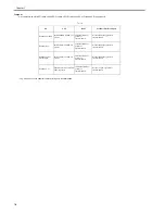
Page 91: ...sensor PS803 Paper delivery sensor PS804 Paper width sensor Level 1 Symptom Image Faults Image Faults Occurring at Specific Intervals Initial Offset in a Low Temperature Humidity Environment Black Lines Caused by Drum Memory Malfunction The Session No of Activiry report is reset each time the power is turned off and then back on Transmission Fax Related In response to a copy job while reception is...

Page 92: ...Chapter 10 10 2 10 2 2 PCBs 10 2 2 1 Arrangement of PCBs 0018 4210 F 10 2 1 High Voltage Power Supply Board 2 Power Supply Board 3 DCNT Board 4 SCNT Board 1 2 3 4 ...

Page 93: ...Chapter 11 Error Code ...

Page 94: ......

Page 95: ...Contents Contents 11 1 Error Code 11 1 11 1 1 Error Code 11 1 ...

Page 96: ......

Page 97: ... 0012 Remote side Password not match in Polling Rx 0013 The procedure signal cannot be received for 6 sec while in wait 0014 Cannot receive signal after sending FTT signal 0016 DCN was received through a non normal procedure 0017 Can t receive any response from remote side after sending type of PPS EOR EOM signal 0018 Cannot detect energy within 6 sec after sending FTT command 0019 Received DCN si...

Page 98: ...nal in phase D within 60 seconds even through energy still on the line 0065 Can t detect any control channel signal within 60 seconds after detect silence in phase D 0066 Cannot receive signal or carrier after sending CFR in V 34 0069 Capability no match paper size after received is DCS signal 0070 Reception was manually canceled on the machine 0071 The machine s memory is full 0080 The recipient ...

Page 99: ...onds 00D9 Can t detect correct phase 3 signal after detect silence after phase 2 00DA Can t detect phase 4 signal within 30 seconds or remote side hang up over 6 seconds 00DB Can t received any T30 signal within 15 seconds within phase 4 00DC Received T30 signal in phase 4 other than DCS DIS or DTC 00DE Remote side no SUB capability in V34 00E0 At phase D transmitting units out PPS_NULL 3 times co...

Page 100: ......

Page 101: ...Chapter 12 Service Mode ...

Page 102: ......

Page 103: ...unctions 12 11 12 3 4 2 Details of Bit 3 12 12 12 3 5 SSSW SW30 12 12 12 3 5 1 List of Functions 12 12 12 3 5 2 Details of Bit 7 and Bit 8 12 12 12 3 6 SSSW SW37 12 12 12 3 6 1 List of Functions 12 12 12 3 6 2 Details of Bit 1 through Bit 6 12 13 12 3 7 SSSW SW51 12 13 12 3 7 1 List of Functions 12 13 12 3 7 2 Details of Bit 3 and Bit 4 12 13 12 3 8 SSSW SW54 12 14 12 3 8 1 List of Functions 12 14...

Page 104: ......

Page 105: ...VERSION DISPLAY Use it to indicate version information on the display SOFT SWITCH Use it to make settings that relate to basic fax service functions as for correcting communication problems REPORT Use it to output reports on various service data CLEAR DATA Various data are initialized by selecting one of these setting items FUNCTION Use it to print out a print pattern or to test the ADF for paper ...

Page 106: ...F HIGH FREQ LEVEL DTMF LOW FREQ LEVEL CNG LEVEL CED LEVEL ECM MODE CODING SCHEME 2mm 0 to 5 2mm 0 to 5 2mm 0 to 5 33600 bps 33600 to 2400 33600 bps 33600 to 2400 10dBm 4 to 15 5dBm 8dBm 10dBm 10dBm ON OFF MMR MR MH Not used Not used Not used Not used EC UK SWEDEN SWITZERLAND AUSTRIA DENMARK NORWAY HOLLAND BELGIUM AUSTRALIA FINLAND N Z ITALY SPAIN PORTUGAL IRELAND HONG KONG MALAYSIA HUNGARY SAF KOR...

Page 107: ...Not used Not used Not used Not used Not used Not used Not used Not used Not used Not used Not used Not used Not used Not used Not used Not used 1 2 3 4 5 6 7 8 SW01 SW02 SW07 SW08 SW09 SW10 SW16 SW17 SW18 SW19 SW20 SW21 SW22 SW23 SW24 SW30 SW37 SW46 SW51 SW52 SW53 SW54 0 0 0 1 0 0 0 1 0 0 0 1 0 0 0 0 0 1 0 0 0 0 1 0 0 0 1 1 SW55 SW64 SW03 SW06 SW11 SW15 SW25 SW29 SW31 SW36 SW38 SW45 SW47 SW50 CLEA...

Page 108: ...0000000 00000000 00000000 SW34 00000000 00000000 00000000 00000000 00000000 00000000 SW35 00000101 00000101 00000101 00000101 00000101 00000101 SW36 01010001 01010001 01010001 01010001 01010001 01010001 SW37 00000000 00000000 00000000 00000000 00000000 00000000 SW38 10000000 10000000 10000000 10000000 10000000 10000000 SW39 10000000 10000000 10000000 10000000 10000000 10000000 SW40 00000000 000000...

Page 109: ... 00010110 00010110 00010110 11000110 00010110 00010110 SW31 01010100 01010100 01010100 01000100 01010100 01011000 SW32 00000000 00000000 00000000 00000000 00000000 00000000 SW33 00000000 00000000 00000000 00000000 00000000 00000000 SW34 00000000 00000000 00000000 00000000 00000000 00000000 SW35 00000101 00000101 00000101 00000101 00000101 00000101 SW36 01010001 01010001 01010001 01010001 01010001 ...

Page 110: ...0 SW28 11101110 11101110 11100101 11100101 11100001 11100101 SW29 11110000 11110000 11110000 11110000 11110000 11110000 SW30 00010110 00010110 00010110 11000110 10011010 11000110 SW31 01010100 01010100 01010100 01010100 01010100 01010100 SW32 00000000 00000000 00000000 00000000 00000000 00000000 SW33 00000000 00000000 00000000 00000000 00000000 00000000 SW34 00000000 00000000 00000000 00000000 000...

Page 111: ... 01000000 01000000 01000000 10100000 01000000 01000000 SW25 00000000 00000000 00000000 00000000 00000000 00010000 SW26 01000100 01000100 01000100 01000100 01000100 01000100 SW27 00000000 00000000 00000000 00000000 00000000 00000000 SW28 11100101 11100101 11100101 11100101 11100001 11100101 SW29 11110000 11110000 11110000 11110000 11110000 11110000 SW30 00010110 11000110 11000110 11000110 00010110 ...

Page 112: ...010 SW20 00000110 00000111 00000110 00000110 00000110 00000110 SW21 00000100 00000100 00000100 00000100 00000100 00000100 SW22 10101000 10101000 10100000 10101000 10101000 10101000 SW23 10100010 00010010 00010010 10100010 10100010 00010010 SW24 01000000 01000000 01000000 01000000 01000000 01000000 SW25 00000000 00000000 00000000 00000000 00000000 00000000 SW26 01000100 01000100 01000100 01000100 0...

Page 113: ... SW14 01000000 01000000 01000000 01000000 01000000 SW15 10110000 10110101 10110101 10011000 10011101 SW16 00000000 00000000 00000000 00000000 00000000 SW17 00000000 00000000 00000000 00000000 00000000 SW18 01000001 01000001 01000001 01000001 01000001 SW19 00011010 01011010 01011010 11011010 01011010 SW20 00000110 00000110 00000110 00000110 00000110 SW21 00000100 00000100 00000100 00000100 00000100...

Page 114: ...00011 SW54 00000011 00000011 00000001 00000101 00000011 SW55 00000000 00000000 00000000 00000000 00000000 SW56 00000000 00000000 00000000 00000000 00000000 SW57 00000000 00000000 00000000 00000000 00000000 SW58 00000000 00000000 00000000 00000000 00000000 SW59 00000000 00000000 00000000 00000000 00000000 SW60 00000000 00000000 00000000 00000000 00000000 SW61 11110000 11110000 11110000 11110000 111...

Page 115: ...ails of Bit 1 0018 5017 If a transmission ends in error sound the alarm for 3 sec If not desired change it to Do not sound 12 3 3 3 Details of Bit 2 0018 5018 Use it to select a page timer setting for manual transmission 12 3 4 SSSW SW16 12 3 4 1 List of Functions 0018 5019 T 12 10 3 RTN signal transmission condition 1 0 4 Not used 5 Not used 6 Not used 7 Not used 8 Not used Bit2 Bit3 0 0 10 1 0 1...

Page 116: ... will be ture depending on the combination of bit 7 and bit 8 T 12 12 12 3 6 SSSW SW37 12 3 6 1 List of Functions 0018 5026 T 12 13 4 Not used 5 Not used 6 Not used 7 Not used 8 Not used Bit Function 1 0 1 Not used 2 Not used 3 Not used 4 Not used 5 Not used 6 Not used 7 Pause time 1 0 8 Pause time 1 0 Bit7 Bit8 0 0 2 0 sec 1 0 2 5 sec 0 1 3 0 sec 1 1 3 5 sec Bit Function 1 0 1 V 34 Baud rate TX 1...

Page 117: ...etails of Bit 3 and Bit 4 0018 5029 Use it to select the mode of printing a protocol monitor report the following will be true depending on the combination of bit 3 and bit 4 T 12 17 7 Not used 8 Not used Bit1 Bit2 Bit3 0 0 0 3429 1 0 0 3200 0 1 0 3000 1 1 0 2800 0 0 1 2400 Bit4 Bit5 Bit6 0 0 0 3429 1 0 0 3200 0 1 0 3000 1 1 0 2800 0 0 1 2400 Bit Function 1 0 1 Not used 2 Not used 3 Protocol monit...

Page 118: ...8 0018 5032 Use it to select the month notation for reports If 1 is selected the month will be expressed in alphabet characters e g 25 MAR 2005 If 0 is selected year month and day will all be expressed in numberals e g 25 03 2005 1 1 Not used Bit Function 1 0 1 Not used 2 Not used 3 Not used 4 Not used 5 Not used 6 Date time notation for report 1 0 7 Date time notation for report 1 0 8 Month notat...

Page 119: ...RN In this test the printer unit will be used to print various patterns For service work be sure to use the BLACK pattern and the SQUARE pattern SERVICE DATA LIST NA M E T E L DAT E 0 8 A P R 2 0 0 5 1 8 1 5 C O U N T RY C O D E U K S W 0 1 S W 1 6 S W 1 7 S W 3 2 S W 3 3 S W 4 8 S W 4 9 S W 6 4 0 0 2 0 1 0 0 0 C 0 0 0 0 5 2 0 0 0 2 1 0 0 8 E 1 2 0 2 A D 0 0 0 0 8 2 5 A 6 0 2 0 1 5 4 8 0 2 0 4 2 2...

Page 120: ...2 2 ADF FEED TEST 0018 5038 From the FUNCTION menu select ADF FEED TEST Use the test to make sure that the ADF function of the sheet reader unit operates normally 12 5 2 3 Sensor Tests 0018 5039 From the H W TEST menu select SENSOR TEST In this test you can check the status of each sensor of this fax in items 1 to 4 on the display You can also check if sensors that use actuators and microswitches ...

Page 121: ...Chapter 13 Service Tools ...

Page 122: ......

Page 123: ...Contents Contents 13 1 Service Tools 13 1 13 1 1 Solvent Oil List 13 1 ...

Page 124: ......

Page 125: ...aning plastic note rubber metal oil and toner stains Alcohol Flammable keep away from flame Purchase locally 2 Lubricant Apply to gears between shaft and bushing Special oil Special solid lubricating material Lithium soap Tool No HY9 0007 3 Lubricant Apply between pressure roller shaft and grounding plate High performance grease Carbon black Graphite Electricity grease Tool No CK 8007 ...

Page 126: ......

Page 127: ...Feb 6 2008 ...

Page 128: ......

Reviews: