COPYRIGHT © 1998 CANON INC. CANON PC400/420/430,FC200/220 REV.0 JAN.1998 PRINTED IN JAPAN (IMPRIME AU JAPON)
10-24
CHAPTER 10 TROUBLESHOOTING
IV. TROUBLESHOOTING MALFUNCTIONS
A. Troubleshooting Malfunctions
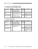
1.
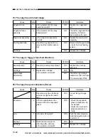
(self diagnosis; PC400/FC200)
Cause
Step
Checks
YES/NO
Remedies
1
Switch the copier ON.
Does the Jam indicator remain
On for about 0.5 sec, and does
the copier go OFF automatically
thereafter?
YES
See ‘E00’.
NO
See the discussions on
‘E2’, ‘E6’, and ‘E9’.
Cause
Step
Checks
YES/NO
Remedies
Thermistor (TH1)
1
Set the meter to the ‘12VDC’
range, and wait until the fixing
heater is sufficiently cool.
Measure the voltage between
J603-1 (+) and J603-2 (-).
Is it about 3.2 V or more?
NO
Check the wiring from the
DC controller/DC power
supply PCB to the ther-
mistor (TH1); if normal,
replace the fixing assem-
bly.
2
Does the fixing heater operate
normally?
NO
See “The fixing heater fails
to operate.”
DC controller/DC
power supply PCB
3
Switch the copier ON, and make
a copy.
Measure the voltage between
J603-1 and J603-2 once again.
Is the voltage lower than that
measured in step 1?
YES
Replace the DC controller/
DC power supply PCB.
Fixing assembly
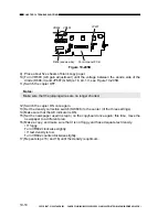
Check the wiring from the
DC controller/DC power
supply PCB to the ther-
mistor (TH1); if normal,
replace the fixing assem-
bly.
NO
2. E0

