COPYRIGHT © 1999 CANON INC. CANON CLC1120/1130/1150 REV.0 MAR. 1999 PRINTED IN JAPAN (IMPRIME AU JAPON)
vi
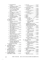
CHAPTER 3 EXPOSURE SYSTEM
I.
OPERATION................................3-1
A. Outline ....................................3-1
B. Basic Sequence of
Operations..............................3-2
1. Sequence of
Operations........................3-2
2. Scanner Home Position
Sensor and Operation ......3-3
II.
SCANNER DRIVE SYSTEM .......3-4
A. Controlling the Scanner
Motor ......................................3-4
1. Outline ..............................3-4
2. Operations........................3-5
B. Changing the Reproduction
Ratio .......................................3-5
III.
CONTROLLING THE INTENSITY
OF THE SCANNING LAMP ........3-6
A. Outline ....................................3-6
B. Operations..............................3-7
1. Turning On/Off the
Scanning Lamp ................3-7
2. Detecting the Activation
of the Scanning Lamp ......3-7
3. Detecting an Error in the
Activation of the
Scanning Lamp ................3-7
4. Controlling the Intensity
of the Scanning Lamp ......3-7
IV.
DISASSEMBLY/ASSEMBLY .......3-8
A. Original Exposure System .....3-9
1. Removing the Scanning
Lamp ................................3-9
2. Orienting the Scanning
Lamp ................................3-9
3. Removing the Standard
White Plate .................... 3-10
4. Mounting the Standard
White Plate .................... 3-10
B. Scanner Drive Assembly ..... 3-11
1. Removing the Scanner
Drive Motor.................... 3-11
2. Adjusting the Tension of the
Belt When Mounting the
Scanner Drive Motor ..... 3-11
3. Routing the Scanner
Cable ............................. 3-11
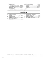
CHAPTER 4 IMAGE PROCESSING SYSTEM
I.
OUTLINE .....................................4-1
II.
CCD/CCD DRIVE........................4-2
A. Controlling the CCD ...............4-2
B. CCD Driver Circuit .................4-2
III.
ANALOG IMAGE
PROCESSING ............................4-3
IV.
DIGITAL IMAGE
PROCESSING ............................4-4
A. Outline ....................................4-4
B. Shading Correction ................4-6
a. Shading Correction ..........4-6
C. 3-Line CCD Position Matching
Circuit .....................................4-7
D. Sensor Color Correction
Circuit .....................................4-7
E. Original Position Detection
Circuit .....................................4-8
F. Black Detection Circuit and
Edge/Line Width
Detection Circuit .....................4-9
G. Chromatic Space Correction
Circuit .................................. 4-10
H. Direct Mapping Circuit ........ 4-10
I. Logarithmic Correction and
BGR-to-YMC Conversion .... 4-11
a. Logarithmic Correction .. 4-11
b. BGR-to-YMC Conversion4-11
J. Toner Color Correction
Circuit .................................. 4-12
K. Coloring/Contour
Processing .......................... 4-12
L. Density Processing ............. 4-13
M. Enlargement/Reduction,
Shift, and Edit Processing ... 4-13
N. Sharpness/Filter
Processing .......................... 4-14
O. Anti-Counterfeit
Mechanism .......................... 4-14
1. Counterfeit Tracing
Mechanism .................... 4-14
fineline6
service-repairmanual.com


