COPYRIGHT © 2001 CANON INC.
2000 2000 2000 2000
NM-PDL REV.0 JULY 2001
CHAPTER 4 DISASSEMBLY/ASSEMBLY
4-5
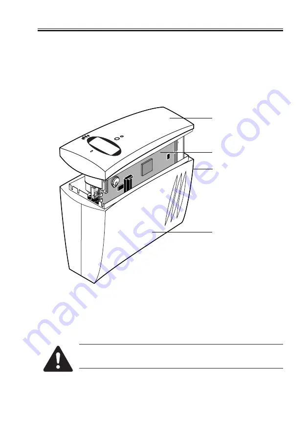
3. Place the iR-M1 face up, resting the back panel on protective foam as shown in F04-
201-02.
4. Squeeze the sides near the bottom to release the chassis cover from the front panel tabs
as shown in F04-201-02 (for tab locations, see F04-202-02 on page 4-7).
5. Grasp the front panel and pull it out of the chassis cover.
The front panel, the motherboard, and all devices are still attached to the center frame.
F04-201-02 Removing the chassis cover
6. Place the front panel face down on protective foam and set aside the chassis cover. Most
components on the center frame of the iR-M1 are now directly accessible.
Remember to attach an ESD wrist strap before handling internal parts.
Inside the chassis, the power supply is not encased. Before you service the
iR-M1, be sure to power it off as described on page 4-3 and unplug the
power cable from the back panel.
Front panel attached
to center frame
Motherboard attached
to center frame
Squeeze here and on the
opposite side
Chassis cover
Summary of Contents for FY8-13HR-000
Page 11: ...COPYRIGHT 2001 CANON INC 2000 2000 2000 2000 NM PDL REV 0 JULY 2001 CHAPTER 1 INTRODUCTION ...
Page 26: ...COPYRIGHT 2001 CANON INC 2000 2000 2000 2000 NM PDL REV 0 JULY 2001 CHAPTER 3 INSTALLATION ...
Page 81: ...COPYRIGHT 2001 CANON INC 2000 2000 2000 2000 NM PDL REV 0 JULY 2001 CHAPTER 5 TROUBLESHOOTING ...
Page 98: ...COPYRIGHT 2001 CANON INC 2000 2000 2000 2000 NM PDL REV 0 JULY 2001 CHAPTER 6 PARTS CATALOG ...
Page 102: ...COPYRIGHT 2001 CANON INC 2000 2000 2000 2000 NM PDL REV 0 JULY 2001 APPENDIX ...
Page 105: ...PRINTED IN U S A 0701AB00 This publication is printed on 100 recycled paper ...


