COPYRIGHT © 2001 CANON INC.
2000 2000 2000 2000
NM-PDL REV.0 JULY 2001
CHAPTER 4 DISASSEMBLY/ASSEMBLY
4-17
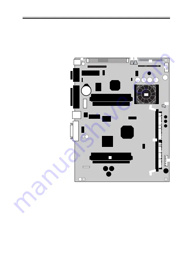
4.4 Motherboard
The iR-M1 motherboard has a 500MHz CPU and a minimum of 128MB of memory. It
processes image data, controls hard disk drive functions, controls the image data transferred
to and from the copier interface board, and handles communication between the iR-M1 and
external devices. This section includes instructions for replacing the motherboard,
motherboard battery, and DIMMs.
F04-404-01 Diagram of the iR-M1 motherboard
Key
1. RJ-45 port (J4)
2. Parallel port (J2)
3. BIOS chip
4. Battery (BT1)
5. Cpoier interface board
connector (J17)
6. Exhaust fan cable
connector (J25)
7. Exhaust fan cable
connector (J26)
8. HDD cable connector (J28)
9. UIB cable connector (J30)
10. CPU/heatsink/CPU fan
11. CPU fan cable
connector (J27)
12. DIMM socket
13. Power supply cable
connector (J29)
MS-Mounting screws (3)
Note: Components not listed
above are not used.
MS
MS
MS
[1]
[6] [7]
[8]
[9]
[10]
[11]
[12]
[13]
[4]
[5]
[2]
Summary of Contents for FY8-13HR-000
Page 11: ...COPYRIGHT 2001 CANON INC 2000 2000 2000 2000 NM PDL REV 0 JULY 2001 CHAPTER 1 INTRODUCTION ...
Page 26: ...COPYRIGHT 2001 CANON INC 2000 2000 2000 2000 NM PDL REV 0 JULY 2001 CHAPTER 3 INSTALLATION ...
Page 81: ...COPYRIGHT 2001 CANON INC 2000 2000 2000 2000 NM PDL REV 0 JULY 2001 CHAPTER 5 TROUBLESHOOTING ...
Page 98: ...COPYRIGHT 2001 CANON INC 2000 2000 2000 2000 NM PDL REV 0 JULY 2001 CHAPTER 6 PARTS CATALOG ...
Page 102: ...COPYRIGHT 2001 CANON INC 2000 2000 2000 2000 NM PDL REV 0 JULY 2001 APPENDIX ...
Page 105: ...PRINTED IN U S A 0701AB00 This publication is printed on 100 recycled paper ...


