background image

SERVICE
MANUAL

REVISION 0

FY8-13G2-000

FEB. 1999

COPYRIGHT © 1999 CANON INC.                CANON GP160 REV.0 FEB. 1999 PRINTED IN JAPAN (IMPRIME AU JAPON)

GP160F/160DF/160

Summary of Contents for GP160

Page 1: ...SERVICE MANUAL REVISION 0 FY8 13G2 000 FEB 1999 COPYRIGHT 1999 CANON INC CANON GP160 REV 0 FEB 1999 PRINTED IN JAPAN IMPRIME AU JAPON GP160F 160DF 160 ...

Page 2: ...EPARTMENT OF THE SALES COMPANY THIS DOCUMENTATION IS INTENDED FOR ALL SALES AREAS AND MAY CONTAIN INFORMA TION NOT APPLICABLE TO CERTAIN AREAS COPYRIGHT 1999 CANON INC Printed in Japan Imprimé au Japon Use of this manual should be strictly supervised to avoid disclosure of confiden tial information Prepared by OFFICE IMAGING PRODUCTS TECHNICAL SUPPORT DEPARTMENT 3 OFFICE IMAGING PRODUCTS TECHNICAL...

Page 3: ...n system s mechanical electrical system operating principles timing disassembly assembly and adjustment methods Chapter 7 Pick up Feed system Explanation of the pick up feed system s mechanical electrical system operating principles timing disassembly assembly and adjustment methods Chapter 8 Fixing system Explanation of the fixing system s mechanical electri cal system operating principles timing...

Page 4: ...D signal is 0 and ON In each chapter Power supply ON indicates the power supply SW has been turned ON the front door etc has been shut and power is being supplied to the copier 2 This unit utilizes micro processors however due to the impossibility of checking the micro processor s internal operation an explanation of the micro processor s opera tion has been omitted Furthermore assuming that inter...

Page 5: ...CU board Modular board Super G3 FAX board 8MB expanded memory Digital black and white copier and facsimile Digital black and white copier with ADF Digital black and white copier Copy board cover model Installation options Standard equipment Standard equipment Option Option Option Option Option Option Option Option Option Option Option Standard equipment Option iii GP160F GP160DF GP160 ...

Page 6: ...COPYRIGHT 1999 CANON INC CANON GP160 REV 0 FEB 1999 PRINTED IN JAPAN IMPRIME AU JAPON iv ...
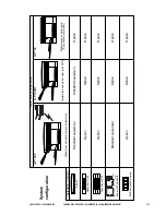
Page 7: ...TPUT 2 6 CHAPTER 3 EXPOSURE SYSTEM CHAPTER 4 IMAGE PROCESSING SYSTEM I OPERATION OVERVIEW 3 1 A Overview 3 1 B Exposure system sequence 3 2 II SCANNER DRIVE SYSTEM 3 3 A Document scanner motor 3 3 B Charging the magnification ratio 3 4 C Scanning lamp control 3 4 III DISASSEMBLY ASSEMBLY 3 5 A Scanning lamp 3 6 B Document scanning motor 3 8 I OVERVIEW 4 1 II ANALOG IMAGE PROCESSING 4 2 A Overview ...

Page 8: ...IAS CONTROL 6 8 A Operation 6 8 VII CARTRIDGE DETECTION 6 9 A Operation 6 9 I OVERVIEW 7 1 A Construction Overveiw 7 1 II PICK UP FEEDING OPERATION 7 2 A Overveiw 7 2 III CASSETTE PICK UP MECHANISM 7 3 A Pick up oparation 7 3 B Retry pick up 7 5 C Paper size detection 7 6 IV MULTI FEEDER PICK UP 7 7 A Overview 7 7 B Multi feeder pick up mechanism 7 8 C Multi feeder retry pick up 7 9 D Multi feeder...

Page 9: ... IV OPERATION OVERVIEW 10 5 A Overview 10 5 B Basic Sequence 10 6 V FEEDER MOTOR CONTROL 10 7 A Operation 10 7 VI JAM DETECTION 10 8 A Overview 10 8 B Jam Sensing 10 9 VII DISASSEMBLY ASSEMBLY 10 11 A Removing the feeder motor 10 12 B Removing the pick up feeder separation motor 10 12 C Removing the pick up unit 10 14 I CHOOSING AN SUITABLE INSTALLATION LOCATION 11 1 II UNPACKING AND INSTALLATION ...

Page 10: ...ing 13 38 IV ELECTRICAL PARTS POSITIONS FUNCTIONS 13 39 A Clutches solenoids 13 40 B Motor fan 13 42 C Sensors 13 44 D Switches lamps miscellaneous 13 46 E PCBs 13 48 F Variable resistor VR LED check pin listed by PCB plate 13 50 V SERVICE MODE 13 55 A Overview 13 55 B Operating Procedures 13 56 C Service mode menu list 13 57 D SSSW Default Setting 13 63 E Parameter settings 13 78 F Test Mode TEST...

Page 11: ...s sectional diagram 1 8 IV OPERATION EXPLANATION 1 10 A Control panel 1 10 B Basic operation 1 13 C Advanced features 1 13 D User mode 1 14 V ROUTINE MAINTENANCE TO BE CARRIED OUT BY THE USER 1 32 VI SAFETY 1 33 A Laser beam safety 1 33 B Toner safety 1 36 VII COPYING PROCESS 1 37 A Outline 1 37 This chapter provides an overview of the unit s specifications operating method and copying process ...

Page 12: ......

Page 13: ...ge is replace 256 gradation readings and realistic half tone rendering Max 5 way max 1100 sheets large volume multi level pick up Dual operation allows copying during fax transmission Fax function High speed Super G3 Fax 2 second transmission 33 6kbps provided as standard for ordinary telephone lines Able to send and receive A3 size direct copy 400dpi scanning resolution ultra high image quality u...

Page 14: ... lens OPC φ 30 Item Copying Charging Exposure Copy density adjustment Developing Pick up Automatic Manual Transfer Separation Cleaning Fixing Specifications Indirect electrostatic copying method AC roller charging method Semiconductor laser Automatic or manual Dry single component jumping method single unit drum cartridge Cassette Multi feeder Roller charging method Electrostatic separation static...

Page 15: ... Auto clear Energy saver Option 4 Specifications Sheet book three dimensional objects up to max 2kg A3 11 17 15 seconds or less from power ON 20 C 7 seconds or less from the energy saver mode being cancelled 12 seconds or less main unit cassette pick up 1 to 1 copy A4 no AE 1 to 99 sheets Each cassette 250 sheets 1 multi feeder 100 sheets 80g m2 100 sheets 2 Max A3 11 17 Min A5 Max A3 Min A5 Plain...

Page 16: ... 5 to 35 C 10 to 90 RH 709 to 1013hpa Supplied by main unit ZCRxxxxx Supplied by main unit ZHRxxxxx Approx 800W Approx 20W Approx 14W 66dB or less 40dB or less 616 mm 24 25 640 mm 25 20 427 mm 16 81 Including ADF 48 8kg 107 59 Ò Store with the package closed and avoid humidity Refer to page 12 3 Main unit GP160 GP160DF 230V ITA PNSxxxxx 230V ITA PHLxxxxx 230V UK QCTxxxxx 230V UK QCLxxxxx 230V FRN ...

Page 17: ...rect copy Size A4 210 297mm A3 297 420mm B4 257 364mm A4R 297 210mm B5 182 257mm B5R 257 182mm A4 148 5 210mm LTR 216 279mm LTRR 279 216mm LGL 216 356mm 11 17 279 432mm Copy paper size A4 A3 B4 A4R B5 B5R A5 LTR LTRR LGL 11 17 No of copies minute 16 9 10 9 16 12 12 16 9 9 9 Specifications are subject to change for the sake of product improvements ...

Page 18: ...IME AU JAPON CHAPTER 1 INTRODUCTION 1 6 III NAMES OF PARTS A External view Main unit ADF standard equipment model Figure 1 301 Figure 1 302 Copyboard cover model Figure 1 303 Figure 1 304 Cassette feeder accessory Figure 1 305 1 2 3 4 5 6 7 8 9 10 1 2 5 4 6 7 8 9 10 4 3 2 1 ...

Page 19: ... 1 INTRODUCTION 1 7 Main unit Cassette feeder accessory 1 Cassette feeder 2 Cassette 3 Right door 4 Feeder lifting handle 1 Control panel 2 ADF 3 Document delivery tray 4 Delivery tray 5 Cassette 6 Right lower cover 7 Front cover 8 Printer unit release handle 9 Printer unit 10 Multi feeder tray ...

Page 20: ...NON GP160 REV 0 FEB 1999 PRINTED IN JAPAN IMPRIME AU JAPON CHAPTER 1 INTRODUCTION 1 8 B Cross sectional diagram Figure 1 306 1 2 5 6 7 8 12 20 24 25 26 3 4 10 13 14 15 16 17 18 19 21 27 28 29 30 31 32 33 34 35 36 37 38 22 23 9 11 ...

Page 21: ... 20 Registration roller 21 Multi feeder pick up roller 22 Multi feeder tray 23 Vertical path roller Main unit pick up assembly 24 Vertical path roller Cassette feeder 25 Separation roller Main unit pick up assembly 26 Separation roller Cassette feeder 27 Feed roller Cassette feeder 28 Feed roller Main unit pick up assembly 29 Pick up roller Cassette feeder 30 Pick up roller Main unit pick up assem...

Page 22: ...Copy Special Features 1 In Use Memory Error Fax Monitor Direct TX Program Coded Dial Redial R Stamp Hook Return Set Reset Data Registration Clear Start Stop 57 84 29 56 2 3 4 5 6 7 8 9 10 11 12 13 14 15 16 17 18 19 20 21 22 23 24 25 26 27 28 1 2 3 4 6 10 11 12 13 14 15 16 17 23 21 22 25 20 19 18 9 8 7 24 GHI ABC DEF JKL MNO PRS TUV WXY Tone OPER SYMBOLS Energy Saver 5 ...

Page 23: ...isters a single operation that can be selected by simply pushing this key 12 Coded Dial Uses speed dial 13 Hook Ability to listen to the other party s response through the speaker 14 R Press to dial an outside telephone number or an extension number when the fax is connected through a swichboard PBX 15 Redial Redials the last number dialed 16 Stamp Stamps a completed transmission 17 Direct TX Exec...

Page 24: ...eport and list Clear Designates the deletion of registration setting Set Designates the confirmation of registered set contents TTI Selector Used when changing the senders name Subaddress Used when performing a subaddress transmission Password Used when transmitting with a fax standard password Receive mode Designates switching to receive mode Tone Connects to information services that accept tone...

Page 25: ...haracter photo photo Key name Page separation Binding margin Frame erasing Document frame erasing Sheet frame erasing Book frame erasing Punch hole erasing 2 in 1 copy Details Performs left right page separation copy in the book mode Sets the left and right margins and designates the 2 page spread copy size Creates a binding margin on the paper Sets the margin position left margin right margin top...

Page 26: ...N SETTING 01 TTI POSITION 02 TEL NUMBER MARK 01FAX 02 TEL 01 OUTSIDE IMAGE 02 INSIDE IMAGE 01 LIGHT 02 STANDARD 03 DARK 01 PRINT REPORT 02 REPORT 03 TONE 04 SENDER S NAME 05 SUBADDRESS 06 RX MODE 01 ON 02 OFF 9 3 5 7 01 DATA REGISTRATION 09 VOLUME CONTROL 10 TEL LINE TYPE 11 R KEY SETTING 01 KEYPAD VOLUME 02 ALARM VOLUME 03 TX DONE TONE 04 RX DONE TONE 05 PRINTING DONE TONE 06 SCANNING DONE TONE 0...

Page 27: ...RT 05 ACTIVITY REPORT 01 OUTPUT NO 02 PRINT ERROR ONLY 03 OUTPUT YES 01 OUTPUT NO 02 PRINT ERROR ONLY 03 OUTPUT YES 01 OUTPUT NO 02 OUTPUT YES 01 ON 02 OFF 01 OUTPUT NO 02 OUTPUT YES 01 OFF 02 ON 01 OFF 02 ON 01 OFF 02 ON 01 OFF 02 ON REPORT PRINT TIME 03 TX SETTINGS 01 ECM TX 02 PAUSE TIME 01 ON 02 OFF 01 15 02 SEC REPORT WITH TX IMAGE 01 AUTO PRINT 02 DAILY REPORT TIME 03 TX RX SEPARATE REPORT W...

Page 28: ...TIMES 02 REDIAL INTERVAL 03 TX ERROR RESEND 03 AUTO REDIAL 01 ON 02 OFF 01 ON 02 OFF 01 ON 02 OFF 01 OFF 02 ON 01 ON 02 OFF 01 15 02 TIMES 04 RX SETTINGS 01 ECM RX 01 ON 02 OFF RESEND TX FROM 01 ALL PAGES 02 ERROR 1ST PG 03 ERROR PAGE 01 DIRECT MEMORY TX 02 DIRECT TX 04 BATCH TX 05 ERASE FAILED TX 07 STAMP ACTION 06 TIME OUT 02 99 02 MIN ...

Page 29: ... PRINTED IN JAPAN IMPRIME AU JAPON CHAPTER 1 INTRODUCTION 1 17 Figure 1 406 01 ID CALL 02 HOOK 03 OFF 01 ON 02 OFF REMOTE RX ID MEMORY RX ALARM 01 OFF 02 ON 01 OFF 02 ON 02 REMOTE RX 03 MEMORY RX 04 RX PAGE FOOTER 05 N ON ONE PRINT 01 OFF 02 ON 00 99 25 ...

Page 30: ...ED REDUCTION SELECT REDUCE 97 95 90 75 01 VERTICAL ONLY 02 HORIZ VERTICAL 01 OFF 02 ON 01 RX TO MEMORY 02 KEEP PRINTING 01 CASSETTE SW A 02 CASSETTE SW B 03 CASSETTE SW C 04 CASSETTE SW D 04 PRINT IN ORDER 05 TONER SUPPLY LOW 01 OFF 02 ON 06 NAME STACK SIZE BYPASS DOC SIZE 01 A3 02 A4 03 B4 04 B5 05 A4R 06 A5 07 B5R 08 A5R 09 11 x 17 10 LTR 11 LTRR 12 LGL 1 1 Even when the NAME STACK SIZE is set t...

Page 31: ... STACK BYPASS 02 CASSETTE 1 03 CASSETTE 2 04 CASSETTE 3 05 CASSETTE 4 01 OFF 02 ON 01 A3 02 A4 03 B4 04 B5 05 A4R 06 A5 07 B5R 08 A5R 09 11 x 17 10 LTR 11 LTRR 12 LGL 01 STACK BYPASS 02 CASSETTE 1 03 CASSETTE 2 04 CASSETTE 3 05 CASSETTE 4 01 OFF 02 ON 01 OFF 02 ON 01 OFF 02 ON 01 OFF 02 ON 01 OFF 02 ON 01 OFF 02 ON 01 OFF 02 ON 01 OFF 02 ON 01 OFF 02 ON 1 1 BYPASS DOC SIZE BYPASS DOC SIZE 1 Settin...

Page 32: ...ADDRESS 04 RX PASSWORD 05 OF RX COPIES PASSWORD ENTER 01 OFF 02 ON 08 SET REPORT CASSETTE 09 RX ROTATE PRINT 01 CASSETTE 1 02 CASSETTE 2 03 CASSETTE 3 04 CASSETTE 4 05 STACK BYPASS BYPASS DOC SIZE 01 A3 02 A4 03 B4 04 B5 05 A4R 06 A5 07 B5R 08 A5R 09 11 x 17 10 LTR 11 LTRR 12 LGL 1 01 OFF 02 ON 10 SELECT PAPER 01PLAIN PAPER 02 BOND PAPER 03 TRACING PAPER 04 SPECIAL PAPER 2 PASSWORD ENTER 2 1 Setti...

Page 33: ...ME 10 RELAY B CAST 00 99 01 OFF 02 ON 01 OFF 02 ON 01 NOT TRANSMIT 02 TRANSMIT 5 TIMES 01 ON 02 OFF 02 RELAY TX GROUP 02 CHANGE DATA 00 99 01 GROUP DIAL NAME 02 PASSWORD 03 SUBADDRESS 04 RX PASSWORD 05 SELECT ORIG UNIT 06 PRINT RX DOC 07 SELECT LOCATIONS 08 TX REPORT 09 TX START TIME 10 RELAY B CAST PASSWORD ENTER 01 OFF 02 ON 01 OFF 02 ON 01 NOT TRANSMIT 02 TRANSMIT 5 TIMES 01 ON 02 OFF PASSWORD ...

Page 34: ... 02 NO 03 MEMORY BOX 02 NO 01 SELECT LOCATIONS 02 TX DOCUMENT 07 TRANSMIT 01 RECEIVED DOCUMENT 01 NOT TRANSMIT 02 TRANSMIT TX REPORT 01 NOT TRANSMIT 02 TRANSMIT 02 SCAN DOCUMENT 03 TX START TIME 01 NOT TRANSMIT 02 TRANSMIT 01 YES 01 EVERYDAY 02 SELECT DATS 5TIMES 01 SUN 02 MON 03 TUE 04 WED 05 THU 06 FRI 07 SAT 5TIMES 5TIMES 5TIMES 5TIMES 5TIMES 5TIMES 5TIMES 01 YES 01 ERASE AFTER TX 08 POLLING TX...

Page 35: ...02 NO 02 NO 01 SELECT LOCATIONS 02 TX DOCUMENT 07 TRANSMIT 01 RECEIVED DOCUMENT 01 NOT TRANSMIT 02 TRANSMIT TX REPORT 01 NOT TRANSMIT 02 TRANSMIT 02 SCAN DOCUMENT 03 TX START TIME 01 NOT TRANSMIT 02 TRANSMIT 01 YES 01 EVERYDAY 02 SELECT DAYS 5TIMES 01 SUN 02 MON 03 TUE 04 WED 05 THU 06 FRI 07 SAT 5TIMES 5TIMES 5TIMES 5TIMES 5TIMES 5TIMES 5TIMES 01 YES 01 ERASE AFTER TX 08 POLLING TX 01 OFF 02 ON 0...

Page 36: ...FILE 01EVERYDAY 02 SELECT DAYS 5TIMES 01 SUN 02 MON 03 TUE 04 WED 05 THU 06 FRI 07 SAT 5TIMES 5TIMES 5TIMES 5TIMES 5TIMES 5TIMES 5TIMES 01 FILE NAME 02 PASSWORD 03 SELECT LOCATIONS 04 START TIME 05 RESET POLLING 01EVERYDAY 02 SELECT DAYS 5TIMES 01 SUN 02 MON 03 TUE 04 WED 05 THU 06 FRI 07 SAT 5TIMES 5TIMES 5TIMES 5TIMES 5TIMES 5TIMES 5TIMES 01 FILE NAME 02 PASSWORD 03 SUBADDRESS 04 TX PASSWORD 05 ...

Page 37: ...EVERYDAY 02 SELECT DAYS 5TIMES 01 SUN 02 MON 03 TUE 04 WED 05 THU 06 FRI 07 SAT 5TIMES 5TIMES 5TIMES 5TIMES 5TIMES 5TIMES 5TIMES 01 EVERYDAY 02 SELECT DAYS 5TIMES 01 SUN 02 MON 03 TUE 04 WED 05 THU 06 FRI 07 SAT 5TIMES 5TIMES 5TIMES 5TIMES 5TIMES 5TIMES 5TIMES 06 PRINT RX DOC 01 OFF 02 ON 01 FILE NAME 02 SELECT LOCATIONS 03 PASSWORD 04 SELECT ORIG UNIT 02 CHANGE DATA PASSWORD ENTER 01 OFF 02 ON 01...

Page 38: ...07 SAT 5TIMES 5TIMES 5TIMES 5TIMES 5TIMES 5TIMES 5TIMES 01 EVERY DAY 02 SELECT DAYS 5TIMES 01 SUN 02 MON 03 TUE 04 WED 05 THU 06 FRI 07 SAT 5TIMES 5TIMES 5TIMES 5TIMES 5TIMES 5TIMES 5TIMES 06 PRINT RX DOC 01 OFF 02 ON 02 RESTRICTIVE CODES 01 TX SETTINGS 01 OFF 02 ON 02 PRINTER SETTINGS 01 OFF 02 ON ENTER DAC 9 PASSWORD ENTER DAC SETUP 01 OFF 02 ON PASSWORD ENTER PASSWORD ENTER 01 99 01 COPIES 1 2 ...

Page 39: ... SUN 02 MON 03 TUE 04 WED 05 THU 06 FRI 07 SAT 04 RX RESTRICTION 01 SUN 02 MON 03 TUE 04 WED 05 THU 06 FRI 07 SAT 5TIMES 5TIMES 5TIMES 5TIMES 5TIMES 5TIMES 5TIMES 5TIMES 5TIMES 5TIMES 5TIMES 5TIMES 5TIMES 5TIMES 02 REPOROT 5TIMES 5TIMES YY MM DD MM DD YY DD MM YY 01 14400bps 02 9600bps 03 7200bps 04 4800bps 05 2400bps 06 33600bps 05 DATE SETUP 01 ENGLISH 02 FRENCH 03 SPANISH 04 GERMAN 05 ITALIAN 0...

Page 40: ...ITY 04 BOOK TX SCAN SIZE 05 TX MODE 06 TX STAMP 01 OFF 02 STANDARD 03 FINE 04 SUPER FINE 05 ULTRA FINE 01 OFF 02 LIGHT 03 STADARD 04 DARK 01 OFF 02 TEXT 03 TEXT PHOTO 04 HALFTONE 01 STD IMAGE QUAL EXP LIGHT AUTO EXPOSUR DARK IMAGEQUALITY 01 MEMORY SENDING 02 DIRECT SENDING 01 TX STAMP OFF 02 TX STAMP ON 01 SHEET 02 A3 03 B4 04 A4R 05 B5 06 A5 01 TEXT 02 TEXT PHOTO 03 HALFTONE 02 STD ZOOM RATIO 03 ...

Page 41: ...01 ON 02 OFF 5TIMES 5TIMES 5TIMES 01 DOMESTIC 02 INTERNATIONAL 1 03 INTERNATIONAL 2 04 INTERNATIONAL 3 01 REGULAR TX 02 CONFIDENTIAL TX 03 ORIG RLAY TX 04 SUBADDRESS TX 05 POLLING RX 01 REGULAR 02 CONFIDENTIAL TX 03 ORIG RLAY TX 04 SUBADDRESS TX 05 POLLING RX 01 PASSWORD 02 SUBADDRESS 01 PASSWORD 02 SUBADDRESS 01 PASSWORD 02 SUBADDRESS 01 PASSWORD 02 SUBADDRESS 01 PASSWORD 02 SUBADDRESS 01 PASSWOR...

Page 42: ... LTRR 12 LGL 04 CASSETTE ELIGIBLTY 01 A3 02 A4 03 B4 04 B5 05 A4R 06 A5 07 B5R 08 A5R 09 11X17 10 LTR 11 LTRR 12 LGL 01 YY MM DD 02 MM DD YY 03 DD MM YY 01 ENGLISH 02 FRENCH 03 SPANISH 04 GERMAN 05 ITALIAN 06 DUTCH 07 FINNISH 08 PORTUGUESE 09 NORWEGIAN 10 SWEDISH 11 DANISH 12 SLOVENE 01 PLAIN PAPER 02 THICK PAPER 03 THIN PAPER 04 SPECIAL PAPER 05 SELECT PAPER 06 DATE SETUP 07 DISPLAY LANGUAGE 01 O...

Page 43: ...ION 1 31 Figure 1 420 08 ENERGY SAVER 09 AUTO CLEAR TIME 01 ON 02 OFF 03 30 03MIN 1 9 2MIN 10 STD IMAGE QUAL EXP LIGHT AUTO EXPOSUR DARK IMAGEQUALITY 01 TEXT 02 TEXT PHOTO 03 HALFTONE 11 STD ZOOM RATIO 12 STANDARD COPY QTY 01 99 01 14 AUTO SORT 13 FRAME ERASE WIDTH 050 200 100 01 ON 02 OFF 01 20 02mm 4 5 6 ...

Page 44: ...ass should be wiped with a damp cloth and then wiped dry 2 The copyboard cover and ADF document pressure plate should be wiped with neu tral detergent and then wiped dry Explain carefully to the user that the following places should be cleaned thoroughly when the cartridge is exchanged 1 Using the special tools provided clean the separation static charge eliminator 2 Clean away the paper dust from...

Page 45: ...r beam emitted from this unit is not harmful The laser scanning assembly of the unit is completely enclosed inside the protective housing and external covers therefore there is no leakage of the laser beam from the unit during customer usage Figure 1 601 CLASS 1 LASER PRODUCT APPAREIL A RAYONNEMENT LASER DE CLASSE 1 LASER KLASSE 1 PRODUCTOLASERDECLASE1 APPARECCHIOLASERDICLASSE1 INACCORDOCONLANORMA...

Page 46: ...er products manufactured after August 1st 1976 If product approval is not given the product may not be sold in America The following label indicates that the product has been approved by the CDRH regu lations All products which are sold in the United States are obligated to have this label affixed Figure 1 602 CANON MANUFACTURED 30 2 SHIMOMARUKO 3 CHOME OHTAKU TOKYO 146 JAPAN THIS PRODUCT CONFORMS...

Page 47: ...s cover ATTENTION RAYONNEMENT LASER INVISIBLE EN CAS D OUVERTURE EXPOSITION DANGEREUSE AU FAISCEAU VORSICHT UNSICHTBARE LASERSTRAHLUNG WENN ABDECKUNG GEÖFFNET NICHT DEM STRAHL AUSSETZEN ATTENZIONE RADIAZIONE LASER INVISIBILE IN CASO DI APERTURA EVITARE L ESPOSIZIONE AL FASCIO PRECAUCION RADIACION LASER INVISIBLE CUANDO SE ABRE EVITAR EXPONERSE AL RAYD VARO AVATTAESSA OLET ALTTIINA NÄKYMÄTTÖMÄLLE L...

Page 48: ...ll amount of pigment If toner gets onto skin or clothes wipe off as thoroughly as possible with a dry tissue then wash If warm water is used to clean the toner gels and soaks permanently into clothing making it then impossible to clean away the stain Also this toner decomposes easily with vinyl material therefore avoid contact Never throw the toner into fire there is a danger of explosion Caution ...

Page 49: ...Scanning lamp Image processing assembly Fixing assembly Paper Paper Cartridge Laser scanner unit Transfer charging roller Static charge eliminator Primary charging roller Cleaner blade Developing cylinder Photosensitive drum CCD Re charge eliminator Electrostatic latent image formation block 1 1 Primary charging 2 Laser exposure 3 Developing 4 Transfer 5 Separation 7 Fixing 8 Drum cleaning Registr...

Page 50: ...imary charging AC negative DC Step 2 Laser emission Step 3 Developing AC negative DC bias Step 4 Transfer positive DC Step 5 Separation negative DC Step 6 Re charge eliminator positive DC Step 7 Fixing Step 8 Drum cleaning Reference Regarding the Re charge step In the transfer charging step the transfer toner image on the paper adheres due to a positive charge from the back of the paper This charg...

Page 51: ...s and functions as well as the relationship between the electrical and mechanical systems are summarized An overview of each part s operation timing is also included I BASIC OPERATION 2 1 A Function configuration 2 1 B Copy operation overview 2 2 II ELECTRICAL CIRCUIT OVERVIEW 2 3 III BASIC SEQUENCES 2 4 IV MAIN MOTOR 2 5 V PRINCIPAL CIRCUIT PCB INPUT OUTPUT 2 6 ...

Page 52: ......

Page 53: ...m and the control system Only applicable for units equipped with a fax function Figure 2 101 Document Optical path Scanning Analog processor PCB Laser driver PCB Laser scanner Drum Developing Feeding Delivery tray Main unit cassette Cassette feeder 1 Cassette feeder 2 Cassette feeder 3 Drum cleaning Operation panel DC controller PCB G3 fax control unit Multi feeder CCD Image processor PCB Control ...

Page 54: ...mode are described below Conditions for the different copying methods 1 Book mode is when the document is set on the copyboard glass and then copied 2 Sheet mode is when the document is set in the ADF and then copied Table 2 101 Reference When copying using the multi feeder pick up memory copying will take place no mat ter what conditions are in effect Document scanning mode Book mode 1 Sheet mode...

Page 55: ...erview Sequence control Serial I F control Timer control Interrupt control DRAM control Control panel and transmission control DMA control DC controller PCB and transmission control ADF motor control Control panel display control Image processing control shading control Analogue processor PCB transmission control Image processing control half tone processing binarisation pro cessing Image reductio...

Page 56: ... SL302 Pick up vertical path clutch CL301 Pick up sensor PS303 Registration clutch CL302 Registration sensor PS302 Paper leading edge sensor PS301 Paper width sensor PS304 Primary charging roller bias DC Primary charging roller bias AC Transfer charging roller bias Separation static charge eliminator bias Laser scanner motor M801 Laser exposure Developing bias DC Developing bias AC Delivery sensor...

Page 57: ...eady signal MRDY signal changes to 0 The DC controller PCB s CPU IC301 judges that there is a motor malfunction when the following situations occur and displays the error code 325 1 When the MRDY does not change to 0 100ms after the main motor s drive has started 2 When the MRDY signal has changed to 0 but does not revert to 1 after 0 1s of continuous rotation Figure 2 401 Drive control circuit 24...

Page 58: ...er is in the home position 1 When the light blocking plate is in PS101 When the copyboard cover or the ADF is shut 1 When the light blocking plate is in PS102 Scanner home position sensor Copyboard cover open shut sensor Control panel PCB Control panel sub PCB An actual check is not possible therefore an explanation of the signal name has been omitted An actual check is not possible therefore an e...

Page 59: ...circuit board CN1 1 2 Scanner lamp J207 An actual check is not possible therefore an explan ation of the signal name has been omitted STMP DC power supply PCB DC controller PCB To the ADF relay PCB Refer to the ADF service manual An actual check is not possible therefore an explanation of the signal name has been omitted An actual check is not possible therefore an explanation of the signal name h...

Page 60: ... 2 4 5 3 PSIZ3 PSIZ2 PSIZ1 PSIZ0 J312 4 1 24V CVROPN Sensor printed circuit board PS501 SW501 Multi feeder paper sensor Test print output switch J309 8 5V 7 PS501S 2 TSTON 6 3 1 4 5 When the PS301 detects paper 0 When the light blocking plate is not in PS301 When the PS302 detects paper 0 When the light blocking plate is not in PS302 When the PS303 detects paper 0 When the light blocking plate is ...

Page 61: ...noid When 0 CL301 is ON When 0 CL302 is ON When 0 CL301 is ON When 0 SL302 is ON CL301 J307 5 6 CL302 24V CL302D J306 11 10 24V SL301D SL301 J307 2 1 SL302 24V SL302D Main motor M601 J304 5 6 7 8 9 10 11 M701 J304 1 2 3 4 BD PCB Laser driver PCB J304 12 13 14 Laser scanner motor Laser scanner unit 24V ACC DEC 5V BDI 5V Refer to P 5 4 Refer to P 2 5 Laser scanner motor acceleration signal Laser sca...

Page 62: ...When PS306 detects paper 0 When the light blocking plate is not in PS306 Fixing heater surface temperature detection signal Analog signal J103 1 3 5 J305 1 11 13 14 FSRDRV1 FSRDRV2 ZEROX RLYD When 1 relay is ON When 1 heater 1 is ON When 1 heater 2 is ON ZEROX Temperature adjustment reference signal High voltage output circuit refer to P 9 4 JH401 Primary charging roller Developing cylinder Transf...

Page 63: ... well as the relationship between the electrical and mechanical systems is summarized An overview of each parts operation timing is also included I OPERATION OVERVIEW 3 1 A Overview 3 1 B Exposure system sequence 3 2 II SCANNER DRIVE SYSTEM 3 3 A Document scanner motor 3 3 B Charging the magnification ratio 3 4 C Scanning lamp control 3 4 III DISASSEMBLY ASSEMBLY 3 5 A Scanning lamp 3 6 B Document...

Page 64: ......

Page 65: ...rged by a lens and then transmitted to the CCD The reflected light in the CCD is then image processed with a scanning resolution of 400 600pdi Figure 3 101 is a cross sectioned diagram of the image exposure system and Figure 3 102 is an external view diagram Figure 3 101 Figure 3 102 Mirror 4 Mirror 1 Mirror 2 Mirror 3 Forward document scanner CCD light receiving unit Analog processor PCB Lens Sca...

Page 66: ... FEB 1999 PRINTED IN JAPAN IMPRIME AU JAPON CHAPTER 3 EXPOSURE SYSTEM 3 2 B Exposure system sequence Figure 3 103 Document scanner motor M701 Scanner home position sensor PS101 Scanning lamp Start key ON STBY INTR SCFW SCRV SCRV SCFW LSTR STBY ...

Page 67: ...h as a blown fuse in the document scanner motor 24 V continues to be supplied to the motor driver s IC IC3 which causes the IC s surface temperature to increase Consequently a thermoswitch has been installed in the motor driver IC IC3 for its protection When the IC surface temperature reaches 115 5 C the thermoswitch s contact is released cutting off the 24V power supply to the motor driver IC IC3...

Page 68: ...p control This unit s scanning lamp uses a xenon tube The ON OFF control of the scanning lamp is performed by the scanning lamp light ing control IC IC38 which is on the image processor PCB Based on the scanning lamps drive signal LMPON which is output from the scan ning lamp lighting control IC IC38 the inverter PCB drive circuit comes into operation causing 24V to be supplied to the scanning lam...

Page 69: ...rse order of the disassembly operations 3 Be sure to use the right type diameter and length or screws in the right places 4 An inner clip washer is used with one securing screw in the metal cover to prevent buildup of static electricity Make sure to use this washer during assembly work 5 In principal the copier must not be operated when parts have been removed 6 Do not throw the drum cartridge int...

Page 70: ... Remove the 2 installation screws and then remove the copyboard glass stay 3 Remove the copyboard glass 4 Remove 2 of each of the installation screws then remove the upper rear cover 1 and the upper front cover 2 5 Slowly move the Mirror 1 mount assembly from the home position about 10cm to the right 6 Remove the installation screw 3 and then remove the inverter PCB cover 4 Figure 3 301 Figure 3 3...

Page 71: ... AU JAPON CHAPTER 3 EXPOSURE SYSTEM 3 7 7 Remove one of the inverter PCB s 5 connectors CN2 6 8 Insert a screwdriver into the upper frame metal sheet s front and back holes and prise loose the 2 installa tion pins 9 Removed a scanning lamp at slide Figure 3 303 Figure 3 304 5 6 ...

Page 72: ...e the document scanner motor together with the sup port plate Figure 3 305 Figure 3 306 2 1 5 3 6 4 When installing the document scanner motor lock in position with a installa tion screw after pulling the tension spring between the motor and the main unit If the spring is locked in position before it has been stretched the drive belt will not have the correct tension which could lead to faulty ope...

Page 73: ...sing are summarized I OVERVIEW 4 1 II ANALOG IMAGE PROCESSING 4 2 A Overview 4 2 B CCD CCD drive circuit 4 2 C A D conversion circuit ABC circuit 4 3 III DIGITAL IMAGE PROCESSING 4 4 A Overview 4 4 B Shading correction 4 5 C Magnification ratio process 4 7 D Edge emphasis smoothing process 4 7 E Logarithmic correction 4 8 F Half tone density processing 4 9 G Binarisation 4 9 IV DISASSEMBLY ASSEMBL...

Page 74: ......

Page 75: ...ptical image which has been irradiated onto the CCD into an electrical signal image signal and then corrects and processes it Figure 4 101 Analog processor PCB Image processor PCB Laser driver PCB CCD A D conversion circuit Shading correction circuit Image processing circuit Laser drive circuit Binari zation DC controller PCB Laser exposure control circuit Photosensitive drum ...

Page 76: ...ndergone photoelectric conversion at the light receiving unit is output separately as even number pixels and odd number pixels and is transmitted to the CCD drive circuit The CCD drive circuit then synthesizes the separately output odd number and even number pixel signals and outputs the synthesized signal to the A D conver sion circuit Figure 4 201 CCD CCD drive circuit A D conversion circuit ABC...

Page 77: ...background density This technique is used for adjusting the density when copying from a coloured background document to one with a white background As show in figure 4 202 in the case of a document with a coloured background by lowering the density range compared to a white background the coloured background is erased When the unit s copy function density adjustment is set at Auto the ABC function...

Page 78: ... digital image processing assembly processes the image signals sent from the Analog processor PCB The following block figure shows the contents of the image processing Figure 4 301 Analog processor PCB Shading correction Magnifi cation ratio processing Edge emphasis Smoothing Density processing Binarization DC controller PCB Image processor PCB Logarithmic correction ...

Page 79: ...sed and used as the target value when correcting the shading b Shading correction In this operation the scanning lamp light irradiates the white reference plate refer to Figure 4 302 and the volume of that reflected light is digitized by the analog image processing assembly The digitized reflected light volume is input as shading data into the image processor PCB s shading circuit The memorized ta...

Page 80: ... 4 303 White reference plate Scanning lamp Mirror 1 Mirror 2 Mirror 3 Lens CCD Mirror 4 Copy board glass CCD output Document density White reference plate Before correction Target value Measured data After correction Related service mode Shading automatic adjustment Control panel RMSW ON Service mode TEST MODE 2 CCD Numeric key 2 Numeric key 8 ...

Page 81: ...dge emphasis smoothing process When the character mode is selected on the control panel edge emphasis process ing takes place When the photo mode is selected smoothing processing takes place When edge emphasis processing takes place it is possible to emphasize an image s gradation variations thus producing a more distinct image Conversely the smoothing process softens the image s gradation variati...

Page 82: ... the document however the density seen by the eye when looking at a document is not lin ear in relation to reflected light Figure 4 305 shows the relationship between the document density seen by the eye and that of the CCD output In order to correct this the level is adjusted using the correction curve shown in Figure 4 306 Figure 4 305 Figure 4 306 25 0 Black White CCD output Document density 25...

Page 83: ...7 Furthermore when photo mode is selected in the scanning mode the gradation characteristics are good and the curve faithfully reproduces the document s density as shown in Figure 4 308 Figure 4 307 Figure 4 308 G Binarisation After the half tone processing has finished multi value data are converted into bina ry data The binarisation technique which the unit uses employs is the error diffusion sy...

Page 84: ...reverse order of the disassembly operations 3 Be sure to use the right type diameter and length or screws in the right places 4 An inner clip washer is used with one securing screw in the metal cover to prevent buildup of static electricity Make sure to use this washer during assembly work 5 In principal the copier must not be operated when parts have been removed 6 Do not throw the drum cartridge...

Page 85: ...CD unit 1 Remove the 2 installation screws remove the copyboard glass stay and then take out the copyboard glass 2 Unclip the tab 1 and remove the CCD connector 2 3 Remove the analog processor PCB connector 3 and flat cable 4 4 Remove the 4 installation screws 5 and then remove the CCD unit Figure 4 401 Figure 4 402 1 2 5 3 4 5 ...

Page 86: ......

Page 87: ... the relationship between the electrical and mechanical systems is summarized An overview of each part s operation timing is also included I OVERVIEW 5 1 II BD SIGNAL GENERATION 5 3 A Overview 5 3 B BD generation detection 5 3 III LASER DRIVER CIRCUIT 5 4 A Operation 5 4 B Laser light intensity control 5 4 IV LASER SCANNER MOTOR CONTROL 5 6 A Operation outline 5 6 V DISASSEMBLY ASSEMBLY 5 7 A Lase...

Page 88: ......

Page 89: ...g lens in order to be focussed on the photosensitive drum The optic path is bent by the lens mirror and the beam arrives at the photosensitive drum Then the laser beam reflected by the BD mirror installed in the laser scanner unit is illuminat ed onto the BD sensor PCB Refer to Figure 5 102 When the 6 sided mirror is rotating at a fixed speed the laser beam is scanned onto the photosensitive drum ...

Page 90: ... sided mirror Laser scanner motor Condensing lens Laser unit BD signal Laser scanner motor drive signal Laser drive signal VDO VDO Related error code 0323 Laser scanner assembly BD signal output error Laser scanner motor rpm error Related service mode The printer status is displayed as follows Service mode TEST MODE 6 FACULTY TEST 6 3 SENSOR Press Numeric key 5 Check the main motor fault condition...

Page 91: ...LON at 0 based on the BDI signal and forcibly emits the laser The laser beam is reflected by the BD mirror and then input in the BD sensor PCB BD sensor PCB detects this laser beam and generates a BD input signal BDI then sends it to the DC controller PCB CPU IC301 The CPU IC301 generates a horizontal sync signal BDO based on the BDI signal and outputs it to the image processor PCB Figure 5 201 BD...

Page 92: ...utput by 1200 dpi equivalent or by 600dpi by changing the laser light intensity switching signal 600 the laser light intensity can be altered By changing the laser light intensity switching signal to 1 when 1200 dpi equivalent and to 0 when 600pdi equivalent the laser light intensity is switched by the laser driver IC power adjustment circuit B Laser light intensity control The laser semiconductor...

Page 93: ...c circuit Power adjustment circuit Control amplifier circuit Laser element Receiver PD LD 5V 1 ENBL 2 VDO 2 VDO 3 600 CPU IC301 Image processor PCB DC controller PCB Laser driver PCB 5 VDOUT BD sensor PCB 4 BDI 1 ENBL Image formation enabling signal 2 VDO VDO Video signal 3 600 Laser beam changeover signal 4 BDI BD input signal 5 VDOUT Video out signal ...

Page 94: ...r driver PCB motor drive circuit and the laser scanner motor rotation is maintained When the laser scanner motor is rotating by the CPU forcing the laser to emit light a BDI signal is sent from the BD sensor PCB to the DC controller PCB The DC controller PCB s CPU detects the BDI signal cycle and the ACC signal controls the laser scan ner motor rotation until it reaches the stipulated rotation cou...

Page 95: ...everse order of the disassembly operations 3 Be sure to use the right type diameter and length or screws in the right places 4 An inner clip washer is used with one securing screw in the metal cover to prevent buildup of static electricity Make sure to use this washer during assembly work 5 In principal the copier must not be operated when parts have been removed 6 Do not throw the drum cartridge ...

Page 96: ...nit 1 Remove the printer from the main body Refer to 9 19 2 Remove the mylar sheet 1 and the sponge 2 from the upper part of the laser scanner unit 3 Remove the 3 connectors 3 which are connected to the laser scanner unit Then after removing the 4 installation screws 4 remove the laser scanner unit 5 Figure 5 501 Figure 5 502 2 1 3 5 3 4 4 ...

Page 97: ...ummarized An overview of each part s operation timing is also included I OVERVIEW 6 1 A Construction 6 1 II PRIMARY CHARGING ROLLER BIAS CONTROL 6 3 A Outline 6 3 B Control operation 6 3 III TRANSFER CHARGING ROLLER BIAS CONTROL 6 4 A Overview 6 4 B Bias control 6 5 IV SEPARATION STATIC CHARGE ELIMINATOR BIAS CONTROL 6 6 A Operation 6 6 V DEVELOPING BIAS CONTROL 6 7 A Outline 6 7 B Operation 6 7 V...

Page 98: ......

Page 99: ...hotosensitive drum primary charging roller processing cylinder drum cleaner and toner These are integrated to form the cartridge system The DC controller PCB has a built in high voltage output assembly and high voltage is output for the charging with the designated timing Figure 6 101 DC power supply PCB DC controller PCB High voltage output unit Drum Primary charging roller Developing cylinder Tr...

Page 100: ...1 Scanning lamp Cassette pick up solenoid SL301 Pick up vertical path clutch CL301 Pick up sensor PS303 Registration clutch CL302 Registration sensor PS302 Paper leading edge sensor PS301 Primary charging roller bias DC component Primary charging roller bias AC component Transfer charging roller bias Separation static charge eliminator bias Developing bias DC component Developing bias AC component...

Page 101: ...age sensor circuit and is fed back to the DC drive circuit via the comparison circuit In this way the CPU controls the primary high voltage DC component constant voltage control The AC bias output is detected by the AC current control circuit is fed back to the AC drive circuit via the comparison circuit and controlled by the CPU constant current control Furthermore the bias output to the primary ...

Page 102: ...r to clean this toner off negative voltage is applied at the times below causing the toner which has adhered to the transfer charging roller to return to the photosensitive drum The output of this negative voltage is as follows During forward rotation During part of backward rotation 3 Reference bias Due to fluctuations in the environment or the transfer charging roller s resistance there is the p...

Page 103: ...ng roller at designated times Furthermore the transfer bias to the transfer charging roller is switched depending on the print resolution 1200dpi equivalent and 600dpi equivalent of this unit By means of the bias switching signal 1200DPI from the CPU the output voltage from the positive bias generation circuit and negative bias generation circuit switches over Figure 6 301 24V Transfer charging ro...

Page 104: ...om the transformer T406 is returned to the bias drive cir cuit the constant voltage control is performed in order to output a fixed voltage Furthermore the separation static charge eliminator supply bias is switched depend ing on the print resolution 1200dpi equivalent and 600dpi equivalent of this unit The bias drive circuit by means of the bias switching signal 1200DPI from the CPU judges the pr...

Page 105: ... controller PCB s CPU IC 301 When DVDUP 0 is output from the CPU developing bias DC is applied by power being supplied to the DC bias generation circuit And when the DVACON signal is out put from the CPU AC bias is generated Due to the CPU outputting these signals at designated times developing bias is gen erated and applied to the developing cylinder Furthermore the output voltage from the DC bia...

Page 106: ...C positive bias is applied to the re charge eliminator Also when output voltage from the transformer T406 is returned to the bias control circuit constant voltage control occurs in order to output a fixed voltage Furthermore the re charge eliminator power supply bias is switched depending on the print resolution 1200dpi equivalent and 600dpi equivalent The bias drive circuit by means of the bias s...

Page 107: ...ges whether there is a toner cartridge and also the level of toner in the cartridge When the developing bias is applied to the developing cylinder the CPU checks the difference between the 2 signals and judges whether there is a toner cartridge and also the level of toner in the cartridge Furthermore the volume of remaining toner is regularly monitored when the devel oping bias is being applied bu...

Page 108: ......

Page 109: ...for details regard ing the construction of the automatic document feeder I OVERVIEW 7 1 A Construction Overveiw 7 1 II PICK UP FEEDING OPERATION 7 2 A Overveiw 7 2 III CASSETTE PICK UP MECHANISM 7 3 A Pick up oparation 7 3 B Retry pick up 7 5 C Paper size detection 7 6 IV MULTI FEEDER PICK UP 7 7 A Overview 7 7 B Multi feeder pick up mechanism 7 8 C Multi feeder retry pick up 7 9 D Multi feeder pa...

Page 110: ......

Page 111: ...ration sensor Paper sensor Delivery sensor Function Detects the paper s leading edge and controls the laser ON timing Detects the timing to form a loop in the paper leading edge at the registration roller Detects the feeding condition of paper picked up from the cassette while it is in the vertical path assembly Detects the feeding condition of the delivery assembly s paper Symbol PS305 PS501 PS30...

Page 112: ... by the DC controller PCB s verti cal path clutch drive signal CL301D At this time the registration roller is not revolving therefore the paper stops moving and a loop formed at the leading edge and any cor rection necessary is made to ensure the paper is not fed at a skew angle At the desig nated time the DC controller PCB IC301 turns the registration clutch ON and by the main motor s revolutions...

Page 113: ...he paper roller drive gear is released and by the push of the control arm the paper roller drive gear rotates a small amount When the feeding roller drive gear connected to this rotates power is transmitted to the pick up drive axis gear and the pick up roller rotation begins When the pick up roller has rotated once the drive relay gear position and the cog less part of the feeder roller drive gea...

Page 114: ...up drive axis gear Solenoid ON Gears are engaged The pick up roller drive gear is at a standstill due to the pick up solenoid being OFF Pick up feed rollers are not rotating The pick up roller drive gear rotates due to the pick up solenoid being ON Therefore the pick up drive gear rotates Pick up feed rollers are rotating The above diagram shows a unit equipped with an ADF The construction of the ...

Page 115: ...sensor PS303 cannot detect the paper s leading edge within a designated period of time the pick up solenoid comes ON again and the pick up operation is retried Even when the retry pick up is actuated once if the pick up sensor does not detect the paper s leading edge within the specified period of time it judges there is a jam and a jam message is displayed on the control panel s display Figure 7 ...

Page 116: ...hen the cassette is inserted into the main unit the paper size lever presses the main unit s paper size switch and therefore the presence of paper in the cassette and also the paper size is monitored The construction of the paper size switch is illustrated in the diagram below The paper size lever is comprised of 4 push switches which detect the paper size Figure 7 304 Push switch pressed Push swi...

Page 117: ...enoid and gear The paper is fed one sheet at a time through the use of the multi feeder pick up roller and separation pad to the registration roller This series of operations takes place for every pick up The multi feeder paper size is designated by the user in the control panel Figure 7 401 M601 Multi feeder pick up roller Registration roller Lifter plate Main motor SL302 Paper Multi feeder paper...

Page 118: ... paper roller rotates the cams are also made to rotate causing the lifter plate to rise and the paper set in the multi feeder comes into contact with multi feeder pick up roller A separation pad and sub pad are fitted onto the pick up roller s facing surface and through the separation process only one sheet of paper is fed at a time to the main unit Figure 7 402 Cam Cam Multi feeder pick up roller...

Page 119: ...up roller rotates When the pick up roller has rotated once the cogless gear s cogless part and the pick up drive relay gear position match therefore drive is no longer transmitted to the Multi feeder drive axis gear and the pick up roller rotation stops C Multi feeder retry pick up When paper is not picked up even when the multi feeder pick up roller is rotating retry pick up operation occurs The ...

Page 120: ... the paper size by Registration Setting key 01 Data registration 05 Printer settings 06 Name stack size ON If 06 Name stack size OFF is selected the size needs to be set as for the above b In this case set the paper size when setting paper in the multi feeder In both cases a and b if the paper size setting and the size of the paper in the multi feeder are not the same the PAPER SIZE SETTING IS WRO...

Page 121: ... Drive from the motor is transmitted to the cogless gear causing it to begin rotation Control arm Multi feeder pick up solenoid Spring Pick up drive axis gear Cogless gear Cam Multi feeder pick up roller Pick up drive transmission gear 4 Due to the cogless gear cam pushing up the control arm the pick up roller drive gear lock is released 5 The pick up roller drive gear rotates a small amount and t...

Page 122: ...as and is then delivered onto the eject tray B Paper width detection The unit s cassette size detection is judged by the position of the cassette paper size lever which the user has set in the unit In the event of the paper size width in the cassette and the setting of the paper size lever differing from each other the paper size sensor PS304 detects this and a paper width detection signal PS304S ...

Page 123: ...aper in the sensor areas When it is judged that a jam has occurred the main motor is turned OFF and a jam message is displayed on the control panel Reference When a jam occurs during memory copying the images saved in the memory are completely erased therefore it is necessary to copy the document again Figure 7 601 1 Jack number on the DC controller PCB Table 7 601 PS501 PS303 PS305 PS302 PS301 PS...

Page 124: ...ual paper jam When power is turned on paper is left behind in the sensor area the sensor detects copy paper C Jam sequence 1 Pick up delay jam Detection by the pick up sensor PS303 At the time of cassette pick up when paper has not arrived at the pick up sensor PS303 within approx 3 seconds after the pick up solenoid SL301 has been turned ON the retry operation will take place If during the retry ...

Page 125: ...t pick up in consecutive paper feed a Delay jam at the time of the first sheet pick up When paper has not arrived at the registration sensor PS302 within approx 2 3 seconds after the pick up sensor PS303 has turned ON it is judged that a delay jam has occurred Figure 7 603 Pick up sensor PS303 Registration sensor jam check Registration sensor PS302 Main motor M601 Start signal 2 3 sec Normal Pick ...

Page 126: ... at the time of the first sheet pick up Counting starts when the preceding sheet of paper has passed through the regis tration sensor PS302 and if the leading edge of the next sheet of paper has not arrived at the registration sensor PS302 within approx 2 0 seconds it is judged that a delay jam has occurred Figure 7 604 Figure 7 605 Pick up sensor PS303 Registration sensor jam check Registration s...

Page 127: ...at the registration sensor within approx 1 5 seconds the retry pick up takes place once again If paper has not arrived at the registration sensor within approx 1 5 seconds after the second retry pick up timer count begins it is judged that a delay jam has occurred Jam detection sequence for 1 sheet pick up Figure 7 606 Jam detection sequence for multiple sheet pick up Figure 7 607 Multi feeder pic...

Page 128: ... approx 3 0 seconds after the pick up sensor PS303 has turned ON the following sheet leading edge is in a position of approx 10mm in front of the vertical path roller If approx 2 5 seconds has passed but the trailing edge of the preceding sheet has not left the registration sensor PS302 the registration sensor judges a delay jam has occurred Figure 7 608 Pick up solenoid SL301 Pick up sensor PS303...

Page 129: ...sensor stationary jam has occurred Figure 7 609 5 Paper leading edge sensor delay jam for cassette pick up If paper has not arrived at the leading edge sensor PS301 approx 1 2 seconds after the registration clutch CL302 has come ON it is judged a paper leading edge sensor jam has occurred Figure 7 610 Start signal Multi feeder pick up solenoid SL302 Registration sensor jam check Registration senso...

Page 130: ...er retry takes place If paper still does not arrive at the sensor after the stipulated amount of time has passed it is judged a paper leading edge sensor delay jam has occurred Figure 7 611 7 Paper leading edge sensor stationary jam If 6 7 seconds passes after paper has arrived at the leading edge sensor PS301 but has not passed through it it is judged a paper leading edge sensor stationary jam ha...

Page 131: ...curred Figure 7 613 9 Delivery sensor stationary jam If paper has not passed through the delivery sensor PS306 approx 5 seconds after the paper leading edge sensor PS301 has come ON it is judged there is a delivery sensor stationary jam Figure 7 614 Paper leading edge sensor PS301 Delivery sensor jam check Delivery sensor PS Main motor M601 Start signal Normal Abnormal 5 0 sec 5 0 sec Delivery sen...

Page 132: ...a jam message will be displayed on the control panel indicating there is a pick up feeding malfunction 12 Forced delivery operation When the jams listed below occur during multiple copy printing the sheet prior to the one which caused the jam preceding sheet will be left inside the machine Therefore the main motor is forced to rotate causing the sheet to be delivered out of the machine Note Even i...

Page 133: ... reverse order of the disassembly operations 3 Be sure to use the right type diameter and length or screws in the right places 4 An inner clip washer is used with one securing screw in the metal cover to prevent buildup of static electricity Make sure to use this washer during assembly work 5 In principal the copier must not be operated when parts have been removed 6 Do not throw the drum cartridg...

Page 134: ...ller The pick up roller s attachment and removal is easier when the printer unit is removed from the main unit 1 Rotate the pick up roller s axis 1 unclip the roller collar tabs and remove the pick up roller 2 Reference The pick up roller s installation posi tion is indicated in Figure 7 702 Figure 7 701 Figure 7 702 2 1 roller collar tab roller collar tab Installation location ...

Page 135: ...oved from the main unit 1 Pull out and remove the main unit s cassette 2 Slightly widen the lower right cover s front rear support assembly and remove the lower right cover 3 Unclip the roller collar tabs 2 and remove the feed roller 3 and separa tion roller 4 The feed roller is removed from the cassette insertion opening and the separation roller is removed from the lower right side Figure 7 703 ...

Page 136: ... refer to 9 19 2 Remove the main drive unit refer to 9 22 3 Remove the installation screw 1 and tension spring 2 then remove the front print unit pressure lever 3 4 Remove the E ring 4 then remove the drive relay gear 5 5 Remove the 4 installation screws 6 and the multi feeder pick up solenoid 7 connector Then remove the multi feeder drive unit 8 Figure 7 705 Figure 7 706 1 3 2 6 4 5 6 6 6 8 7 ...

Page 137: ...or 12 and relay connector 13 from the DC controller PCB printer unit rear side Remove the disconnected cable from the cord guide 8 Remove the installation screw 14 and remove the earth plate spring 15 9 Remove the installation screw 16 and then remove the printer unit sup port roller 17 10 Remove the tension spring from the rear side printer unit pressure lever 18 then slightly slide the pressure ...

Page 138: ...k up unit 4 To remove the pick up solenoid 1 Remove the 3 installation screws 1 and then remove the pick up drive unit cover 2 If the pressure lever roller 3 is secured by tape etc before remov ing the drive unit cover re installation of the drive unit cover will be made easier 2 Remove the installation screw and then remove the pick up solenoid Figure 7 710 Figure 7 711 19 1 3 2 ...

Page 139: ...ure 7 712 Construction of the pick up roller drive gear Front View When installing the gear refer to the diagram below and confirm the gear s positioning Figure 7 713 Registration sensor lever Pick up solenoid Pick up drive unit cover Gear Spring Cogless gear pick up roller axis Pick up roller drive relay gear cogless gear Pick up drive gear cogless gear Grey area ...

Page 140: ...der pick up roller 1 Remove the printer unit from the main unit refer to 9 19 2 While pressing the tab remove the release lever 1 Then remove the 3 installation screws 2 and remove the drive unit cover 3 3 Remove the 3 installation screws 4 then remove the right cover 5 Figure 7 714 Figure 7 715 3 1 2 4 5 Take care not to damage the multi feeder paper sensor lever Caution ...

Page 141: ... feeder pick up roller 8 2 To remove the separation pad 1 Remove the printer unit from the main unit Refer to 9 19 2 Follow steps 3 to 5 of 3 To remove the pick up unit and remove the multi feeder drive unit 3 Remove the 3 installation screws and then remove the right cover 4 Remove the 2 installation screws 1 and the connector 2 then remove the sensor PCB 3 Figure 7 716 Figure 7 717 8 7 6 1 2 1 3...

Page 142: ...he multi feeder pick up axis drive gear 5 6 Unclip the tab 7 on the multi feeder pick up axis rear lifting plate pressure cam 6 and slide the cam to the inside 7 Slide the multi feeder pick up axis to the rear side and remove from the bearing 8 Open the lifting plate rotate the sep aration pad 8 and remove Figure 7 718 Figure 7 719 Figure 7 720 5 4 7 6 8 ...

Page 143: ...m bly 1 Remove the printer unit from the main unit refer to 9 19 2 Remove the pick up unit from the printer unit refer to 7 26 3 Open the registration roller guide plate 1 remove the 2 installation screws then remove the transfer guide 3 4 Remove the 4 installation screws 4 then remove the registration roller unit Figure 7 721 Figure 7 722 3 1 2 4 4 ...

Page 144: ...1999 PRINTED IN JAPAN IMPRIME AU JAPON CHAPTER 7 PICK UP FEEDING SYSTEM 7 34 Construction of the registration roller assembly Figure 7 723 Upper registration guide plate Lower registration guide plate Registration pressure roller Registration roller ...

Page 145: ...o 9 25 3 Follow steps 3 to 5 of To remove the main motor and remove the main drive assembly 4 Remove the transfer charging roller 5 Remove the fixing assembly refer to 8 7 6 Remove the 2 installation screws 1 and then remove the feeder assem bly Figure 7 724 1 Install the feeder unit before installing the DC controller PCB If the feeder unit is installed after the DC controller PCB there is the po...

Page 146: ......

Page 147: ...hip between the electrical system and the mechanical system is summarized An overview of each part s operation timing is also included I OPERATIONAL OVERVIEW 8 1 A Overview 8 1 B Fixing pressure roller cleaning 8 1 II FIXING CONTROL 8 3 A Fixing temperature control 8 3 B Fixing heater safety mechanism 8 5 C Fixing assembly malfunction detector 8 5 III DISASSEMBLY ASSEMBLY 8 6 A Removing the fixing...

Page 148: ......

Page 149: ...equipped with a cleaning roller mechanism which cleans the fixing pressure roller Figure 8 101 illustrates this mechanism s construction The cleaning roller comes into contact with the fixing pressure roller Rotation of the fixing pressure roller causes the cleaning roller to also rotate and any clumps of toner which may have adhered to the surface of the pressure roller are thereby removed The fi...

Page 150: ...APAN IMPRIME AU JAPON CHAPTER 8 FIXING SYSTEM 8 2 Figure 8 102 M601 DC Power supply PCB DC controller PCB Fixing heater Pressure roller Delivery roller Delivery sensor PS306 Main motor Motor drive signal MMD Delivery signal PS306S Heater drive FSRDRV Cleaning roller ...

Page 151: ...e fixing heater drive 2 signal FSRDRV2 This controls the fixing heater s surface temperature so it reaches the stipulated temperature During printing the heater surface temperature setting is based on the following five conditions When the fixing assembly is warming up the temperature detects the initial tem perature Printing interval first copy intermittent copying multiple copying Paper size Res...

Page 152: ...perature is high A sudden rise in tem perature of the fixing heater end may occur if small sized paper is used when printing at 600dpi In order to prevent this the throughput is decreased by control of the fixing assemblys temperature Figure 8 201 M601 5V 5V 1 2 3 IC304 5V RLYDRV 100 FSRTM 25 5V 7 6 5 IC304 J305 4 24VA 1 FSRDRV1 IC301 CPU 5V 2 Q301 5V THCHG 43 PRNT 5V J201 J203 1 J102 3 J102 5 J10...

Page 153: ...ch switches OFF and the power supply to the fixing heater is cut off C Fixing assembly malfunction detector Should the CPU IC301 of the DC control PCB detect any of the conditions from a to h described below it judges the fixing heater is malfunctioning and the error mes sage 322 is displayed on the operation panel a When 10 seconds have passed since the initial rotation began and the thermistor s...

Page 154: ...se order of the disassembly operations 3 Be sure to use the right type diameter and length or screws in the right places 4 An inner clip washer is used with one securing screw in the metal cover to prevent buildup of static electricity Make sure to use this washer during assembly work 5 In principal the copier must not be operated when parts have been removed 6 Do not throw the drum cartridge into...

Page 155: ...assembly cover When removing the delivery assem bly cover please place your hands in the positions shown in the diagram on the right and then lift the cover up Figure 8 301 Figure 8 302 Place your hands here to lift 1 On the top of the delivery assembly cover inside the area marked there is a tab When the cover is lifted up the tab is disconnected from the catch When replacing the cover be sure to...

Page 156: ...NC CANON GP160 REV 0 FEB 1999 PRINTED IN JAPAN IMPRIME AU JAPON CHAPTER 8 FIXING SYSTEM 8 8 3 Remove the two screws 2 and remove the grounding cable 4 Remove the two screws 3 and remove the fixing assembly Figure 8 303 2 3 3 ...

Page 157: ...lained Furthermore an overview of each part s operation timing is explained I CONTROL PANEL 9 1 A Overview 9 1 II POWER SUPPLY 9 2 A Low voltage power supply circuit 9 2 B High voltage power supply circuit 9 4 C Energy save function control 9 5 III FAN 9 7 A Rotation control mechanism 9 7 IV BACK UP BATTERY 9 8 A Back up function 9 8 B Back up Data 9 12 V DISASSEMBLY ASSEMBLY 9 16 A Control panel ...

Page 158: ......

Page 159: ...is displayed in the diagram below The control panel interface uses a single line two way serial interface The control panel is made up of two boards and is controlled by the image proces sor PCB IC15 The liquid crystal display console is composed of 80 320dots Figure 9 101 IC15 Control panel CPU LED LCD VR Key SW Key SW Slide SW VR Image processor PCB Control panel PCB 1 Control panel PCB 2 ...

Page 160: ...r supply PCB The DC power supply PCB converts the input AC power supply into DC 24V DC 12V DC 12V and DC 5V and supplies each of the internal electrical loads An overview of the DC power supply is shown in the table below Table 9 201 Ratings for the fuses installed on the DC power supply PCB Table 9 202 Output voltage name Output voltage value 5V1 and 5V2 5 1V 3 12V 12 0V 5 12V 12 0V 5 24V1 and 24...

Page 161: ...neration 24V generation Fixing heater DC controller PCB Image processor PCB CCD PCB Accessory function PCB 5V 5V 5V 5V 12V 12V 24V 24V 24V 24V DC 5V1 DC 24V2 DC 5V1 DC 12V DC 12V DC 24V1 12V DC 5V1 DC 12V DC 5V1 DC 5V2 DC 12V DC 24V1 DC 24V2 Cassette feeder and electrical load Control panel Automatic document feeder and electrical loads Electrical loads DC power supply PCB Main switch Front cover ...

Page 162: ...een rectified turn the power switch on again to restart Also there are two fuses which have been built into the internal circuit Should an overcurrent occur in the AC line the fuses blow and the flow of electricity is cut off B High voltage power supply circuit The high voltage power supply circuit is built into the DC controller PCB At designated times the DC controller PCB s CPU IC301 emits inst...

Page 163: ...2 Control The ESS is controlled by the image processor PCB The main unit stays in the stand by mode until the ESS activation time specified in the user mode has elapsed Then the ESS control signal is emitted by the ESS con troller assembly which is located on the image processor PCB The DC controller PCB the control panel and the electrical loads are controlled by this signal Power consumption dur...

Page 164: ...ght the toner out light a service error or other error lights are on When there are image data stored in the image memory When there is a document in the ADF To turn off the ESS mode press the Energy Saver Key If any of the situations below occur the unit will automatically turn off the ESS mode A document is placed in the ADF A fax is received for those machines fitted with the fax function The p...

Page 165: ...ng once the fixing assembly s temperature has reached the target temperature 160ÞC the CPU IC301 sends out the half speed rotation signal HALFFAM 1 This activates the fan motor drive signal FAMON which in turn raises the electrical voltage to the full speed levels and full speed rotation of the fan begins The fan continues at full speed rotation until printing is finished Then the main motor M601 ...

Page 166: ... about the types of data which can be backed up please refer to page 9 12 Figure 9 401 The lithium battery and the vanadium lithium secondary battery are made up of lithi um and organic solvents which are extremely combustible materials Should these batteries be put in a fire an explosion or very intense fire may occur Also the liquids inside the batteries may damage the skin For these reasons ple...

Page 167: ...ocessor PCB The data this battery protects are the image data from transmitting and receiving faxes It does not store the image data from the usage of the memory copy function How to print Printing transmission image data Memory Reference Print document Select document to print Print Transfer Printing received image data In case the machine malfunctions and cannot print this machine is equipped wi...

Page 168: ... Figure 9 401 3 Lithium battery BAT2 Types of data this battery backs up Control data User data activity management data service mode settings content etc IC which this battery backs up image processor PCB IC36 IC37 Effective life of the battery approximately 5 years When the lithium battery BAT2 dies the message DATA ERROR is displayed on the display panel when the power switch is turned on When ...

Page 169: ...to replacement and mount it on the new board When the above operation is performed and the power supply of the main unit is switched back on the message PRESS SET KEY appears on the display Please press the set key found on the control panel which will re set the SRAM IC36 IC37 to the factory settings The unit will go into stand by mode The control data can be re entered at this point Figure 9 403...

Page 170: ... the image memory a User data Item Details Registration Setting 1 Data registration Reception transmission mode settings 2 Telephone number registration One touch dial etc Table 9 401 b Service mode data Item Details 1 SSSW Error management echo countermeasures etc 2 MENU NL equalizer sending level etc 3 NUMERIC Param T1 Timer setting etc 4A SPECIAL Normally not operated 4B NCU Normally not operat...

Page 171: ...ils Activity management record Record of the past 40 transmissions System dump record Past communication conditions error communication his tory etc Table 9 403 d Data backed up by BAT1 Item Details Transmission image Transmission memory transmission report transmission Delayed communications Delayed broadcast transmission Polling transmission Relay broadcast transmission Reception image Confident...

Page 172: ...he image processor PCB please make sure to print out the following lists prior to removing the jumper plug a User data list Item List name Registration mode User data list Dial registration mode 1 touch dial telephone number list 1 Coded speed dial telephone number list 1 Group dial telephone number list 1 1 touch dial telephone number list 2 Coded speed dial telephone number list 2 Table 9 405 b ...

Page 173: ...e data Memory transmission broad cast transmission delayed transmission delayed report polling transmission relay broadcast transmission Reception image data Confidential reception memo ry reception Transmitted image print using the Memory Reference func tion and received image trans fer print BAT2 Lithium battery SRAM IC36 IC37 Approximately 5 years Possible JP3 User data User mode registra tion ...

Page 174: ...e reverse order of the disassembly operations 3 Be sure to use the right type diameter and length or screws in the right places 4 An inner clip washer is used with one securing screw in the metal cover to prevent buildup of static electricity Make sure to use this washer during assembly work 5 In principal the copier must not be operated when parts have been removed 6 Do not throw the drum cartrid...

Page 175: ...e 2 installation screws from the left and the right sides and remove the front upper cover 1 2 Remove the 2 installation screws from the left and the right sides and remove the control panel lower cover 2 3 Remove the 6 installation screws 3 from the left and right sides two are attached to the grounding cable Figure 9 501 Figure 9 502 Figure 9 503 1 2 3 3 ...

Page 176: ...CANON INC CANON GP160 REV 0 FEB 1999 PRINTED IN JAPAN IMPRIME AU JAPON CHAPTER 9 EXTERNAL AUXILIARY MECHANISM 9 18 4 Move the control panel forward remove the 2 connectors 4 and remove the control panel Figure 9 504 4 ...

Page 177: ...lower left cartridge 4 Remove the 5 installation screws 1 and remove the delivery cover Place your hands as indicated in the dia gram and lift it up a little to remove it Figure 9 505 Figure 9 506 Handles 1 Insert correctly On the upper portion of the delivery cover inside the part marked there is a tab for connecting When the cover is raised the tab is released from the catch When putting the cov...

Page 178: ... While gripping the release lever 8 slowly pull out the printer unit 10 Place your hand in the cassette insertion inlet and while pushing on the upper portion of the release catch slowly pull out the printer unit Once the unit has come out far enough place your hands on the front part and the rear side and con tinue to remove the printer unit while supporting it Figure 9 507 Figure 9 508 If the pr...

Page 179: ...the printer unit please place your hands in the positions indi cated in the diagram When removing and inserting the print er unit please be sure not to bend the main unit s sheet metal plate which is indicated in the diagram This is the primary cause of problems during removal and insertion of the cassette Figure 9 509 Figure 9 510 Printer unit Be careful not to bend during removal and attachment ...

Page 180: ...ECHANISM 9 22 When setting the printer unit into the main body ensure that the marks on the seals located on the front and rear portions of the main unit rail line up with the positions of the yellow rollers located on the front and rear portions of the left edge of the printer unit Figure 9 511 Yellow rollers Seals ...

Page 181: ...he printer unit from the main unit see page 9 19 for further information 2 While pressing the tab remove the release lever 1 3 Remove the 3 installation screws 2 and remove the drive assembly cover 3 4 Remove the connector 4 from the main motor driver PCB 5 Remove the 5 installation screws 5 and remove the main drive assembly 6 Figure 9 512 Figure 9 513 3 1 2 4 6 5 ...

Page 182: ...IN JAPAN IMPRIME AU JAPON CHAPTER 9 EXTERNAL AUXILIARY MECHANISM 9 24 6 Remove the 3 installation screws 7 and remove the main motor 8 from the driver PCB Figure 9 514 Reference The structure of the main drive unit is depicted below Figure 9 515 7 8 7 Main motor ...

Page 183: ... DC controller PCB together with the support plate upwards Then pull it out towards the front Figure 9 516 Figure 9 517 When standing the printer unit on a desk or other furniture please be careful not to scratch the surface of the furniture Also before performing this step please spread out newspapers etc to ensure the right side of the print er unit s external cover is not scratched Do not perfo...

Page 184: ...OM DIMM 1 and remove the ROM DIMM 2 Removing the image processor PCB 1 Remove the 4 installation screws and remove the main unit s back cover 2 Remove the 7 connectors which are attached to the image processor PCB and remove the 2 flat cables 3 Remove the 4 installation screws 1 and remove the image processor PCB 2 Figure 9 518 Figure 9 519 2 1 2 When removing the ROM DIMM if it is pressed down to...

Page 185: ...R 9 EXTERNAL AUXILIARY MECHANISM 9 27 E DC power supply PCB 1 Remove the 4 installation screws and remove the main unit s back cover 4 Remove the 5 installation connectors which are attached to the DC power supply PCB 5 Remove the 4 screws 1 and remove the DC power supply PCB Figure 9 520 1 1 ...

Page 186: ......

Page 187: ...tte feeders The units depicted in the diagrams in this chapter have all been fitted with the auto matic document feeder For more information regarding the automatic document feeder please refer to the ADF service manual included in this manual I OVERVIEW 10 1 II OVERVIEW OF THE ELECTRICAL CIRCUITS 10 3 A Overview 10 3 III FEEDER CONTROLLER PCB INPUT AND OUTPUT 10 4 IV OPERATION OVERVIEW 10 5 A Ove...

Page 188: ......

Page 189: ...d each cassette feeder is equipped with a pick up assembly and a feeder controller PCB which controls the oper ation of the pick up assembly Reference If the cassette feeder has two levels or four levels or more a control malfunction will occur in the main unit Figure 10 101 Figure 10 102 Paper flow Cassette feeder one level type Cassette feeder Feeder controller PCB Paper flow Cassette feeder thr...

Page 190: ...assette feeder in the lowest cassette feeder there is no inter face connector provided between this and a lower feeder Therefore the lowerst cas sette feeder cannot be used as the first or second cassette feeder Figure 10 103 First cassette feeder Second cassette feeder Third cassette feeder Interface connector Interface connector Interface connector ...

Page 191: ...size detector switch Solenoid Pick up solenoid SL651 Motor Feeder motor M651 Input side Output side Feeder controller PCB first level CPU IC601 CPU IC301 DC controller PCB Photo interrupter Pick up sensor PS651 Paper supply sensor PS652 Switch Cassette size detector switch Solenoid SL651 Pick up solenoid Motor Feeder motor M651 Feeder controller PCB 2nd level CPU IC601 Photo interrupter Pick up se...

Page 192: ...S Pick up sensor PS651 Paper sensor PS652 J655 4 6 5 5V PS652S 24V 0 when the PS651 detects paper when the light blocking plate is not at PS301 1 when the PS652 detects paper when the light blocking plate is not at PS302 Pick up solenoid J653 2 SL651 Cassette size detector switch J654 1 2 4 5 3 PSIZ3 PSIZ2 PSIZ1 PSIZ0 Refer to page 7 6 M651 J652 1 2 3 4 Refer to page 10 7 SL651D When 0 the SL651 i...

Page 193: ...ON Once the paper has passed through the separation roller in order for any double feeds to be extracted the paper is fed through the feed roller and the vertical path roller on its way to the main unit Further the mechanical pick up mechanism and the paper size selector mechanism of the cassette feeder perform in the same way as those of the main unit Figure 10 401 M651 SL651 Feeder motor drive s...

Page 194: ...tion When 2 pieces of A4 paper are picked up from the first level cassette feeder Figure 10 402 Feeder motor M651 Pick up solenoid SL651 Pick up sensor PS651 Start Key ON Main unit main motor M601 Main unit registration sensor PS302 Main unit registration clutch CL302 Main unit paper leading edge sensor PS301 Main unit delivery sensor PS306 ...

Page 195: ...651 of this unit uses a stepping motor The A phase pulse circuit and the B phase pulse circuit located on the feeder con troller PCB emit drive pulses A A B B Changes in the order and frequency of the pulses control the rotation Figure 10 501 M651 Feeder motor A A B B J652 4 2 3 1 A phase pulse control B phase pulse control Drive control circuit 24V Feeder controller PCB ...

Page 196: ...r controller PCB s CPU IC601 performs checks to determine whether there is paper or not in the sensor area as well as checks for jams When the sensor judges there is a jam the main unit s motor and the feeder motor are immediately turned OFF and a jam message is displayed on the control panel Reference For more information regarding jam sensor timing after the main unit s registration sensor pleas...

Page 197: ...at the pick up sensor PS303 within 3 seconds the feeding operation is retried Once again if the pick up sensor does not come ON in the 3 sec onds following the activation of the pick up solenoid the unit determines that a delay jam has occurred Figure 10 602 Pick up solenoid SL651 Pick up sensor jam check Pick up sensor PS651 Feeder motor M651 Start signal Approx 3 seconds Normal Second sheet pick...

Page 198: ...re the detection timings for each cassette feeder Table 10 601 Note In the figure a seconds stands for the timing count times displayed in table 10 601 Figure 10 603 Pick up sensor PS651 Registration sensor jam check Registration sensor PS302 Feeder motor M651 Start signal a seconds a seconds Normal Pick up sensor PS651 Registration sensor jam check Registration sensor PS302 Feeder motor M651 Star...

Page 199: ...verse order of the disassembly operations 3 Be sure to use the right type diameter and length or screws in the right places 4 An inner clip washer is used with one securing screw in the metal cover to prevent buildup of static electricity Make sure to use this washer during assembly work 5 In principal the copier must not be operated when parts have been removed 6 Do not throw the drum cartridge i...

Page 200: ...ve the cord guide 2 from the cable in the two places indicated on the figure 3 Remove the two screws 3 and remove the feeder motor 4 B Removing the pick up feeder separation motor It is easier and more reliable to remove the cassette feeder from the main unit prior to attempting to remove the pick up feeder separation motor 1 Grip the pick up tab 1 and remove it from the pick up drive shaft 2 Figu...

Page 201: ...IMPRIME AU JAPON CHAPTER 10 CASSETTE FEEDER 10 13 2 Open the hinge door a little and remove the right cover assembly 3 Be careful not to open the hinge too far 3 While gripping the claw remove the feeder roller and the separation roller Figure 10 703 Figure 10 704 3 5 4 ...

Page 202: ...sette feeder from the main unit 2 Remove the cassette 3 Remove the rear cover of the cas sette feeder 4 Remove the connectors J652 and J653 from the top of the feeder con troller PCB 1 and remove the dis connected connector cables from the cable guides at three locations 5 Remove the two screws 3 and remove the cord cover 4 Figure 10 705 Figure 10 706 1 2 2 2 3 4 ...

Page 203: ... Remove the relay connector 5 and the cord guide 6 from the front rear side of the cassette feeder 7 Remove the 4 screws located in the upper right near side and far side 7 and remove the right foot cover assembly 8 8 Remove the 6 screws 9 and remove the pick up unit Figure 10 707 Figure 10 708 Figure 10 709 6 5 7 7 8 9 ...

Page 204: ......

Page 205: ...der For machines which are not fitted with an ADF the installation steps for the main unit are the same I CHOOSING AN SUITABLE INSTALLATION LOCATION 11 1 II UNPACKING AND INSTALLATION 11 3 A Opening the package and removing the packing materials 11 4 B Installing the cartridge 11 5 C Loading paper into the cassette 11 8 D Loading paper into the multi feeder 11 11 E Attaching the tray Power cord 11...

Page 206: ......

Page 207: ...humidity must be between 10 to 90 RH Please do not place the unit near water faucets hot water heaters humidifiers or refrigerators C Do not place the unit near a fire source very dusty location in a location where ammonia gas may occur or in direct sunlight In situations where placing the unit in direct sunlight is unavoidable it is recommended that curtains be hung to protect the unit D The room...

Page 208: ...erview The figure below outlines the space necessary for performing maintenance Figure 11 101 160cm or more 70 cm or more 10 cm or more The above figure shows a unit which has been fitted with an ADF The required width and depth for performing maintenance on machines which are not fitted with an ADF is the same as for those depicted ...

Page 209: ... copy images For this reason when moving the machine from a cold environment to a warm one prior to installation it is recommended that the machine be allowed to sit in its packing material for at least an hour or more in order for it to warm up to room temperature The steps for unpacking and installing this unit are outlined below A Open the packaging and remove the packing materials B Install th...

Page 210: ...ck the main unit and take out the accessory parts 2 With at least two people grasp the handles on the left and right side of the main unit and lift the unit out 3 Unfasten the packing materials around the main unit and remove the plastic the cushion ing materials and the tape Don t forget to remove the tie wrap which has been fixed to the cassette s paper lifting plate Handles Handles Paper liftin...

Page 211: ...ent tape which has a stamp Only for those machines which are fit ted with an ADF One cause of document jams is the ADF is used without the filament tape being removed Thus it is very important to remember to remove the filament tape Mirror mount fixing screw Screw storage compartment Screw No Work details Illustration remarks 1 Lift the cartridge out of the box while it is still in the original pa...

Page 212: ...he cartridge from the pack Be sure not to touch or open the light blocking shutter 4 Take the protective sheet off the cartridge 5 While keeping the cartridge in the position depicted in the fig ure using the center as an axis slowly shake the cartridge in both directions seven or eight times as if rotating it Light blocking shutter Do not open Protective sheet ...

Page 213: ...remov ing the tape place it on a flat level surface and hold the car tridge firmly 7 Open the printer assembly cover and slowly push the car tridge towards the back of the main unit in the direction of the guide arrows till it can go no further 8 Close the printer assembly cover push it back into the main unit and close the front cover Tape Pull out slowly Cover Cartridge Cover Printer portion Fro...

Page 214: ... the cassette up a little and pull it out until it stops 2 Gently push on the paper lifting plate of the cassette where it says PUSH DOWN This locks the paper lifting plate into the cassette 3 Turn the front paper width guide knob to remove the lock move the guide to match the desired paper width and turn the knob again to lock it Cassette Pull out Push Paper lifting plate Paper width guide ...

Page 215: ...y pushing it down Push down gently to avoid damaging the paper trail ing edge position plate 5 Re install the paper trailing edge position plate to fit the desired paper size by reversing the process outlined above 6 Adjust the position of the paper size sensor lever to fit the desired paper size Paper trailing edge position plate Push down gently Paper trailing edge position plate Paper lifting p...

Page 216: ...cassette is inserted into the main unit while the paper lifting plate is in the locked position the lock is automatically released If the lock is accidentally released once again softly push on the cassette s paper lifting plate where it says PUSH DOWN When the paper lifting plate is locked place the paper in the cas sette 10 Confirm that the cassette tabs are holding the edges of the paper in pla...

Page 217: ...xiliary guide to fit the width and the length of the desired paper 3 After making the edges of the paper stack even place the paper in the multi feeder Multi feeder tray Paper width guide Auxiliary tray No Work details Illustration remarks 11 While holding the cassette by the center handles gently insert the cassette into the main unit until it goes no further Do not insert the cassette while hold...

Page 218: ...wer cord No Work details Illustration remarks 1 Install the delivery tray provided 2 Attach the included power cord to the AC inlet of the main unit Document stacking tray Delivery tray Power cord 4 Adjust the paper width guide to the width of the paper Be sure to not press down on the paper width guide No Work details Illustration remarks ...

Page 219: ...ch 2 Set the document on the glass or in the automatic document feeder and make a copy using either the cassette feeder or the multi feeder Confirm the copy image is correct 3 Clean the area surrounding the machine No Work details Illustration remarks 1 Press the Registration Set Key key This displays the ser vice mode screen Service mode screen SERVICE MODE 1 SSSW 2 Using the shift keys select 8 ...

Page 220: ...ION has been selected and press the Set key 3 Confirm that 01 USER SET TINGS has been selected and press the set key SELECT AN ITEM 01 DATA REGISTRATION 02 TEL REGISTRATION REGISTRATION SETTING 4 Confirm that 01 DATE TIME SETTING has been selected and press the set key The date and time which had been previ ously set will be displayed 5 Enter the current date and time Use the shift keys to move th...

Page 221: ...Use the shift keys to select either 01 ROTARY PULSE or 02 TOUCH TONE and press the set key SELECT AN ITEM 01 ROTARY PULSE 02 TOUCH TONE TEL LINE TYPE No Work details Illustration remarks 1 Press the fax key located on the control panel to activate the fax mode If the fax mode is already activated this step may be skipped 2 Press the hook key located on the control panel and confirm that a dial ton...

Page 222: ...SET key This will display the 2 MENU screen 3 Using the shift keys select 007 and press the SET key 4 Use the shift keys to change the parameters and press the SET key 2 MENU 007 15 No Work details Illustration remarks 1 Press the Data Registration Key key This displays the ser vice mode screen 2 Using the shift keys select 2 MENU and press the SET key This will display the 2 MENU screen 3 Using t...

Page 223: ...plains the maintenance parts and inspection procedures for this machine I PERIODIC REPLACEMENT PARTS 12 1 II ESTIMATED LIFESPAN OF CONSUMABLE PARTS 12 1 III BASIC SERVICING PROCEDURES 12 2 IV CARTRIDGE STORAGE AND HANDLING 12 3 A Storage when the packing seal is intact 12 3 B Storage and handling when the packing seal has been opened 12 4 ...

Page 224: ......

Page 225: ...l of 4 including the main unit and a single level cassette feeder 2 separa tion rollers and 2 transport rollers A total of 8 including the main unit and a three level cassette feeder 4 separa tion rollers and 4 transport rollers Table 12 201 no 1 2 3 4 5 6 7 Part Name Fixing assembly Transfer corona assembly roller Paper feed roller Separation roller transport roller Multi feeder paper feed roller...

Page 226: ...customer Test copy Clean the optical unit Clean the transfer guide Clean the separation and transport parts Separation static charge eliminator Transport belt Clean the fixing and deliv ery assemblies Fixing assembly inlet guide Clean the copy board glass Make a test copy Tidy up around the unit Inspection Items Consult about the machine s condition a Image density b Soiled background c Character ...

Page 227: ...a tions other than those listed in Table 12 401 Also take heed of the following points Do not store in direct sunlight Do not store in a location subject to strong vibrations Do not handle roughly or drop Table 12 401 Temperature and humidity conditions for storage The total warranty period is the period effective from the date of manufacture printed on the cartridge packing box Caution Total warr...

Page 228: ...y high or low temperatures or humidity or in a location which experiences dramatic changes in temperature or humidity For example next to a heater or air conditioner d Do not store in a location exposed to corrosive gases insecticides etc or in a loca tion with air that has a high salt content e Do not store in a location that is very dusty or filled with ammonia or organic solvent fumes f Do not ...

Page 229: ...Þ in both directions After the toner inside the cartridge has been leveled evenly set the cartridge in the copier If the cartridge is shaken in a manner other than that described above there is the danger that toner may leak from the developing assembly and cleaning assembly Figure 12 401 In order to completely prevent output image stains due to toner leakage be sure to make 3 5 test copies after ...

Page 230: ...and infants g The photosensitive drum is sensitive to strong light so the cartridge is equipped with a light blocking shutter However if subjected to strong light for an extended period of time white spots and vertical bands may appear on the images In that case refraining from use of the machine for as long as possible will result in almost com plete recovery However in some cases the traces whit...

Page 231: ... in darkness for 5 minutes after exposure to 1 500lux intensity light normal light for 5 minutes However do not expose the cartridge to direct sunlight The sun s rays have a light intensity ranging from approximately 10 000lux to 30 000lux Do not incinerate used cartridges as there is a risk of bursting or explosion When a used cartridge must be disposed of dispose of it as nonflammable trash Caut...

Page 232: ......

Page 233: ...stem 13 2 B Electrical System 13 9 II IMAGE AND MACHINE MALFUNCTION COUNTERMEASURES 13 15 A Initial check 13 15 B Treatment procedures by faulty image type 13 17 C Operation malfunction countermeasures 13 26 III FAULTY FEEDING COUNTERMEASURES 13 34 A Overview 13 34 B Copy paper jam 13 35 C Faulty feeding 13 38 IV ELECTRICAL PARTS POSITIONS FUNCTIONS 13 39 A Clutches solenoids 13 40 B Motor fan 13 ...

Page 234: ......

Page 235: ...es When you want to repair or know the checking procedure for a malfunction check the items in the Action column Answer yes or no to the items in the Items to Check column If your answer matches the answer in the Result column then perform the procedure described in the Action column If the answer does not match the Result column proceed to the next item and check in the same manner Cause Power pl...

Page 236: ...t Check that the front edge image margin of paper fed from each cassette is 2 5 2 0mm If the standards are off adjust according to the procedure described below 1 Remove the cassette from the cassette level that needs adjustment 2 Loosen the hex screw and move the adjusting plate back and forth Adjust by lining up with the 1mm interval scale marks Figure 13 101 1mm Scale Hex wrench 2 5 2 0mm 0 2 4...

Page 237: ...nt b Turn VR401 and adjust the leading edge margin of the test print to 4 0 2 0mm Figure 13 102 3 Attaching the scanner wire Attach the wire following steps 1 to 9 Then perform the mirror positioning adjust ment described on the next page Figure 13 103 Precision screwdriver 3mm VR401 VR401 SW401 4 0 2 0mm Pulley clip 1 2 2 3 4 5 6 Put the steel ball into the pulley hole Wrap the wire 2 times to th...

Page 238: ...cedures described below to adjust the position of the No 2 mirror mount and then tighten the hexagonal nut Figure 13 104 The mirror positioning tool used in the positioning of the No 2 mirror mount is illus trated below Figure 13 105 Optical section wire pulley Hexagonal nut FY9 3009 040 for rear use When used to adjust the No 2 mirror mount for rear use 1 1 2 2 3 3 1 2 3 1 2 A A A B B B B C C C C...

Page 239: ...b Adjustment of distance between No 1 and No 2 mirror mounts With the optical system wire fixing tool for No 1 mirror mount loosened follow the procedures described below to adjust the distance between No 1 and No 2 mirror mounts and then tighten the fixing tool This adjustment should be performed after the operation to adjust the position of No 2 mirror mount as described above Figure 13 107 for ...

Page 240: ...below Figure 13 108 With the mirror positioning tool fitted in the holes shown below attach the optical unit wire hexagonal fixing tool Figure 13 109 1 1 2 2 3 3 1 2 3 1 3 A A A B B B B C C C A FY9 3009 040 for rear use When used to adjust the distance between No 1 and No 2 mirror mounts for rear use FY9 3009 040 for front use When used to adjust the distance between No 1 and No 2 mirror mounts fo...

Page 241: ...ixing assembly nip width However if the nip width is not correct faulty fixing may occur Therefore check the fixing assembly nip width by following the procedures described below If the nip width is outside the standards replace the fixing assembly 1 Make one solid black copy on size A3 paper 2 Place the black side of the paper face down and set the solid black copy in the multi feeder 3 When the ...

Page 242: ...1999 PRINTED IN JAPAN IMPRIME AU JAPON CHAPTER 13 TROUBLESHOOTING 13 8 Figure 13 111 Table 13 101 a c 15mm 15mm Direction of paper feed Center of A3 size printer paper Dimensions 5 5 1 0 mm 1 0 mm or less 1 0 mm or less 1 0 mm or less a b a b c c a ...

Page 243: ...tment 1 Automatic shading adjustment 1 Open the 3 covers of the control panel s one touch panel Set the slide switch ON 2 Enter the service mode and select TEST MODE See page 13 111 3 Press 2 on the control panel s numeric keypad TEST MODE CCD will be select ed 4 When you press 8 on the numeric keypad automatic shading adjustment will start 5 When OK is displayed on the display the adjustment is f...

Page 244: ...igure 13 114 6 Refer to Table 13 102 Work out the input value that corresponds to the measure ment taken in step 5 7 Select 8 CCD from service mode 6 SCANNER Enter the value worked out from the leading edge data 007 and the left edge data 010 in step 6 8 Select 9 BOOK from service mode 6 SCANNER Set 1 in 018 9 Exit service mode Copy the image at 100 Check that the copied image and the original doc...

Page 245: ...l measurement Input measurement 30 0 118 40 2 158 30 3 119 40 4 159 30 5 120 40 7 160 30 8 121 40 9 161 31 0 122 41 2 162 31 3 123 41 4 163 31 5 124 41 7 164 31 8 125 41 9 165 32 0 126 42 2 166 32 3 127 42 4 167 32 5 128 42 7 168 32 8 129 43 0 169 33 0 130 43 2 170 33 3 131 43 5 171 33 6 132 43 7 172 33 8 133 44 0 173 34 1 134 44 2 174 34 3 135 44 5 175 34 6 136 44 7 176 34 8 137 45 0 177 35 1 138...

Page 246: ...mage below will be displayed Figure 13 115 5 When the display shown in Figure13 110 is displayed push 1 2 3 and 4 on the numeric keypad The status of each sensor will be displayed The following is an example and explanation of what happens when you push 1 on the numeric keypad Figure 13 116 6 Move each sensor s flag and verify that the display shows of OFF on ON repeat edly The following page show...

Page 247: ...ot in the home position RES Not used BCVS copyboard cover open close sensor PS102 on cover open of cover closed NDFS document length sensor1 PS802 on document present of no document DLS0 document length sensor2 PS803 on document present of no document DLS1 Reserved Displays the status of each ADF sensor Press 3 on the numeric keypad CT1 main unit cassette paper sensor PS305 on paper present of no ...

Page 248: ...ed after replacement Install ROM DIMM Install additional memory When installing additional memory do it when the jumper plug JP1 is removed from the image processor PCB or when it is in the OFF position Set jumper plug JP1 to the ON position Attach the jumper plug JP3 that was removed prior to replacement of the PCB Turn on the main unit power switch If DATA ERROR is displayed press the set key on...

Page 249: ...re and humidity near a water faucet hot water heater or humidifier a cold location near naked flame or in a dusty location c Do not place in an area with ammonia fumes d Do not place in direct sunlight When it is not possible to avoid this advise the user to hang curtains on the window or take other measures to reduce the light e Choose a well ventilated location f Choose a location where the mach...

Page 250: ...ence plate If there is dirt clean with a mild detergent or alcohol If there are scratches replace the scratched part 4 Check the cartridge If the surface of the photosensitive drum is scratched replace the cartridge 5 Check the paper a Is Canon recommended paper being used b Is the paper damp Load new packing paper and make a test copy 6 Other In winter especially upon installation sometimes moist...

Page 251: ...ing failure can be resolved by use of the recommended paper which is stored in a proper environment advise that the user use the recommended paper or instruct the user in storage meth ods for recording paper Figure 13 201 paper feed direction too light too dark blank solid black polka dots soiled back vertical lines fuzzy black lines dirt blank areas white vertical line white line white horizontal...

Page 252: ... transfer guide Clean the contacts Replace the transfer charging roller End Checks When new unopened copy paper is used does the density become darker Make a test print following the direc tions on page 13 120 Is the output image too light Interrupt and stop the machine while the image is being printed onto pho tosensitive drum Is the toner being developed on the drum surface Remove the cartridge ...

Page 253: ...n the CCD unit is replaced 2 Too Dark Cause Dirty scanner assembly Automatic shading correc tion Cartridge High voltage contact point pin on the DC controller PCB Developing bias Image proces sor PCB Steps 1 2 3 4 5 Yes No YES YES YES YES YES NO Action End End End Repair it When this is not possible replace the DC controller PCB End Replace the image processor PCB Checks Is the trouble resolved wh...

Page 254: ...B End Reconnect the cable End Replace the image processor PCB Checks Make a test print following the direc tions on page 13 120 Is the output image blank Is the trouble resolved when the car tridge is replaced Is there dirt on the contact point that supplies high voltage to the car tridge Remove the cartridge and check Is the transfer charging roller proper ly installed Check the contact between c...

Page 255: ...e resolved when the car tridge is replaced Are problems occurring due to defor mity of the high voltage contact point pin JH401 on the DC controller PCB Is the trouble resolved when the CCD unit is replaced 5 Polka dots Cause Cartridge pho tosensitive drum Transfer charg ing roller Static charge eliminator Re charging eliminator DC controller PCB Steps 1 2 3 4 5 Yes No YES YES YES YES YES NO Actio...

Page 256: ... the re charging eliminator Is the dirt s cycle at an approximately 54mm pitch Is the dirt s cycle at an approximately 52mm pitch Is the trouble resolved when the fix ing assembly inlet guide is cleaned 7 Black Lines thin vertical lines Cause Scanner assembly CCD unit Cartridge pho tosensitive drum Primary charg ing roller Dirty fixing assembly inlet guide Fixing assembly Steps 1 2 3 4 5 Yes No YE...

Page 257: ... to poor contact of the flat cable Poor drum sen sitivity of the developer cylin der drum Fixing assembly Steps 1 2 Yes No YES YES NO Action Replace the cable End Replace the fixing assembly Checks Is the flat cable connecting the inverter PCB and the image proces sor PCB almost broken Is the trouble resolved when the car tridge is replaced 10 Dirt Cause Copyboard glass Toner spillage Fixing assem...

Page 258: ... static charge eliminator Is the trouble resolved when the car tridge is replaced 13 Leading Edge Displacement Cause Document Paper curl Paper overload Pick up roller Feed roller Separation roller Registration roller Faulty adjust ment of leading edge margin DC controller PCB Steps 1 2 3 4 5 6 Yes No NO YES YES NO NO YES NO Action Reset the document Replace the paper Explain to the user that each ...

Page 259: ...alcohol Then apply a small amount of lubricant End Replace the gear Reconnect the connec tor End Replace the DC con troller PCB Checks Is trouble occurring due to twisting or fraying of the wire that is wound onto the wire pulley while the scanner is moving Gently move mirror1 mount manual ly Does it move smoothly Is the trouble resolved when the car tridge is replaced Is slipping or fracturing oc...

Page 260: ...s the power plug connected Is the prescribed voltage being sup plied to the outlet Are fuses F3 F4 or F5 on the DC power supply PCB blown 2 No LCD display on the control panel Cause Monitor Display contrast Poor connector contact Control panel Image proces sor PCB Steps 1 2 3 Yes No NO NO YES NO Action Reset the contrast vol ume Reconnect the connec tors End Replace the image processor PCB Checks ...

Page 261: ...section Check from Item 6 Reset the cassette Reset the paper Replace the pick up roller Replace damaged gears Reconnect the connec tor End Replace the DC con troller PCB Checks Is the No paper message lit Is the pick up roller rotating Is the cassette set properly Has too much paper been set in the cassette Has the paper been set properly Is the trouble caused by wear abra sion or cracking on the ...

Page 262: ... the lifting plate is properly set Check the multifeeder pick up roller Clean the surface of the roller If that does not resolve the problem replace the pick up roller If the connectors are making poor contact reconnect them Replace damaged gears Replace the DC con troller PCB Checks Is the Supply REC paper indicator lit Is the multifeeder pick up roller rotat ing Has too much paper been set in th...

Page 263: ... replace the pick up roller Find the reason why the fuse blew Reconnect the connec tors Replace the pick up solenoid of the corre sponding pick up level End Replace the feeder control PCB Checks Is the Supply REC paper message lit Is the pick up roller rotating Is the cassette set properly Has too much paper been set in the cassette Has the paper been set properly Is the cassette feeder pick up ro...

Page 264: ...bris on the scanner rail surface and that nothing is touching the scanner If the trouble is caused by a faulty connection reconnect the connec tor End Replace the image processor PCB Checks Is the scanner drive wire properly attached Is there any dirt on the scanner rail Does it operate smoothly Check the wiring from connector J214 on the image processor PCB to the scanner motor Is it normal Is th...

Page 265: ...sor PCB properly connected Is the trouble resolved when the speaker is replaced 10 The Set cartridge indicator does not go out Cause Cartridge High voltage contact point pin Main unit and cartridge High voltage contact point pin DC con troller PCB DC controller PCB Steps 1 2 3 Yes No YES YES YES NO Action End Clean the Main unit or cartridge high voltage contact point pin Repair it Replace the DC ...

Page 266: ...nd If the problem cassette is the Main unit cas sette replace the DC controller PCB If the problem cassette is a cassette feeder cas sette replace the corre sponding feeder con troller PCB Checks Is the cassette properly mounted Is the cassette s paper size lever out of alignment or damaged Does the lifting plate rise when the cassette is set into the Main unit Is the paper supply sensor out of al...

Page 267: ...perly Is the cable between connector J309 on the DC controller PCB and con nector J501 on the sensor PCB properly connected Is the trouble resolved when the sen sor PCB is replaced 13 JAM indicator does not go out Cause Sensor flag Sensor check DC controller PCB feeder controller PCB Steps 1 2 Yes No YES NO YES Action Repair the sensor If it is damaged replace it Replace the faulty sen sor Replace...

Page 268: ...aper jams occur in this machine are as shown below 1 Pick up assembly 2 Feeder assembly 3 Fixing Delivery area Figure 13 301 Reference The figure above depicts a machine with a 3 level cassette feeder The feeder con struction is the same on all levels Accordingly when only one cassette feeder level is attached the structure will be like the figure above with the bottom two levels removed 1 2 3 ...

Page 269: ...e pick up feeding clutch CL301 Checks Does the trouble occur at cassette pick up Is the pick up roller of the selected pick up level rotating Is the cassette set properly Is the trouble resolved when a differ ent cassette is used Is the paper size lever set to the proper position Does the cassette s lifting plate rise when the cassette is set into the Main unit Has too much paper limit 250 sheets ...

Page 270: ...apen replace it Check that the lifting plate retaining cam isn t out of alignment Replace damaged gears Reconnect the connec tors End Replace the DC con troller PCB Checks Is the multifeeder pick up roller rotat ing Check the surface of the multifeeder pick up roller Is it normal Does the multifeeder lifting plate rise as the multifeeder pick up roller rotates Are the multifeeder pick up drive ass...

Page 271: ...on roller rotating Is the trouble resolved when paper recommended by Canon is used Check the surface of the registration roller Is it normal Is the nip width between the registra tion roller and the registration engagement roller normal Is the feeder belt rotating Check that no dirt is stuck to the feeder belt Is it normal Check the wiring from connector J307 on the DC controller PCB to the regist...

Page 272: ...th paper over 250 sheets Is the trouble resolved when new paper is used Does double feeding occur at cas sette pick up Is the cassette separation claw mis shapen Check the surface of the separation roller Is it normal Is the surface of the multifeeder sep aration pad or the separation sub pad worn 2 Creases Cause Pick up assem bly Paper condition Fixing unit inlet guide Fixing unit Steps 1 2 3 4 Y...

Page 273: ...COPYRIGHT 1999 CANON INC CANON GP160 REV 0 FEB 1999 PRINTED IN JAPAN IMPRIME AU JAPON CHAPTER 13 TROUBLESHOOTING 13 39 IV ELECTRICAL PARTS POSITIONS FUNCTIONS ...

Page 274: ...COPYRIGHT 1999 CANON INC CANON GP160 REV 0 FEB 1999 PRINTED IN JAPAN IMPRIME AU JAPON CHAPTER 13 TROUBLESHOOTING 13 40 A Clutches solenoids Figure 13 401 SL651 SL301 SL302 CL301 CL302 SL303 ...

Page 275: ...PAN IMPRIME AU JAPON CHAPTER 13 TROUBLESHOOTING 13 41 Code Function CL301 Pick up feeder roller drive CL302 Registration roller drive SL301 Main unit pick up roller drive SL302 Multifeeder pick up roller drive SL303 Completion stamp drive SL651 Cassette feeder pick up roller drive Name Clutch Solenoid CL SL ...

Page 276: ...COPYRIGHT 1999 CANON INC CANON GP160 REV 0 FEB 1999 PRINTED IN JAPAN IMPRIME AU JAPON CHAPTER 13 TROUBLESHOOTING 13 42 B Motor fan Figure 13 402 M701 FM301 M801 M601 M651 ...

Page 277: ... 1999 PRINTED IN JAPAN IMPRIME AU JAPON CHAPTER 13 TROUBLESHOOTING 13 43 Motors fans Table 13 402 Symbol Code Function M601 Main motor M701 Scanner motor M651 Feeder motor cassette feeder M801 Laser scanner motor FM301 Exhaust fan Name Motor Fan M ...

Page 278: ...YRIGHT 1999 CANON INC CANON GP160 REV 0 FEB 1999 PRINTED IN JAPAN IMPRIME AU JAPON CHAPTER 13 TROUBLESHOOTING 13 44 C Sensors Figure 13 403 PS101 PS102 PS306 PS305 PS501 PS304 PS301 PS303 PS302 PS652 PS651 ...

Page 279: ...home position sensor PS102 Copyboard cover open close sensor PS301 Paper leading edge sensor PS302 Registration paper sensor PS303 Pick up sensor PS304 Paper width sensor PS305 Cassette paper supply sensor PS306 Delivery sensor PS501 Multifeeder paper supply sensor PS651 Cassette feeder pick up sensor PS652 Cassette paper supply sensor cassette feeder Name Photo interuppter ...

Page 280: ...RIGHT 1999 CANON INC CANON GP160 REV 0 FEB 1999 PRINTED IN JAPAN IMPRIME AU JAPON CHAPTER 13 TROUBLESHOOTING 13 46 D Switches lamps miscellaneous Figure 13 404 LA20 SW301 SW201 SW651 TH1 H1 H2 SW101 Speaker ...

Page 281: ...es lamps miscellaneous Table 13 404 Symbol Code Function SW101 Power supply switch SW201 Cassette size sensor switch Main unit SW301 Front cover open close sensor switch SW651 Cassette size sensor switch cassette feeder LA20 Scanning lamp H1 Heater 1 H2 Heater2 TH1 Thermistor Speaker Name Switch Lamp Heater Thermistor Speaker ...

Page 282: ...COPYRIGHT 1999 CANON INC CANON GP160 REV 0 FEB 1999 PRINTED IN JAPAN IMPRIME AU JAPON CHAPTER 13 TROUBLESHOOTING 13 48 E PCBs Figure 13 405 14 12 13 2 15 5 4 6 3 8 1 9 10 11 7 ...

Page 283: ... Inverter PCB Sensor PCB DC power supply PCB NCU PCB Modem PCB Modular PCB Laser scanner motor driver Laser driver PCB BD PCB Main motor driver Function Image processing DC load control CCD drive analog image processing Control panel control Control panel control Scanning lamp illumination control Test print switch leading edge margin adjustment VR DC power source Fax transmission control Fax tran...

Page 284: ...e LEDs leak a small amount of current even when normal and therefore glow faintly even when they are off Do not mistake this phenomenon for their being ON 2 VRs which may be adjusted in the field VRs which must not be adjusted in the field Note Check pins not listed below are only for factory use and their adjustment and check requires special tools and measurement instruments Their adjustments re...

Page 285: ...kup battery BAT1 electrification jumper plug JP3 Data control user data service mode data memory backup battery BAT2 electrification jumper plug BAT1 Fax transmission image memory backup battery BAT2 Control data service mode data user mode data memory backup battery J205 J216 J211 J214 J209 J201 J210 J204 J217 J208 J203 J207 J202 J215 J213 JP3 BAT2 BAT1 JP1 ON OFF J219 J212 ...

Page 286: ... 2 DC controller PCB Sensor PCB DC controller PCB Figure 13 407 VR402 For factory adjustment Sensor PCB Figure 13 408 VR401 VR for image leading edge margin adjustment SW401 Push switch for test print output J311 VR402 J302 J310 J301 J305 J308 J307 J306 J303 T406 T403 JH401 JH402 JH406 JH407 J309 J304 J401 SW401 VR401 ...

Page 287: ...T 1999 CANON INC CANON GP160 REV 0 FEB 1999 PRINTED IN JAPAN IMPRIME AU JAPON CHAPTER 13 TROUBLESHOOTING 13 53 DC power supply PCB Figure 13 409 J109 J106 J108 J111 J104 J107 J105 J103 AC inlet Power switch PN1 ...

Page 288: ...COPYRIGHT 1999 CANON INC CANON GP160 REV 0 FEB 1999 PRINTED IN JAPAN IMPRIME AU JAPON CHAPTER 13 TROUBLESHOOTING 13 54 3 Feeder controller PCB Cassette feeder Figure 13 410 J652 J655 J651 J656 J653 J654 ...

Page 289: ...e adjusted at the time of servic ing 4B NCU special settings Do not change the settings 4C ISDN Not adjustable 5 TYPE Country version settings When the country version settings are programmed the standard values for each country are entered in the parameters for 1 SSSW 4 NCU at one time 6 SCANNER some settings can be adjusted at the time of servicing When setting this item in the field do not chan...

Page 290: ...AL RX READY TO SEND RESOLUTION DENSITY IMAGEQUALITY STANDARD STANDARD TEXT SHEET BOOK SENDING 13 01 99 WED 09 04 1 Select user mode Press the data registration key 1 Select service mode Press the key on the user mode screen SERVICE MODE 1 SSSW SERVICE MODE 3 NUMERIC Param 3 NUMERIC Param 001 3 Select menu item Press the up or down shift key Press the set key 3 NUMERIC Param 001 4 Enter or set data...

Page 291: ...ure setting Communication trouble countermeasure setting Standard function DIS signal setting Scanning condition setting Closed network connection function setting Closed network connection ID setting Display indicator setting Reserved Reserved 1 page timer setting Reserved Standard paper size classification Reserved No recording paper indicator setting Reserved Reserved Reserved Reserved Reserved...

Page 292: ...SERVICEMAN 2 OFF 8dBm 9dBm 10dBm 14dBm 15dBm Reserved Reserved Reserved Reserved NL equalizer setting Phone line monitor setting Output level setting V 34 modulation speed upper limit V 34 data speed upper limit Items 10 20 Reserved 33 6 31 2 28 8 26 4 24 0 21 6 19 2 16 8 14 4 12 0 9 6 7 2 4 8 2 4 3429 3200 3000 2800 2743 2400 menu switch settings No 01 04 10 20 are Reserved Do not change these se...

Page 293: ...me setting before ID code NCC pause time setting after ID code Reserved Reserved Direct mail prevention function set number of digits of telephone number to be checked T0 timer T1 timer Reserved T30 EOL timer Reserved Hooking Detection time setting Reserved Reserved V 21 low speed command preamble detection time Reserved Reserved Range setting 1 to 99 2 to 9 1 to 99 1 to 60 1 to 60 15 to 25 x 10 0...

Page 294: ...99 PRINTED IN JAPAN IMPRIME AU JAPON CHAPTER 13 TROUBLESHOOTING 13 60 4B NCU 1 TONE PULSE 4A SPECIAL SW01 SW04 4C ISDN 2 DIAL TONE 3 2nd DIAL TONE 4 BUSY TONE 0 5 BUSY TONE 1 6 REORDER TONE 7 MULTI 8 AUTO RX 9 CNG DETECT 10 RKEY 11 PBX DIAL TONE 12 PBX BUSY TONE EUROPE UK SWEDEN SWISS AUSTRIA DENMARK NORWAY HOLLAND BELGIUM AUSTRALIA FINLAND N Z ITALY SPAIN PORTUGAL IRELAND HONG KONG MALAYSIA HUNGA...

Page 295: ...reception a long document image Reserved Reserved Leading edge margin Trailing edge margin 1 SSSW 1 Bit SW 2 SLICE 3 GAMMA 4 Numeric 5 Output Adjust 6 LUT 1 fno 7 LUT 2 adj 8 CCD 9 BOOK 10 MODEL scanner function settings printer function settings 6 SCANNER SW 07 to 20 Reserved 6 SCANNER Scanner function settings The quality of scanned images may be adversely affected depending on this setting 8 CC...

Page 296: ... 7 initialization 4A 4B initialization 4C initialization System dump list initialization Number of printed pages input Number of scanned pages input Activity management report initialization All data initialization TEST MODE 1 to 7 9 TEL USER SW SERVICE SW NCU ISDN SERVICE DATA COUNTER REPORT ALL MAIN image processor Version number display PCB ROM 10 CS SET Initializes mirror mount to position set...

Page 297: ...00000010 00000000 00000000 00000000 00000000 00000000 SW15 00000000 00000000 00000000 00000000 00000000 00000000 SW16 00000011 00000011 00000011 00000011 00000011 00000011 SW17 00000000 00000000 00000000 00000000 00000000 00000000 SW18 00000000 00000000 00000000 00000000 00000000 00000000 SW19 00000000 00000000 00000000 00000000 00000000 00000000 SW20 00000000 00000000 00000000 00000000 00000000 0...

Page 298: ...00000 00000000 SW15 00000000 00000000 00000000 00000000 00000000 00000000 SW16 00000011 00000011 00000011 00000011 00000011 00000011 SW17 00000000 00000000 00000000 00000000 00000000 00000000 SW18 00000000 00000000 00000000 00000000 00000000 00000000 SW19 00000000 00000000 00000000 00000000 00000000 00000000 SW20 00000000 00000000 00000000 00000000 00000000 00000000 SW21 00000000 00000000 00000000...

Page 299: ... 00000000 00000000 00000000 00000010 00000010 SW15 00000000 00000000 00000000 00000000 00000000 00000000 SW16 00000011 00000011 00000011 00000011 00000011 00000011 SW17 00000000 00000000 00000000 00000000 00000000 00000000 SW18 00000000 00000000 00000000 00000000 00000000 00000000 SW19 00000000 00000000 00000000 00000000 00000000 00000000 SW20 01000000 01000000 01000000 01000000 01000000 01000000 ...

Page 300: ...000000 00000010 00000000 00000000 00000010 SW15 00000000 00000000 00000000 00000000 00000000 00000000 SW16 00000011 00000011 00000011 00000011 00000011 00000011 SW17 00000000 00000000 00000000 00000000 00000000 00000000 SW18 00000000 00000000 00000000 00000000 00000000 00000000 SW19 00000000 00000000 00000000 00000000 00000000 00000000 SW20 00000000 00000000 00000000 00000000 00000000 00000000 SW2...

Page 301: ...000 SW10 00000000 00000000 SW11 00000000 00000000 SW12 00000010 00000010 SW13 00000000 00000000 SW14 00000000 00000000 SW15 00000000 00000000 SW16 00000011 00000011 SW17 00000000 00000000 SW18 00000000 00000000 SW19 00000000 00000000 SW20 00000000 00000000 SW21 00000000 00000000 SW22 00000000 00000000 SW23 00000000 00000000 SW24 00000000 00000000 SW25 00000000 00000000 SW26 00000000 00000000 SW27 ...

Page 302: ...0 3500 3500 3500 3500 015 120 120 120 120 120 120 016 4 2 4 2 4 4 017 100 40 100 100 100 75 018 0 20 0 0 0 0 019 400 200 400 400 400 250 020 100 40 100 100 100 100 021 0 20 0 0 0 0 022 400 200 400 400 400 400 023 4 4 4 4 4 4 024 10 10 10 10 10 10 025 60 60 60 60 60 60 026 4 4 4 4 4 4 030 20 20 20 20 20 20 051 0 0 0 0 0 0 052 0 0 0 0 0 0 053 0 0 0 0 0 0 054 0 0 0 0 0 0 055 0 0 0 0 0 0 4A SPECIAL SW...

Page 303: ...00 6000 5500 5500 5500 5500 011 3500 3500 3500 3500 3500 3500 015 120 120 120 120 120 120 016 2 4 2 4 4 2 017 30 100 100 100 100 40 018 30 0 0 0 0 20 019 400 400 300 400 400 200 020 30 100 100 100 100 40 021 30 0 0 0 0 20 022 400 400 300 400 400 200 023 4 4 4 4 4 4 024 10 10 10 10 12 10 025 60 60 60 60 60 60 026 4 4 4 4 4 4 030 20 20 20 20 20 20 4A SPECIAL SW01 00000000 00000000 00000000 00000000 ...

Page 304: ...00 5500 5500 5500 5500 5500 011 3500 3500 3500 3500 3500 3500 015 120 120 120 120 120 120 016 4 4 4 4 4 4 017 30 150 40 40 40 100 018 30 0 20 20 20 0 019 400 300 200 200 200 400 020 30 40 40 40 40 100 021 30 10 20 20 20 0 022 400 400 200 200 200 400 023 4 4 4 4 4 4 024 10 10 10 10 10 10 025 60 60 60 60 60 60 026 4 4 4 4 4 4 030 20 20 20 20 20 20 4A SPECIAL SW01 00000000 00000000 00000000 00000000 ...

Page 305: ... 3500 4500 5500 4000 5500 011 3500 3500 3500 3500 3800 3500 015 120 120 120 120 120 120 016 4 4 4 4 4 4 017 100 40 100 40 30 100 018 0 20 0 20 30 0 019 400 200 400 200 400 400 020 100 40 100 100 150 100 021 0 20 0 0 0 0 022 400 200 400 200 300 400 023 4 4 4 9 6 4 024 10 10 10 10 10 10 025 60 60 60 60 60 60 026 5 5 5 5 5 5 030 20 20 20 20 20 20 4A SPECIAL SW01 00000000 00000000 00000000 00000000 00...

Page 306: ...Setting TYPE CZECH SLOVENIA 3 NUMERIC Param 002 10 10 003 15 15 004 12 12 005 4 4 006 4 4 009 6 6 010 5500 5500 011 3500 3500 015 120 120 016 4 4 017 100 100 018 0 0 019 400 400 020 100 100 021 0 0 022 400 400 023 4 4 024 10 10 025 60 60 026 4 4 030 20 20 4A SPECIAL SW01 00000000 00000000 SW04 00000000 00000000 5 TYPE CZECH SLOVENIA ...

Page 307: ...00000 SW12 00000000 00000000 00000000 00000000 00000000 00000000 SW13 00000000 00000000 00000000 00000000 00000000 00000000 SW14 00000000 00000000 00000000 00000000 00000000 00000000 SW15 00000000 00000000 00000000 00000000 00000000 00000000 SW16 00000000 00000000 00000000 00000000 00000000 00000000 SW17 00000000 00000000 00000000 00000000 00000000 00000000 SW18 00000000 00000000 00000000 00000000...

Page 308: ...0000000 SW12 00000000 00000000 00000000 00000000 00000000 00000000 SW13 00000000 00000000 00000000 00000000 00000000 00000000 SW14 00000000 00000000 00000000 00000000 00000000 00000000 SW15 00000000 00000000 00000000 00000000 00000000 00000000 SW16 00000000 00000000 00000000 00000000 00000000 00000000 SW17 00000000 00000000 00000000 00000000 00000000 00000000 SW18 00000000 00000000 00000000 000000...

Page 309: ...00000000 SW12 00000000 00000000 00000000 00000000 00000000 00000000 SW13 00000000 00000000 00000000 00000000 00000000 00000000 SW14 00000000 00000000 00000000 00000000 00000000 00000000 SW15 00000000 00000000 00000000 00000000 00000000 00000000 SW16 00000000 00000000 00000000 00000000 00000000 00000000 SW17 00000000 00000000 00000000 00000000 00000000 00000000 SW18 00000000 00000000 00000000 00000...

Page 310: ...000000 SW12 00000000 00000000 00000000 00000000 00000000 00000000 SW13 00000000 00000000 00000000 00000000 00000000 00000000 SW14 00000000 00000000 00000000 00000000 00000000 00000000 SW15 00000000 00000000 00000000 00000000 00000000 00000000 SW16 00000000 00000000 00000000 00000000 00000000 00000000 SW17 00000000 00000000 00000000 00000000 00000000 00000000 SW18 00000000 00000000 00000000 0000000...

Page 311: ...000000 00000000 SW09 00000000 00000000 SW10 00000000 00000000 SW11 00000000 00000000 SW12 00000000 00000000 SW13 00000000 00000000 SW14 00000000 00000000 SW15 00000000 00000000 SW16 00000000 00000000 SW17 00000000 00000000 SW18 00000000 00000000 SW19 00000000 00000000 SW20 00000000 00000000 001 15 15 002 0 0 003 0 0 004 4 4 005 7 7 006 0 0 007 0 0 008 0 0 009 0 0 010 0 0 011 0 0 012 0 0 013 0 0 01...

Page 312: ...HAPTER 13 TROUBLESHOOTING 13 78 SW01 0 0 0 0 0 0 0 0 B i t 7 B i t 6 B i t 5 B i t 4 B i t 3 B i t 2 B i t 1 B i t 0 0 1 2 3 4 5 6 7 Bit Function Service error code Error dump list Secret ID number when confidential reception image is forwarded according to confirmation of memory contents Reserved Reserved Reserved Date Time setting restriction Restrict user settings Output Output Do not input Set...

Page 313: ...certain items can not be set by the user depend ing on the country setting When Setting possible is selected all items are user selectable regardless of the country type setting Bit 7 When setting restricted is selected certain items can not be set by the user depend ing on the country setting When setting possible is selected all items are user selectable regardless of the country type setting CO...

Page 314: ... output Reference Actions when Prohibit is selected a Error occurrence will not receive at this time even if a transmission arrives b After error clearing memory clear report is output automatically When an error occurs during output return to action a COPYRIGHT 1999 CANON INC CANON GP160 REV 0 FEB 1999 PRINTED IN JAPAN IMPRIME AU JAPON CHAPTER 13 TROUBLESHOOTING 13 80 SW No Bit No Function 02 0 S...

Page 315: ...ON INC CANON GP160 REV 0 FEB 1999 PRINTED IN JAPAN IMPRIME AU JAPON CHAPTER 13 TROUBLESHOOTING 13 81 SW No Bit No Function 03 0 Reserved Bit setting 1 0 1 High speed transmission echo protect tone Send Do not send 2 Reserved 3 Reserved 4 Transmission mode international transmission 1 Yes No 5 Transmission mode international transmission 2 or international transmission 3 Yes No 6 Transmission mode ...

Page 316: ...via the numeric key pad Refer to the chart below for settings for transmission modes International transmission 1 ignores the first DIS signal sent by the reception machine International transmission 2 Sends a 1850Hz tonal signal at the time of DIS signal transmission International transmission 2 Sends a 1650Hz tonal signal at the time of DIS signal transmission Table 13 505 Bit 7 Selects whether ...

Page 317: ...et the number to 2 COPYRIGHT 1999 CANON INC CANON GP160 REV 0 FEB 1999 PRINTED IN JAPAN IMPRIME AU JAPON CHAPTER 13 TROUBLESHOOTING 13 83 SW No Bit No Function 04 0 Reserved Bit setting 1 0 1 CI signal frequency check Check Do not check 2 Number of protocol signal s final flag sequences 2 1 3 Reception mode after CFR signal transmission High speed High speed low speed 4 Time for which low speed si...

Page 318: ...patible with 230V machines Bit 6 Selects whether or not to transmit a CNG signal in manual transmission When errors occur frequently check whether send CNG signal is selected Bit7 Selects whether or not to transmit a CED signal in manual reception When the other party s machine does not start transmission when manual reception is being performed select send COPYRIGHT 1999 CANON INC CANON GP160 REV...

Page 319: ...D IN JAPAN IMPRIME AU JAPON CHAPTER 13 TROUBLESHOOTING 13 85 SW No Bit No Function 05 0 Reserved Bit setting 1 0 1 Reserved 2 Reserved 3 Bit transmission of DIS signal bit 33 and later Prohibit Do not prohibit 4 Cut paper declaration by DIS signal A4 B4 size Any size 5 Reserved 6 Reserved 7 Reserved When prohibit is selected it becomes impossible to use superfine reception and the memory box funct...

Page 320: ...erfine mode can be set when an image quality mode other than TEXT mode is selected COPYRIGHT 1999 CANON INC CANON GP160 REV 0 FEB 1999 PRINTED IN JAPAN IMPRIME AU JAPON CHAPTER 13 TROUBLESHOOTING 13 86 SW No Bit No Function 06 0 Reserved Bit setting 1 0 1 Reserved 2 Document length restriction Do not restriction 1 meter or less 3 Reserved 4 Document scanning width Letter A4 Prohibit 5 Reserved 6 R...

Page 321: ...h 8 Bit 7 Selects whether or not to use closed network connection transmission function trans mission When you wish to send a fax only to a specified machine select yes and set the same ID as the reception machine The ID setting is set by the SW08 bit switch 8 If the ID does not match that of the reception machine an error code 039 will be dis played COPYRIGHT 1999 CANON INC CANON GP160 REV 0 FEB ...

Page 322: ...ON GP160 REV 0 FEB 1999 PRINTED IN JAPAN IMPRIME AU JAPON CHAPTER 13 TROUBLESHOOTING 13 88 SW No Bit No Function 08 0 Closed network connection ID bit 0 Bit setting 1 0 1 Closed network connection ID bit 1 2 Closed network connection ID bit 2 3 Closed network connection ID bit 3 4 Closed network connection ID bit 4 5 Closed network connection ID bit 5 6 Closed network connection ID bit 6 7 Closed ...

Page 323: ...stop key is pressed No consecutive polling reception is not performed COPYRIGHT 1999 CANON INC CANON GP160 REV 0 FEB 1999 PRINTED IN JAPAN IMPRIME AU JAPON CHAPTER 13 TROUBLESHOOTING 13 89 SW No Bit No Function 09 0 Reserved Bit setting 1 0 1 Reserved 2 Reserved 3 Reserved 4 Reserved 5 Consecutive polling reception Yes No 6 Reserved 7 Reserved ...

Page 324: ...s refer to the following page and set the appropriate time When do not set is selected for Bit 7 the one page time out interval is controlled by Bit 0 and Bit 0 regardless of the communication mode SW No Bit No Function 12 0 Page time out interval when transmitting none when set to image mode Bit setting 1 0 1 0 1 1 0 2 Page time out interval when transmitting when set to image mode and A4 documen...

Page 325: ...A Time out interval when receiving Table 13 513 Bit Time out interval 8 minutes 16 minutes 32 minutes 64 minutes 7 6 5 4 3 2 1 0 0 0 0 0 0 0 0 1 0 0 1 1 Bit Time out interval 8 minutes 16 minutes 32 minutes 64 minutes 7 6 5 4 3 2 1 0 1 0 0 1 0 1 1 1 0 1 1 1 Bit Time out interval 8 minutes 16 minutes 32 minutes 64 minutes 7 6 5 4 3 2 1 0 1 0 0 1 0 1 1 1 0 1 1 1 Bit Time out interval 8 minutes 16 mi...

Page 326: ...tandard paper size classification to be changed By setting this switch the document paper size display and setting and automatic iden tification etc are used to judge the standard paper size SW No Bit No Function 14 0 Standard paper size classification Bit setting 1 0 1 0 1 1 0 2 Reserved 3 Reserved 4 Reserved 5 Reserved 6 Reserved 7 Reserved Bit0 Bit1 0 0 1 1 0 1 1 0 Standard paper size classific...

Page 327: ...ator does not display Bit 1 Selects user mode 01 data registration 05 printer settings 06 name stack size 02 on Selects whether or not to include the multi feeder in the add paper judgment conditions when set to the size of paper used in the multi feeder Effective when SW16 Bit 0 is 0 SW No Bit No Function 25 0 Add paper indicator judgment conditions Bit setting 1 0 No paper in one location No pap...

Page 328: ...plays the abbreviation NSF signal data sent from the other party s machine in the report Bit 3 When display is selected 06 message language is displayed in the user mode s sys tem settings SW No Bit No Function 25 0 Transmission telephone numbers displayed in the report Bit setting 1 0 Other party s number Calling party s number 1 Other party abbreviations displayed in the report Leave Clear 2 Res...

Page 329: ...ts whether or not to interrupt communications to all destinations when broadcast transmission is interrupted Bit 7 Selects whether or not to output an error report when the stop key is pressed to inter rupt transmission SW No Bit No Function 26 0 Forced direct transmission function Bit setting 1 0 Set Do not set 1 Reserved 2 Reserved 3 Reserved 4 Reserved 5 Reserved 6 Destination at the time broad...

Page 330: ...o the called side s DIS signal Uses V 21 protocol When sending a manual transmission V 8 late start is disabled regardless of this set ting Bit 3 Selects whether or not to declare V 8 in the DIS signal when the ANSam signal can not be detected by the transmitting machine Yes declares V 8 protocol in the DIS signal Uses V 8 protocol after a CI signal is sent by the transmitting machine No does not ...

Page 331: ...VICEMAN 1 2 telephone line monitoring sound is output from the speaker from initiation of communications until end of communications OFF Monitor sound is not output No 005 006 007 008 009 Function NL equalizer Telephone line monitor Transmission level ATT V 43 modulation speed upper limit V 34 data speed upper limit Selection range ON OFF DIAL SERVICEMAN 1 2 OFF 8 to 15 2400 to 3429baud 2 4 to 33 ...

Page 332: ...e occurring in the V 34 primary channel Bit 009 Selects the data transmission speed upper limit occurring in the V 34 primary channel from the 2 4K 33 6Kbps range at 2400bps intervals Error codes for errors which occur during transmission due to telephone line condi tions 100 101 102 104 201 280 281 282 283 284 750 752 754 755 757 759 760 762 764 765 767 769 770 772 774 775 777 779 780 782 784 785...

Page 333: ...ition 2 2 to 99 times 004 RTN signal transmission condition 3 1 to 99 lines 005 NCC pause time setting before ID CODE 1 to 60 seconds 006 NCC pause time setting after ID CODE 1 to 60 seconds 009 Compare number of digits in transmitter telephone number and receiver telephone number 1 to 20 digits 010 T0 timer 1 to 9999 10ms 011 T1 timer 1 to 9999 10ms 015 Hooking detection interval 1 to 999 10ms 02...

Page 334: ...ignated telephone number is restricted by the memory box function or direct mail prevention function setting Change this parameter before entering telephone numbers Error codes for errors which occur in reception due to RTN signal output error 104 107 114 201 RTN signal output condition 1 the proportion of number of error lines compared to the total number of lines per one page of received images ...

Page 335: ...ecognizes hooking longer than 500ms as being on hook No 27 Use it to change the period of time spent to detect the header flag of a V 21 low speed command Decrease it so that it is as close to 15 150ms as possible if detection fails because of such effects as echoes as when communicating with an overseas party On the other hand increase it so that it is as close to 25 250ms as possible is a tone s...

Page 336: ... MR encoding When faulty images result from MMR encoding select prohibit This bit is effective when Bit 0 is set to do not prohibit Table 13 522 Bit 2 Selects whether or not to perform hyper control at time of communications SW No Bit No Function 01 0 MR MMR encoding methods Bit setting 1 0 Prohibit Do not prohibit 1 MMR encoding method Prohibit Do not prohibit 2 Hyper control No Yes 3 Setting pro...

Page 337: ...when receiving is finished when receiv ing from memory Bit 2 Sets whether or not to ring the completion tone when received image printing is fin ished SW No Bit No Function 04 0 Setting prohibited Bit setting 1 0 1 Completion tone when receiving from memory Ring Do not ring 2 Receiving print completion tone Ring Do not ring 3 Setting prohibited 4 Setting prohibited 5 Setting prohibited 6 Setting p...

Page 338: ...PE When country type setting is performed the standard values for each item s parame ters in 1 SSSW to 4 NCU are entered at one time 6 Document scanning function setting 6 SCANNER When this item s setting is changed the quality of scanned images may deteriorate Do not change this setting other than to adjust 8 CCD when adjusting image position ing ...

Page 339: ...anning is given priority the order will be LTRR A4R LGL even when bit 1 and 0 are set to 0 Bit 2 Selects whether or not to output a report in a cassette other than the one selected when a cassette is specified for report output by user data but there is no paper in the speci fied cassette CHAPTER 13 TROUBLESHOOTING SW No Bit No Function 05 0 Priority on LTR Bit setting 1 0 Yes No 1 Priority on LGL...

Page 340: ...n a report cassette has been specified a report can only be output from the speci fied cassette Bit 7 Selects whether or not to set sub scanning priority record Set When B4 and A4R size paper are set and an A4 length image is received use B4 paper to print Do not set When B5 horizontal and A4R paper are set and a B4 sized image is received divide the image to B5 horizontal paper size and print An ...

Page 341: ...ng page original size For example when a document the length of 2 5 A4R pages is received the document will be divided onto three A4R pages and print ed At that time the image will be output at the original size Do not prohibit Reduce the image and print within the page when a divided print is made For example when a document the length of 2 5 A4R pages is received the image is reduced 70 and the ...

Page 342: ...ing edge margin No 14 Sets the trailing edge margin The length of the margin changes according to the paper length A5 Setting value 148 5 297 A3 Setting value 420 297 A4R Setting value 297 210 The combined value of Bit 5 and Bit 14 s settings become the trailing edge margin c 3 PRINT COUNT Displays the number of pages printed d 4 PRINT RESET Resets the printer When a document whose length exceeds ...

Page 343: ...R REPORT ALL Data that are initialized Data entered by TEL Entry One touch dial speed dial group dial entries Data in user data memory management Data entered in user data and in SSSW 1 3 Data in the user data mem ory management will not be cleared Accumulated image data in the mem ory are cleared User data and data in SSSW 1 3 6 7 SSSW 4 data System dump list data Number of pages read activity ma...

Page 344: ...re not delet ed or initialized SERVICE SW User data data in service mode items 6 7 NCU Data in service mode settings 4A 4B ISDN Data in service mode setting 4C SERVICE DATA Management data system dump list data REPORT Management data activity management report data COUNTER Print counter data from management data system dump ALL All user data service mode setting items management data and image dat...

Page 345: ...a MODEM NCU test 4 MODEM NCU Performs relay operations test modem DTMF tonal signal transmission and receiv ing tests AGING test 5 AGING TEST Illuminates the scanning lamp and drives the ADF document transport motor in fine mode The printer continuously prints a diagonal line pattern in fine mode and charac ters in normal density FACULTY test 6 FACULTY TEST Used when checking operations of the mic...

Page 346: ...o select TEST MODE and depress the set key After finishing the TEST MODE press the stop key then the clear key Figure 13 509 1 D RAM 1 2 TEST MODE 1 7 9 E40 2 CCD TEST 1 8 3 PRINT 0 9 3 PRINT 3 1 WHITE 3 PRINT 3 2 BLACK 3 PRINT 3 3 STRIPES 3 PRINT 3 4 CHECKERS 3 PRINT 3 5 CHECKERS 2 3 PRINT 3 6 ENDURANCE 3 PRINT 3 7 BLACK WHITE 3 PRINT 3 0 AMI PATERN 3 PRINT 3 9 CHECKERS 3 1 D RAM 7168K 1 D RAM 71...

Page 347: ... CML ON RELAY 1 010000 1 1 P ON RELAY 1 001000 1 2 S ON RELAY 1 000100 1 3 H ON RELAY 1 000010 1 4 D ON RELAY 1 000001 1 5 R ON RELAY 2 100000000 2 0 CMP ON RELAY 2 010000000 2 1 NZ ON RELAY 2 001000000 2 2 CI1 ON RELAY 2 000100000 2 3 CI2 ON RELAY 2 000010000 2 4 AST ON RELAY 2 000001000 2 5 C1 ON RELAY 2 000000100 2 6 C2 ON RELAY 2 000000010 2 7 NOR ON RELAY 2 000000001 2 8 DC ON RELAY 2 0 8 ...

Page 348: ...TING 13 114 Figure 13 511 4 5 DTMF Tx TEST 4 5 DTMF Tx TEST 0 4 5 DTMF Tx TEST 1 4 5 DTMF Tx TEST 2 4 5 DTMF Tx TEST 3 4 5 DTMF Tx TEST 4 4 5 DTMF Tx TEST 5 4 5 DTMF Tx TEST 6 4 5 DTMF Tx TEST 7 4 5 DTMF Tx TEST 8 4 5 DTMF Tx TEST 9 4 5 DTMF Tx TEST 0 9 4 5 DTMF Tx TEST 4 4 G3 Tx 14400 bps 4 4 G3 Tx 12000 bps ...

Page 349: ...OOTING 13 115 Figure 13 512 4 2 FREQ 1 7 4 2 FREQ 462 Hz 4 2 FREQ 1100 Hz 4 2 FREQ 1300 Hz 4 2 FREQ 1500 Hz 4 2 FREQ 1650 Hz 4 2 FREQ 1850 Hz 4 2 FREQ 2100 Hz 4 4 G3 Tx 0 8 4 4 G3 Tx 300 bps 4 4 G3 Tx 2400 bps 4 4 G3 Tx 4800 bps 4 4 G3 Tx 7200 bps 4 4 G3 Tx 9600 bps 4 4 G3 Tx TC7200 bps 4 4 G3 Tx TC9600 bps ...

Page 350: ...13 116 Figure 13 513 4 6 TONE Rx 000 4 8 V 34 G3 Tx TEST Baud 3429 Speed 33 6 4 8 V 34 G3 Tx TEST Baud 2400 Speed 33 6 4 8 V 34 G3 Tx TEST Baud 3000 Speed 33 6 4 8 V 34 G3 Tx TEST Baud 2800 Speed 33 6 4 8 V 34 G3 Tx TEST Baud 2743 Speed 33 6 4 8 V 34 G3 Tx TEST Baud 3200 Speed 33 6 4 8 V 34 G3 Tx TEST 0 5 UP DOWN ...

Page 351: ...1 2 01 3 01 5 01 8 01 10 07 11 0B BSCT of BBOC NONE 21 38 22 04 33 01 35 01 39 01 100 01 ML T on A4 TN on RS of JAM of HPS on RES on BCVS of NDFS of DLS0 of DLS1 of 6 4 ADF P 0001 0234 6 6 SPEAKER FRE Q 1 VO L 2 6 7 OPERA TIO N PANEL 6 6 SPEAKER FREQ TEST 6 6 SPEAKER VOL MI N MAX 6 5 ST AMP 1 2 6 5 ST AMP 5 point 6 5 ST AMP endless 12 01 13 70 15 31 16 01 17 01 18 20 CT1 on A4 CT2 of B4 CT3 on A4 ...

Page 352: ...INTED IN JAPAN IMPRIME AU JAPON CHAPTER 13 TROUBLESHOOTING 13 118 Figure 13 515 7 DA TA SET SET 0 NO STOP 8 BOOK TEST 1 6 8 1 BOO K FEE D TEST P 0000 0000 8 2 BOOK POS ADJ P 0000 0000 8 3 HP ADJ P 0000 0000 8 4 BOOK POS RST 8 5 BOO K STE P SET 00 01 01 10 ...

Page 353: ...cated on the display Figure 13 516 When a D RAM test is performed the image data saved in the image memory are cleared Therefore output the images before performing the test when there are saved images Caution 1 D RAM 7168K 1 D RAM 15360K complete no error 7168K D RAM s total memory volume in bytes indicates write test completed bank indicates read test completed bank Running Normal completion WRT...

Page 354: ...rn printing mode When you press 3 on the numeric key pad the PRINT TEST is selected There are two service use print patterns They are shown below Do not use the other print patterns as they are for factory and development use 3 2 BLACK output when 2 on the numeric key pad is pressed 3 6 ENDURANCE output when 6 on the numeric key pad is pressed To cancel the test print press the stop key Figure 13 ...

Page 355: ...ING 13 121 Remarks When the test print switch SW401 on the sensor PCB is pressed the print patterns shown below are output By outputting these test prints you can conduct a print check with the scanning assembly Operation panel assembly installed Figure 13 518 Figure 13 519 Precision screwdriver Print pattern ...

Page 356: ...aker DTMF signal reception test Output the DTMF signal from the modem through the telephone line connection terminal and the speaker Tonal signal reception test Put the specific frequency received from the tele phone line connection terminal and the DTMF signal through the modem and display whether or not they are detected The received signal is output from the speaker V 34 G3 signal transmission ...

Page 357: ...00Hz 5 1650Hz 6 1850Hz 7 2100Hz Remarks Frequency and each frequency s output level conform to the service mode s output level setting c G3 signal transmission test When 4 on the numeric key pad in the MODEM NCU TEST menu is pressed the G3 signal transmission test is selected This test uses the telephone line connection termi nal and the speaker to output the G3 signals shown below from the modem ...

Page 358: ...to the service mode settings e Tonal DTMF signal reception test When 6 on the numeric key pad in the MODEM NCU TEST menu is pressed the tonal signal and DTMF signal reception 0 test is selected This test checks whether the tonal signal and DTMF signal received from the telephone line connection terminal was detected Figure 13 521 4 6 TONE Rx 000 0 0 0 Changes from 0 to 1 when a 462 25Hz signal is ...

Page 359: ...he V 24 G3 transmission signal from the modem shown below is output using the telephone line connection terminal and the speaker The modulation rate baud rate is changed using the numeric key pad and the output speed is changed using the shift keys up and down arrows Numeric key pad Modulation rate 0 3429baud 1 3200baud 2 3000baud 3 2800baud 4 2743baud 5 2400baud Shift key Output speed 2400bps 480...

Page 360: ...ation panel s slide switches c Sensor test Tests operation of each sensor d ADF test Tests ADF operation e Stamp test Completion stamp operation test f Speaker test Speaker operation test g Operation panel test Operation panel key operation test h Line signal reception test NCU board s signal sensor and frequency counter opera tion test i ESS test ESS energy saver function operation verification t...

Page 361: ...ess 1 on the numeric key pad DS document sensor PS801 on document of no document DES document leading edge sensor PS805 on document of no document DOC document width sensor PS851 PS852 displays the width of the document depending on the combination of the two sensors ON OFF status CRG toner cartridge message on toner cartridge of no toner cartridge DCVS pick up sensor on no paper detected at stand...

Page 362: ...t level cassette feeder paper size detection switch displays paper size CT3 second level cassette feeder add paper sensor PS651 on paper available of add paper second level cassette feeder paper size detection switch displays paper size CT4 third level cassette feeder add paper sensor PS651 on paper available of add paper third level cassette feeder paper size detection switch displays paper size ...

Page 363: ...n the sensor test screen displays shown below are displayed An example of the screen display is shown below and the meaning of the display is described Figure 13 524 Press 5 on the numeric key pad 0 01 2 01 3 01 5 01 8 01 10 04 11 04 Press 7 on the numeric key pad 21 38 22 07 33 01 35 01 39 01 100 01 Press 6 on the numeric key pad 12 01 13 70 15 31 16 01 17 01 18 10 Status display screen example 6...

Page 364: ...bits displays 0 and lower 4 bits 2 as shown above if the bit pattern is fixed according to the conversion chart below at 0000 0010 bit 1 becomes 1 Status 8 s bit 1 is a status which indicates a fixing assembly problem and indicates the cause of the printer s poor condition is the fixing assembly Upper 4 bits Lower 4 bits 0 0 0 0 0 0 0 0 1 1 0 0 1 0 2 0 0 1 1 3 0 1 0 0 4 0 1 0 1 5 0 1 1 0 6 0 1 1 1...

Page 365: ...ead the charts as shown below Figure 13 526 Printer status information list 0 1 2 3 4 5 6 7 Bit Meaning 1 0 Parity bit odd number Fixing assembly trouble Scanner unit trouble Fan motor trouble Reserved Feeder assembly trouble Reserved Reserved Out of order Out of order Out of order Out of order Normal Normal Normal Normal Shows the status when each status bit is 0 Shows the status when each status...

Page 366: ...rmal 5 Reserved 6 BD signal trouble Out of order Normal 7 Reserved Table 13 529 Bit 3 When the registration clutch is turned off then on again and the recording paper leading edge sensor is ON this becomes 1 Bit 4 When the set or specified paper size is judged to be different from the paper feeding into the printer this becomes 1 Bit 6 When there is a fault in the laser scanning mechanism and the ...

Page 367: ...an motor trouble Out of order Normal 4 Reserved 5 Feeder assembly trouble Out of order Normal 6 Reserved 7 Reserved Table 13 530 Bit 1 When trouble is detected in the fixing assembly s fixing heater and temperature control thermistor this becomes 1 Bit2 When trouble is detected in the laser scanner motor laser unit or BD this becomes 1 Bit 3 When a fan trouble signal is detected more than 60 times...

Page 368: ...it Meaning 1 0 0 Parity bit odd number 1 Reserved 2 Reserved 3 Reserved 4 Reserved 5 Reserved 6 Main motor trouble Out of order Normal 7 0 Table 13 531 Bit 6 When the ready signal does not come continuously at 0 1 seconds after the main motor drive starts this becomes 1 When the ready signal is continuous at 0 1 seconds after the main motor drive has stopped this becomes 1 ...

Page 369: ...y low temperature detected Abnormal Normal 6 Faulty startup detected Abnormal Normal 7 0 Table 13 532 Bit 2 When power is not supplied to the fixing assembly this becomes 1 Bit 4 When the temperature of the fixing assembly is more than 20 C higher than the stan dard temperature for more than 30 seconds continuously this becomes 1 Bit 5 When the temperature of the fixing assembly is more than 10 C ...

Page 370: ... mode When 5 on the numeric key pad in the FACULTY TEST menu is pressed the stamp test is selected The stamp test has the following two menus Test menu 1 When 1 on the numeric key pad in the Stamp TEST menu is pressed test menu 1 is selected When a document is set in the ADF is this condition the document is fed 20mm past the scanning position and is stamped 5 times at 10mm intervals from that pos...

Page 371: ...to 5kHz at 100Hz intervals The sound volume is also switched Check that the signal sound is coming out of the speaker Figure 13 529 6 5 STAMP 1 2 Press 1 on the numeric key pad 6 5 STAMP Press 2 on the numeric key pad 6 5 STAMP 6 6 SPEAKER FREQ 1 VOL 2 Press 1 on the numeric key pad 6 6 SPEAKER FREQ TEST 6 6 SPEAKER VOL MIN MAX Press 2 on the numeric key pad Press the start key to change the outpu...

Page 372: ...hen the start key is pressed all the lamps on the Operation panel are illuminated Operation button test When the start key is pressed after the LED lamp test has finished the key test is selected Press the keys for the characters shown on the display if the display goes out they are normal The correspondence between the characters and buttons are shown in the table below When all the LEDs of both ...

Page 373: ...igure 13 530 6 7 OPERATION PANEL Display test Press Start key Press start key All white display Press start key All black display Press start key Border display Press start key Checker pattern display 6 7 OPERATION PANEL LED TEST LED lamp test Press start key All LED lamps illuminate 123456789 0 UVWX cEL SM DTRO CEFsaru Operation key pad test Press start key When the key corresponding to a charact...

Page 374: ...menu is pressed test menu 3 is selected In this test the display will go from OFF to ON when CNG is detected from the telephone line connection terminal h 3 Test menu 4 When 4 on the numeric key pad in the LINE DETECT menu is pressed test menu 4 is selected In this test the outgoing message can be checked By selecting 0 or 1 on the numeric key pad 2 types of outgoing messages are output from the t...

Page 375: ... scanning test 8 BOOK TEST When 8 on the numeric key pad in the TEST MODE menu is pressed the BOOK test is selected In this test the scanning lamp is illuminated and it is checked whether the scanning lamp moves at the speed corresponding to the scanning transmission image quality set ting This test is for factory use Caution ...

Page 376: ...output the reports after pressing the Report key Coded dial list 1 use the up and down arrow shift keys to select Group dial list the desired report and then press Set 1 touch Detail To output the telephone number list after pressing the Coded Detail Report key select SPEED DIAL LIST and press Set User data Then select the desired telephone number list and Confidential mail box list press Set once...

Page 377: ...G 13 143 2 Reports output automatically The reports shown below are output automatically according to user mode settings Report types Setting Tx report Automatically output according to the output settings Rx report in the user data s report settings menu Confidential Rx report Memory box report Activity report ...

Page 378: ...n timer transmission relay reception confidential reception memory reception memory box transmission memory box reception DESTINATION TEL ID one touch dial speed dial numbers PGS total number of pages SET TIME date and time displayed in 24 hour mode ST TIME total starting time displayed in 24 hour units SENDER NAME Name of sender attached at time of transmission depart ment code 4 digits only when...

Page 379: ...report key when in the service mode Select error codes and dump lists the lists you would like to output and press the set included key Error transmission report Set the output in the user mode s report settings error codes and dump lists menu it is possible to set whether error codes and included dump lists are included by selection of service data 1 SSSW SW01 Bit 0 and Bit 1 Reception results re...

Page 380: ...9 CANON INC CANON GP160 REV 0 FEB 1999 PRINTED IN JAPAN IMPRIME AU JAPON CHAPTER 13 TROUBLESHOOTING 13 146 a System data list Displays the service software switch and service parameter settings status Figure 13 602 ...

Page 381: ...COPYRIGHT 1999 CANON INC CANON GP160 REV 0 FEB 1999 PRINTED IN JAPAN IMPRIME AU JAPON CHAPTER 13 TROUBLESHOOTING 13 147 Figure 13 603 ...

Page 382: ...COPYRIGHT 1999 CANON INC CANON GP160 REV 0 FEB 1999 PRINTED IN JAPAN IMPRIME AU JAPON CHAPTER 13 TROUBLESHOOTING 13 148 Figure 13 604 ...

Page 383: ...COPYRIGHT 1999 CANON INC CANON GP160 REV 0 FEB 1999 PRINTED IN JAPAN IMPRIME AU JAPON CHAPTER 13 TROUBLESHOOTING 13 149 Figure 13 605 ...

Page 384: ...COPYRIGHT 1999 CANON INC CANON GP160 REV 0 FEB 1999 PRINTED IN JAPAN IMPRIME AU JAPON CHAPTER 13 TROUBLESHOOTING 13 150 Figure 13 606 ...

Page 385: ...COPYRIGHT 1999 CANON INC CANON GP160 REV 0 FEB 1999 PRINTED IN JAPAN IMPRIME AU JAPON CHAPTER 13 TROUBLESHOOTING 13 151 Figure 13 607 ...

Page 386: ...COPYRIGHT 1999 CANON INC CANON GP160 REV 0 FEB 1999 PRINTED IN JAPAN IMPRIME AU JAPON CHAPTER 13 TROUBLESHOOTING 13 152 Figure 13 608 ...

Page 387: ...COPYRIGHT 1999 CANON INC CANON GP160 REV 0 FEB 1999 PRINTED IN JAPAN IMPRIME AU JAPON CHAPTER 13 TROUBLESHOOTING 13 153 Figure 13 609 ...

Page 388: ...COPYRIGHT 1999 CANON INC CANON GP160 REV 0 FEB 1999 PRINTED IN JAPAN IMPRIME AU JAPON CHAPTER 13 TROUBLESHOOTING 13 154 Figure 13 610 ...

Page 389: ...COPYRIGHT 1999 CANON INC CANON GP160 REV 0 FEB 1999 PRINTED IN JAPAN IMPRIME AU JAPON CHAPTER 13 TROUBLESHOOTING 13 155 Figure 13 611 ...

Page 390: ...COPYRIGHT 1999 CANON INC CANON GP160 REV 0 FEB 1999 PRINTED IN JAPAN IMPRIME AU JAPON CHAPTER 13 TROUBLESHOOTING 13 156 Figure 13 612 ...

Page 391: ...COPYRIGHT 1999 CANON INC CANON GP160 REV 0 FEB 1999 PRINTED IN JAPAN IMPRIME AU JAPON CHAPTER 13 TROUBLESHOOTING 13 157 Figure 13 613 ...

Page 392: ...3 Number of pages sent and received by document size 4 Number of pages sent and received by modem speed 5 Number of pages sent and received by mode standard fine superfine ultra fine 6 Number of pages sent and received by encoding method 7 Times sent and received by mode 8 Pages printed total number of pages printed pages read total number of pages read 9 Number of errors by error code Display exa...

Page 393: ...N INC CANON GP160 REV 0 FEB 1999 PRINTED IN JAPAN IMPRIME AU JAPON CHAPTER 13 TROUBLESHOOTING 13 159 Displays information about the three most recent communication errors Figure 13 615 2 3 4 5 6 7 8 9 10 11 12 13 14 15 1 ...

Page 394: ... 8 signal code contents received from the other party s machine 7 Symbol speed used by primary channel 8 Data speed used by primary channel 9 0 fixed 10 Code output by modem when transaction ends in error do not use in service 11 Modem transmission status when transaction ends in error do not use in service 12 Modem reception status when transaction ends in error do not use in service 13 Received ...

Page 395: ...and error dump lists to the error transmission report To include service error codes and error dump lists set service mode SSSW SW01 When the transmission results report is set to include transmitted images in the user mode s report setting a part of the first page of the transmitted image is appended when the document is received into memory Figure 13 616 2 3 4 5 6 7 8 9 10 11 12 13 14 15 1 ...

Page 396: ... 8 signal code contents received from the other party s machine 7 Symbol speed used by primary channel 8 Data speed used by primary channel 9 0 fixed 10 Code output by modem when transaction ends in error do not use in service 11 Modem transmission status when transaction ends in error do not use in service 12 Modem reception status when transaction ends in error do not use in service 13 Received ...

Page 397: ...ion in the ADF service manual 0001 TX Document jam Cause 1 page document length is more than 1 m or takes more than the prescribed time 32 minutes to send copy Takes more than the prescribed time 32 minutes to receive Internal mechanism fault Countermeasure 1 Make a copy by book scanning Divide the document and send copy 2 Increase the page timer value using 1 SSSW SW12 Bit 0 and Bit 1 1 Have the ...

Page 398: ... the cause investigated Increase the T1 timer by 3 NUMERIC Param 011 so it won t time out No countermeasure possible because the communications mode is a specification of the machine See 1 SSSW SW03 for echo countermea sures 0005 TX RX Initial identifier T0 T1 time over Cause Other party s password and your machine s password do not match Countermeasure 1 Contact the other party and synchronize th...

Page 399: ...rty s machine is out of paper Cause TEL LINE TYPE set incorrectly Telephone line connection time is long Time limit expires due to other party s machine s busy signal Time limit expires due to other party s machine s not being connected or not hav ing power Time limit expires due to other party s machine having no recording paper Countermeasure Set TEL LINE TYPE correctly 1 Add a long pause when r...

Page 400: ...fi dential transmission is not possible 0033 TX Confidential transmission not possible Cause The other party s machine s telephone number is not registered in autodial at the time of broadcast transmission or multi polling reception Countermeasure Enter the other party s telephone number in autodial 0022 TX Can not call Cause The designated confidential mail box does not exist in the other party s...

Page 401: ...he other party s machine s relay box and send a relay originating transmis sion Have the relay originating user s telephone number entered in the relaying machine s one touch dial or coded dial Contact the relay station and have them clear unnecessary image data 0036 TX Relay directive transmission not possible Cause Excessive document information at time of reception Countermeasure Have the other...

Page 402: ...se normal G3 transmission 0081 TX Other party s machine has no ITU T recommended password reception function Cause DIS bit 47 received from the other party s machine becomes 0 Countermeasure Send to another fax machine which has that function When the other party s machine is of a dif ferent type have the destination set their machine so it can send polling transmis sions then perform polling rece...

Page 403: ... Memory transmission reservation canceled Cause Checksum error Displayed upon image processor PCB replacement SRAM fault and back up battery replacement Countermeasure Press the set key TX DATA ERROR displayed When DATA ERROR is displayed the set key must be pressed for recovery to take place However when the set key is pressed the user data will be erased Therefore before pressing the set key che...

Page 404: ... properly receive the image signal or Q signal 2 Lower the Tx start speed in user mode system settings 3 Adjust the NL equalizer in 2 MENU parameter 005 so the other party s machine can properly receive the image signal or Q signal 4 Add an echo protect tone to the V29 modem signal using 1 SSSW SW03 Bit 1 After TCF is output before the image sig nal Raise the modem output level in 2 MENU parameter...

Page 405: ... s first DIS 4 When calling manually press the start button after you have heard the other party s first DIS At time of reception No countermeasure is possible because modem speed is a specification of the machine 0101 TX RX Modem speed does not match other party s machine Cause The line condition is poor and TCF is not properly transmitted The other party s machine malfunctions due to echo Counte...

Page 406: ...received by the other party s machine The other party s machine malfunctions due to echo Countermeasure 1 Raise the modem output level in 2 MENU parameter 007 so the other party s machine can properly receive the image signal 2 Lower the Tx start speed in user mode system settings 3 Add an echo protect tone to the V29 modem signal in 1 SSSW SW03 Bit 1 4 Have the other party ease the RTN trans miss...

Page 407: ...use The line condition is poor After a 2400 bit s signal is received the signal from the other party s machine is not properly received Malfunction due to echo Countermeasure 1 Have the other party s machine s output level raised so the other party s machine s signal is properly received 2 Adjust the NL equalizer in 2 MENU parameter 005 so the other party s machine can properly receive the TCF 3 E...

Page 408: ...owered 3 Adjust the NL equalizer in 2 MENU para meter 005 so the other party s machine can properly receive the image signal 4 Ease the RTN transmission conditions by 3 NUMERIC Param 002 004 so RTN is not output 1 Refer to 1 SSSW SW03 for echo coun termeasures 2 Lower the modem output level in 2 MENU parameter 007 so the output CFR echo is not received 0114 RX RTN is output at time of reception Ca...

Page 409: ...When the other party s machine is made by another manu facturer contact the other party and have them set the machine so that is can perform polling transmission Set the document and have the other party s machine call again Set paper Raise the modem output level in 2 MENU parameter 007 so the other party s machine can properly receive the protocol signal 1 Refer to 1 SSSW SW03 for echo coun terme...

Page 410: ...print the image 229 RX Memory reception due to recording system lock Cause ENCODE control s UPI operation did not end normally Countermeasure Replace the image processor PCB 0232 TX ENCODE control unit malfunction Cause DECODE control s UPI operation did not end normally Countermeasure Replace image processor PCB 0237 RX DECODE control unit malfunction Cause PRINT control s UPI operation did not e...

Page 411: ...DIS 3 When calling manually press the start button after you have heard the other party s first DIS 4 Have the other party lower the output level so the other party s machine will not receive echoes 0280 TX Limit for the number of protocol signal re transmissions is exceeded during trans mission Cause The line condition is poor After EOP output the appropriate signal can not be received because th...

Page 412: ... echo protect tone to the V29 modem signal in 1 SSSW SW03 Bit 1 0282 TX Limit for the number of protocol signal re transmissions is exceeded during transmission Cause The line condition is poor After MPS output the appropriate signal can not be received because the image signal or MPS signal is not being properly transmitted Countermeasure 1 Raise the modem output level in 2 MENU parameter 007 so ...

Page 413: ...receive 1 Refer to 1 SSSW SW03 for echo coun termeasures 2 When registering in autodial add a long pause after the telephone number so there will be no response to the other party s first DIS 3 When calling from the numeric key pad press the start button after you have heard the other party s first DIS 4 Have the other party raise the output level so the other party s machine will not receive echo...

Page 414: ... at time of transmission Cause Protocol signal abnormality Countermeasure Record the communication procedure sound on DAT and analyze it 0290 TX Signal other than PIN PIP MCF RTP RTN received after MPS output at time of transmission Cause Internal unit fault Countermeasure 1 Check if the fixing assembly is properly installed in the printer unit 2 Remove the fixing assembly and check the resistance...

Page 415: ...oller PCB 0323 RX Abnormal nBD signal output in the laser scanner unit Cause Internal unit fault main motor does not turn Internal unit fault exhaust fan does not turn Countermeasure 1 Check the connection between the main motor and the DC controller PCB 2 Check that the main motor is not over loaded 3 Replace the main motor 4 Replace the DC controller PCB 1 Check the connection between the fan an...

Page 416: ...to a range of 8 to 15dBm 0672 TX Line is released due to T1 time out when the procedure does not proceed from phase 2 to beyond phase 3 during V 34 transmission Cause The transmitter s line is cut at phase 2 or the transmitter s signal is not detected Countermeasure Prohibit the caller s V 8 V 34 protocol with 1 SSSW SW28 Bit 1 Adjust the output level to a range of 8 to 15dBm 0673 RX Line is relea...

Page 417: ...y Countermeasure 1 Raise the modem output level in 2 MENU parameter 007 so the other party s machine can properly receive PPS NULL 2 Adjust the NL equalizer in 2 MENU para meter 005 so the other party s machine can properly receive PPS NULL 3 Add an echo protect tone to the V29 modem signal in 1 SSSW SW03 Bit 1 Have the other party s machine s output level raised so the signal can be received prop...

Page 418: ...put but a significant signal can not be properly received Countermeasure Raise the modem output level in 2 MENU parameter 007 so the other party s machine can properly receive CTC Have the other party raise the output level so the signal can be received properly 0754 TX Limit for number of protocol signal re transmissions is exceeded after PPS NULL output Cause The line condition is poor and PPS M...

Page 419: ... data entry s Tx settings 2 After registering one touch or coded dial ing in the user mode lower Tx speed set ting using detailed settings 0758 TX Limit for the number of protocol signal re transmissions is exceeded or T5 time limit 60 seconds is exceeded after PPS MPS output Cause The line condition is poor After PPS MPS output PPR was received 4 times and CTC was output but the other party s mac...

Page 420: ...tected and the limit for number of protocol sig nal re transmissions is exceeded after PPS EOM output Cause The line condition is poor and PPS EOM can not be properly received The stop button was pressed during com munications Countermeasure Raise the modem output level in 2 MENU parameter 007 so the other party s machine can properly receive PPS EOM Resend 0762 TX DCN received after PPS EOM outpu...

Page 421: ... party s machine can not receive PPS EOP properly The line condition is poor and the signal can not be received properly Countermeasure 1 Raise the modem output level in 2 MENU parameter 007 so the other party s machine can properly receive PPS EOP 2 Adjust the NL equalizer in 2 MENU para meter 005 so the other party s machine can properly receive PPS EOP 3 Add an echo protect tone to the V29 mode...

Page 422: ...eive properly The line condition is poor After PPS EOP output PPR was received 4 times and CTC was output but a significant signal can not be properly received Countermeasure Raise the modem output level in 2 MENU parameter 007 so the other party s machine can properly receive CTC Have the other party raise the output level so the signal can be received properly 0769 TX Limit for number of protoco...

Page 423: ...ngs 0773 TX Limit for the number of protocol signal re transmissions is exceeded or T5 time limit 60 seconds is exceeded after EOR NULL output Cause The line condition is poor and frequently the other party s machine can not properly receive the image signal The other party s machine malfunctions due to echo Countermeasure 1 Raise the modem output level in 2 MENU parameter 007 so the other party s...

Page 424: ...se The line condition is poor and the other party s machine can not properly receive EOR MPS The stop button was pressed during com munications Countermeasure Raise the modem output level in 2 MENU parameter 007 so the other party s machine can properly receive EOR MPS Resend 0777 TX DCN received after EOR MPS output Cause The other party s machine s page buffer is full or RNR was received after o...

Page 425: ...rty s first DIS 4 Have the other party lower the output level so the other party s machine will not receive echoes 0779 TX ERR received after EOR MPS output Cause The line condition is poor and the other party s machine can not properly receive EOR EOM The line condition is poor and the signal can not be received properly Countermeasure Raise the modem output level in 2 MENU parameter 007 so the o...

Page 426: ...s machine can properly receive the image signal 2 Adjust the NL equalizer in 2 MENU parameter 005 so the other party s machine can properly receive the image signal 1 Refer to 1 SSSW SW03 for echo coun termeasures 2 When registering in autodial add a long pause after the telephone number so there will be no response to the other party s first DIS 3 When calling manually press the start button afte...

Page 427: ...t ting using detailed settings 0788 TX Limit for the number of protocol signal re transmissions is exceeded or T5 time limit 60 seconds is exceeded after EOR EOP output Cause The line condition is poor and frequently the other party s machine can not properly receive the image signal The other party s machine malfunctions due to echo Countermeasure 1 Raise the modem output level in 2 MENU paramete...

Page 428: ...cation signal on DAT and analyze it 0791 TX RX Signal other than a significant signal received during ECM mode procedure Cause The line condition is poor and the other party s machine can not receive the signal properly The line condition is poor and the signal can not be received properly The communication codec is busy Countermeasure 1 Raise the modem output level in 2 MENU parameter 007 so the ...

Page 429: ...95 Cause The communication codec is busy Countermeasure 1 Turn the power off then on 2 Replace the FAX PCB 0795 TX RX Problem occurred in the communications decoding processing Cause EOR output attempted during speed dial procedure Countermeasure 1 Turn the power off then on 2 Replace the FAX PCB 0799 TX System error ...

Page 430: ......

Page 431: ...ON INC CANON GP160 REV 0 FEB 1999 PRINTED IN JAPAN IMPRIME AU JAPON APPENDIX A GENERAL TIMING CHART A 1 B SIGNALS AND ABBREVIATIONS A 3 C GENERAL CIRCUIT DIAGRAM A 5 D LIST OF SPECIAL TOOLS A 11 E SOLVENTS AND OILS A 12 ...

Page 432: ......

Page 433: ... SL301 Pick up vertical path clutch CL301 Pick up sensor PS303 Registration clutch CL302 Registration sensor PS302 Paper leading edge sensor PS301 Paper width sensor PS304 Primary charging roller bias DC Primary charging roller bias AC Transfer charging roller bias Separation static charge eliminator bias Laser scanner motor M801 Laser exposure Developing bias DC Developing bias AC Delivery sensor...

Page 434: ...A 2 COPYRIGHT 1999 CANON INC CANON GP160 REV 0 FEB 1999 PRINTED IN JAPAN IMPRIME AU JAPON ...

Page 435: ...MPON SCANNING LAMP DRIVE command LON LASER ON command MMD MAIN MOTOR DRIVE command MRDY MAIN MOTOR READY signal PRACON PRIMARY BIAS AC CONTROL signal PS101S SCANNER HOME POSITION signal PS102S COPYBOARD COVER OPEN signal PS301S PAPER LEADING EDGE DETECTION signal PS302S REGISTRATION PAPER DETECTION signal PS303S PICK UP PAPER DETECTION signal PS304S PAPER WIDTH DETECTION signal PS305S CASSETTE PAP...

Page 436: ......

Page 437: ...id Scanner home position sensor Copyboard cover open close sensor B A COM B COM A B A GND ADIN CCD OUT EVEN CCD OUT ODD 12 D GND 5U D GND D GND D GND 24U 24U LMPON R GND R GND D GND RCLK D GND SHG ECLK CL D GND SIN SCLK LD D GND ABC OFF ABC HOLD N C N C D GND D0 D1 D2 D3 D GND D4 D5 D6 D7 D GND D GND R CLK D GND SHG E CLK CL D GND S IN S CLK LD D GND ABC OFF ABC HOLD D GND D GND D GND AD IN0 AD IN...

Page 438: ...US3 RSTMDM DBUS2 5U DBUS1 5U DBUS0 D GND D GND 5U 5U A10 A11 A9 A8 A7 A6 A5 A4 A3 A2 A1 B11 B10 B9 B8 B7 B6 B5 B4 B3 B2 B1 F IOWR F IORD G4 MNT IOCS7 ESS ACT N C G4 SPKON 12V LPS VDO 12V D GND G4 PCI A GND A GND D GND A GND 5U 5U D GND 5U D GND D GND D GND A1 B12 A2 B11 ABUS5 ABUS0 ABUS3 ABUS4 ABUS1 ABUS2 DBUS0 DBUS15 DBUS8 DBUS7 DBUS1 DBUS14 DBUS9 DBUS6 DBUS2 DBUS13 DBUS10 DBUS5 DBUS3 DBUS12 DBUS...

Page 439: ...Q29 DQ31 DQ32 DQ34 PD2 PD4 PD5 Vss D2 D0 D4 D6 Vcc A0 A2 A4 A6 A8 D9 D11 D13 A9 Vcc A12 CSL CS00 WR N C A13 A15 A17 A19 A20 N C N C N C N C A21 N C A23 N C A25 N C N C CS2L CS10 WP PD4 16 32 RESET D1 Vss D3 D5 D7 RDY BSY A1 A3 A5 A7 D8 D10 D12 D14 A10 A11 OE D15 N C Vss A14 A16 A18 PRTCT N C N C N C CSH CS01 A22 N C A24 N C Vcc CS2H CS11 Vpp PD3 BYTE Vss 1 3 5 7 9 11 13 15 17 19 21 23 25 27 29 31 ...

Page 440: ... A2 A3 A4 A5 A6 A7 A8 A9 A10 A11 B1 B2 B3 B4 B5 B6 B7 B8 B9 B10 B11 ARG N C GND PCI AC H AC N 10 12 14 11 13 1 3 5 7 9 2 4 6 8 10 12 14 11 13 16 15 18 17 20 19 22 21 24 23 1 3 5 7 9 2 4 6 8 10 12 14 11 13 1011121314 1 2 3 4 5 6 7 8 9 1011121314 1 2 3 4 5 6 7 8 9 101112 1 2 3 4 5 6 7 8 9 1011 1 2 3 4 5 6 7 8 9 1011 13 14 151617 18 19 2021 22 1 2 3 4 5 6 7 8 9 101112 13 14151617 18 192021 2223 24 A1...

Page 441: ... 2 3 1 2 J515 3 1 2 3 1 2 J512 6 5 4 3 2 1 6 5 4 3 2 1 J503 J309 J401 1 2 3 4 5 6 7 8 1 2 3 4 5 6 7 8 5U MPSNS SNSON D GND D GND RGADJ TPRNT D GND 5U MPSNS PS501S D GND D GND RGADJ TSTON D GND 24V CL301D CSTSNS PS305S LEDON PS304S SNSON LEDON PS301 S SNSON LEDON PS303S SNSON LEDON PS302S SNSON LEDON SL302D 24V CL301D 24V 24V CL302D 24V 24V GND SCLK STB RXDO TXDO STERM 5U GND J310 J375 J376 for DC ...

Page 442: ...L TXDOL STERML N C P12 P11 P10 P9 P8 P7 P1 P2 P3 P4 P5 P6 J676 J655 6 5 4 3 2 1 6 5 4 3 2 1 1 2 1 3 2 3 1 2 3 K PS652S GND CLED PS651S GND FLED M651 M SL J671 J670 J652 1 2 3 4 1 2 3 4 1 2 3 4 4 3 2 1 B B A A J678 J679 J680 J677 PS651 SW651 3 2 1 3 2 1 J653 1 2 1 2 SL651D 24VF J656 J665 J667 J668 TP652 J666 J681 6 5 4 3 2 1 7 6 5 4 3 2 1 1 2 3 4 5 6 1 2 3 4 5 6 7 6 5 4 3 2 1 7 6 5 4 3 2 1 1 2 3 4 ...

Page 443: ...ing idea A Each service person is expected to carry one B Each group of five service persons is expected to carry one C Each workshop is expected to carry one No Tool Name Remarks 1 Digital Multimeter Tool No FY9 2002 000 Shape Rank A Use it to check the power 2 Door switch acutuator TKN 0093 A 3 Mirror positioning tool front rear FY9 3009 040 B For adjusting the distance between No 1 and No 2 mir...

Page 444: ...g e g glass plastics Note and rub ber parts and external covers Cleaning e g metal parts removing oil or toner ADF drive gear Composition Carbon hydrogen of fluorine family Alcohol Surface activating agent Water Carbon hydrogen of fluorine family Alcohol Carbon hydrogen of chlorine family Silicone oil Mineral oil paraf fin family Remarks C1 IPA isopropyl alcohol MEK CK 8005 CK 0451 ...

Page 445: ...y OFFICE IMAGING PRODUCTSTECHNICAL SUPPORT DEPARTMENT 3 OFFICE IMAGING PRODUCTSTECHNICAL SUPPORT DIVISION CANON INC Printed in Japan REVISION 0 FEB 1999 28319 5 1 Hakusan 7 chome Toride shi Ibaraki 302 8501 Japan ...

Page 446: ...PRINTED IN JAPAN IMPRIME AU JAPON 0299AB1 51 1 This publication is printed on 70 reprocessed paper ...

Page 447: ...REVISION 0 COPYRIGHT 1999 CANON INC CANON GP160 REV 0 FEB 1999 PRINTED IN JAPAN IMPRIME AU JAPON FEB 1999 FY8 23B3 000 GP160F 160DF 160 ...

Page 448: ...ICATIONS AND OTHER INFORMATION CONTAINED HEREIN MAY VARY SLIGHTLY FROM ACTUAL MACHINE VALUES OR THOSE FOUND IN ADVERTISING AND OTHER PRINTED MAT TER ANY QUESTIONS REGARDING INFORMATION CONTAINED HEREIN SHOULD BE DIRECTED TO THE COPIER SERVICE DEPARTMENT OF THE SALES COMPANY THIS DOCUMENTATION IS INTENDED FOR ALL SALES AREAS AND MAY CONTAIN INFORMATION NOT APPLICABLE TO CERTAIN AREAS Prepared by OF...

Page 449: ...ustment 2 6 6 Check the pressure nip width of the fixing pressure roller 2 6 B Electrical System 2 8 1 Automatic shading adjustment 2 8 2 Image positioning adjustment 2 8 3 Sensor check 2 11 4 Image processor PCB replacement procedures 2 13 C ADF height adjustment 2 14 1 Height check 2 14 2 Height adjustment 2 15 D Skew feed adjustment 2 16 1 Checking ADF skew feed 2 16 2 Adjusting skew feed 2 17 ...

Page 450: ... 4 55 E Test Mode TEST MODE 4 56 1 Overview 4 56 2 Test Mode menu 4 57 3 D RAM test 1 DRAM 4 64 4 CCD test 2 CCD TEST 4 65 5 PRINT test 3 PRINT 4 65 6 MODEM NCU test 4 MODEM NCU 4 67 7 AGING test 5 AGING TEST 4 71 8 FACULTY test 6 FACULTY TEST 4 71 9 BOOK scanning test 8 BOOK TEST 4 86 CHAPTER 5 SELF DIAGNOSIS APPENDIX A GENERAL TIMING CHART A 1 B SIGNALS AND ABBREVIATIONS A 3 C GENERAL CIRCUIT DI...

Page 451: ...main unit and a single level cassette feeder 2 separa tion rollers and 2 transport rollers A total of 8 including the main unit and a three level cassette feeder 4 separa tion rollers and 4 transport rollers Table 1 1 no 1 2 3 4 5 6 7 Part Name Fixing assembly Transfer corona assembly roller Paper feed roller Separation roller transport roller Multi feeder paper feed roller Multi feeder separa tio...

Page 452: ...e number of pages of parts that do not need to be replaced until they fail is indicated below As of January 1999 Table 1 2 No 1 2 3 Part Name Pick up roller separation roller Friction bar Stamp unit Part No HG5 1652 000 FG6 1303 000 HH7 2206 000 Quantity 1 1 1 Expected life span 50 000 sheets 50 000 sheets 100 000 sheets Remarks The information in the table above is not unit counter data but the a...

Page 453: ... the transfer guide Clean the separation and transport parts Separation static charge eliminator Transport belt Clean the fixing and deliv ery assemblies Fixing assembly inlet guide Clean the copy board glass Make a test copy Tidy up around the unit Inspection Items Consult about the machine s condition a Image density b Soiled background c Character clarity d Leading edge margin e Fixing faulty s...

Page 454: ... 4 Also take heed of the following points Do not store in direct sunlight Do not store in a location subject to strong vibrations Do not handle roughly or drop Table 1 4 Temperature and humidity conditions for storage Total warranty period Temperature Normal 90 of the total storage period Extreme 10 of the total storage period Maximum temp Minimum temp 0 to 35 C 35 to 40 C 20 to 0 C Temperature va...

Page 455: ... a location which experiences dramatic changes in temperature or humidity For example next to a heater or air conditioner d Do not store in a location exposed to corrosive gases insecticides etc or in a loca tion with air that has a high salt content e Do not store in a location that is very dusty or filled with ammonia or organic solvent fumes f Do not store near computer monitors disk drives or ...

Page 456: ...de the cartridge has been leveled evenly set the cartridge in the copier If the cartridge is shaken in a manner other than that described above there is the danger that toner may leak from the developing assembly and cleaning assembly Figure 1 1 In order to completely prevent output image stains due to toner leakage be sure to make 3 5 test copies after setting the cartridge in the copier b As sho...

Page 457: ...itive to strong light so the cartridge is equipped with a light blocking shutter However if subjected to strong light for an extended period of time white spots and vertical bands may appear on the images In that case refraining from use of the machine for as long as possible will result in almost com plete recovery However in some cases the traces white spots vertical bands may not disappear Plea...

Page 458: ...1 500lux intensity light normal light for 5 minutes However do not expose the cartridge to direct sunlight The sun s rays have a light intensity ranging from approximately 10 000lux to 30 000lux Do not incinerate used cartridges as there is a risk of bursting or explosion When a used cartridge must be disposed of dispose of it as nonflammable trash Caution ...

Page 459: ...argin of paper fed from each cassette is 2 5 2 0mm If the standards are off adjust according to the procedure described below 1 Remove the cassette from the cassette level that needs adjustment 2 Loosen the hex screw and move the adjusting plate back and forth Adjust by lining up with the 1mm interval scale marks Figure 2 1 1mm Scale Hex wrench 2 5 2 0mm 0 2 4 6 8 10 2 ...

Page 460: ...ng edge margin of the test print to 4 0 2 0mm Figure 2 2 3 Attaching the scanner wire Attach the wire following steps 1 to 9 Then perform the mirror positioning adjust ment described on the next page Figure 2 3 Precision screwdriver 3mm VR401 VR401 SW401 4 0 2 0mm Pulley clip 1 2 2 3 4 5 6 Put the steel ball into the pulley hole Wrap the wire 2 times to the inner side and 7 times to the outer side...

Page 461: ...e position of the No 2 mirror mount and then tighten the hexagonal nut Figure 2 4 The mirror positioning tool used in the positioning of the No 2 mirror mount is illus trated below Figure 2 5 Optical section wire pulley Hexagonal nut FY9 3009 040 for rear use When used to adjust the No 2 mirror mount for rear use 1 1 2 2 3 3 1 2 3 1 2 A A A B B B B C C C C FY9 3009 040 for front use When used to a...

Page 462: ...nd No 2 mirror mounts With the optical system wire fixing tool for No 1 mirror mount loosened follow the procedures described below to adjust the distance between No 1 and No 2 mirror mounts and then tighten the fixing tool This adjustment should be performed after the operation to adjust the position of No 2 mirror mount as described above Figure 2 7 for rear use for front use Screw Screw Fixing ...

Page 463: ...itioning tool fitted in the holes shown below attach the optical unit wire hexagonal fixing tool Figure 2 9 1 1 2 2 3 3 1 2 3 1 3 A A A B B B B C C C A FY9 3009 040 for rear use When used to adjust the distance between No 1 and No 2 mirror mounts for rear use FY9 3009 040 for front use When used to adjust the distance between No 1 and No 2 mirror mounts for front use for front use for rear use ...

Page 464: ...e nip width is not correct faulty fixing may occur Therefore check the fixing assembly nip width by following the procedures described below If the nip width is outside the standards replace the fixing assembly 1 Make one solid black copy on size A3 paper 2 Place the black side of the paper face down and set the solid black copy in the multi feeder 3 When the leading edge of the paper comes out in...

Page 465: ...ER 2 STANDARDS AND ADJUSTMENTS 2 7 Figure 2 11 Table 2 1 a c 15mm 15mm Direction of paper feed Center of A3 size printer paper Dimensions 5 5 1 0 mm 1 0 mm or less 1 0 mm or less 1 0 mm or less a b a b c c a ...

Page 466: ...1 Open the 3 covers of the control panel s one touch panel Set the slide switch ON 2 Enter the service mode and select TEST MODE See page 4 56 3 Press 2 on the control panel s numeric keypad TEST MODE CCD will be select ed 4 When you press 8 on the numeric keypad automatic shading adjustment will start 5 When OK is displayed on the display the adjustment is finished 6 After pressing the control pa...

Page 467: ...out the input value that corresponds to the measurement taken in step 5 7 Select 8 CCD from service mode 6 SCANNER Enter the value worked out from the leading edge data 007 and the left edge data 010 in step 6 8 Select 9 BOOK from service mode 6 SCANNER Set 0 in 018 9 Exit service mode Copy the image at 100 Check that the copied image and the original document positioning matches CARD A3 B4 A4 B5 ...

Page 468: ...40 2 158 30 3 119 40 4 159 30 5 120 40 7 160 30 8 121 40 9 161 31 0 122 41 2 162 31 3 123 41 4 163 31 5 124 41 7 164 31 8 125 41 9 165 32 0 126 42 2 166 32 3 127 42 4 167 32 5 128 42 7 168 32 8 129 43 0 169 33 0 130 43 2 170 33 3 131 43 5 171 33 6 132 43 7 172 33 8 133 44 0 173 34 1 134 44 2 174 34 3 135 44 5 175 34 6 136 44 7 176 34 8 137 45 0 177 35 1 138 45 2 178 35 3 139 45 5 179 35 6 140 45 7...

Page 469: ... 15 5 When the display shown in Figure 2 15 is displayed push 1 2 3 and 4 on the numer ic keypad The status of each sensor will be displayed The following is an example and explanation of what happens when you push 1 on the numeric keypad Figure 2 16 6 Move each sensor s flag and verify that the display shows of OFF on ON repeat edly The following page shows the display and sensor name and the sta...

Page 470: ...S copyboard cover open close sensor PS102 on cover open of cover closed NDFS document length sensor1 PS802 on document present of no document DLS0 document length sensor2 PS803 on document present of no document DLS1 Reserved Displays the status of each ADF sensor Press 3 on the numeric keypad CT1 main unit cassette paper sensor PS305 on paper present of no paper main unit cassette paper size dete...

Page 471: ...nstall additional memory When installing additional memory do it when the jumper plug JP1 is removed from the image processor PCB or when it is in the OFF position Set jumper plug JP1 to the ON position Attach the jumper plug JP3 that was removed prior to replacement of the PCB Turn on the main unit power switch If DATA ERROR is displayed press the set key on the control panel Input the user data ...

Page 472: ...icated in the diagram to check that they meet the standard value If the clearance length is outside the standard value adjust the height Figure 2 18 2 0mm or more Less than 2 5mm B 1 6mm or more Less than 2 0mm A Clearance A standard 1 6 mm or more to less than 2 0 mm Clearance B standard 2 0 mm or more to less than 2 5 mm ...

Page 473: ... the ADF hinge unit and adjust with the adjusting screw When clearance A is outside the standard value turn the adjusting screw on the left hinge unit When clearance B is outside the standard value turn the adjusting screw on the right hinge unit Figure 2 19 Adjusting screw Hinge unit Nut Hinge unit Nut Adjusting screw ...

Page 474: ... Skew feed adjustment 1 Checking ADF skew feed Compare the surface position of the DF cover and DF delivery cover to make sure that the surface positions are correctly aligned Figure 2 20 Align the surface positions of the DF cover and the unit ...

Page 475: ... skew feed 1 Loosen the right ADF hinge nut 2 Use an Allen wrench to turn the adjusting screw and adjust ADF position 3 After adjusting skew feed tighten the nut to secure the adjusting screw Figure 2 21 Right hinge Stay Allen wrench Nut Adjusting screw ...

Page 476: ...ze plain paper 64 to 80 g m2 and draw a straight line 10 mm from the paper edge on three sides of the paper to create a simple chart Figure 2 22 2 Place the chart on the copyboard glass and make a direct copy to A3 297 420 mm size paper The delivered copy is sample A Figure 2 23 A3 size paper 10mm 10mm 10mm A3 B4 A4 B5 A5 A3 B5 A5 A4 A4 B4 B5 A4 B5 A5 A5 Document rear side of document ...

Page 477: ...S 3 Place the chart in the ADF and make a direct copy to A3 297 420 mm size paper The delivered copy is sample B Make sure that the chart is correctly oriented Figure 2 24 ADF Chart the surface with the lines is to be placed on the back side ...

Page 478: ... measured are a1 a2 a3 b1 b2 and b3 Figure 2 25 5 Make sure that the following values conform to the standard If the values are out side the standard values adjust the image position Right and left registration a1 b1 0 1 mm Leading edge registration a2 b2 0 1 mm Sub scanning direction magnification a2 a3 b2 B3 0 1 mm a3 a2 a1 Sample A b3 b2 b1 Sample B ...

Page 479: ... the service mode 2 Use the shift keys to select 6 SCANNER and press the Set key 3 Use the shift keys to select 8 CCD 4 Use the shift keys to select 014 The 014 parameter is now displayed 5 If a1 b1 Decrease the 014 parameter value If a1 b1 Increase the 014 parameter value Use the numeric keys for input An increase decrease of 16 in the parameter value yields a displacement of approximately 1 mm R...

Page 480: ... 6 SCANNER and press the Set key 3 Use the shift keys to select 8 CCD 4 Use the shift keys to select 015 The 015 parameter is now displayed 5 If a2 b2 Decrease the 015 parameter value If a2 b2 Increase the 015 parameter value Use the numeric keys for input An increase decrease of 10 in the parameter value yields a displacement of approximately 1 mm Reference An increase decrease of 1 in the parame...

Page 481: ... numeric keys for input An increase decrease of 3 in the parameter value yields a displacement of approxi mately 1 mm Reference An increase decrease of 1 in the parameter value yields a displacement of approxi mately 0 33 mm 6 Press the Set key After the message Registered has appeared on the display the value of parameter 017 is shown 7 Add subtract 1 3 of the value added subtracted in step 5 to ...

Page 482: ......

Page 483: ...CHAPTER 3 ARRANGEMENT AND FUNCTIONS OF THE ELECTRICAL PARTS 3 1 CHAPTER 3 ARRANGEMENT AND FUNCTIONS OF THE ELECTRICAL PARTS 3 ...

Page 484: ...CHAPTER 3 ARRANGEMENT AND FUNCTIONS OF THE ELECTRICAL PARTS 3 2 A Clutches solenoids Figure 3 1 SL651 SL301 SL302 CL301 CL302 SL303 ...

Page 485: ...d types Table 3 1 Symbol Code Function CL301 Pick up feeder roller drive CL302 Registration roller drive SL301 Main unit pick up roller drive SL302 Multifeeder pick up roller drive SL303 Completion stamp drive SL651 Cassette feeder pick up roller drive Name Clutch Solenoid CL SL ...

Page 486: ...CHAPTER 3 ARRANGEMENT AND FUNCTIONS OF THE ELECTRICAL PARTS 3 4 B Motor fan Figure 3 2 M701 FM301 M801 M601 M651 ...

Page 487: ...MENT AND FUNCTIONS OF THE ELECTRICAL PARTS 3 5 Motors fans Table 3 2 Symbol Code Function M601 Main motor M701 Scanner motor M651 Feeder motor cassette feeder M801 Laser scanner motor FM301 Exhaust fan Name Motor Fan M ...

Page 488: ...CHAPTER 3 ARRANGEMENT AND FUNCTIONS OF THE ELECTRICAL PARTS 3 6 C Sensors Figure 3 3 PS101 PS102 PS306 PS305 PS501 PS304 PS301 PS303 PS302 PS652 PS651 ...

Page 489: ...pyboard cover open close sensor PS301 Paper leading edge sensor PS302 Registration paper sensor PS303 Pick up sensor PS304 Paper width sensor PS305 Cassette paper supply sensor PS306 Delivery sensor PS501 Multifeeder paper supply sensor PS651 Cassette feeder pick up sensor PS652 Cassette paper supply sensor cassette feeder Name Photo interuppter ...

Page 490: ...CHAPTER 3 ARRANGEMENT AND FUNCTIONS OF THE ELECTRICAL PARTS 3 8 D Switches lamps miscellaneous Figure 3 4 LA20 SW301 SW201 SW651 TH1 H1 H2 SW101 Speaker ...

Page 491: ...le 3 4 Symbol Code Function SW101 Power supply switch SW201 Cassette size sensor switch Main unit SW301 Front cover open close sensor switch SW651 Cassette size sensor switch cassette feeder LA20 Scanning lamp H1 Heater 1 H2 Heater2 TH1 Thermistor Speaker Name Switch Lamp Heater Thermistor Speaker ...

Page 492: ...CHAPTER 3 ARRANGEMENT AND FUNCTIONS OF THE ELECTRICAL PARTS 3 10 E PCBs Figure 3 5 14 12 13 2 15 5 4 6 3 8 1 9 10 11 7 ...

Page 493: ...ower supply PCB NCU PCB Modem PCB Modular PCB Laser scanner motor driver Laser driver PCB BD PCB Main motor driver Function Image processing DC load control CCD drive analog image processing Control panel control Control panel control Scanning lamp illumination control Test print switch leading edge margin adjustment VR DC power source Fax transmission control Fax transmission signal modulation de...

Page 494: ...of current even when normal and therefore glow faintly even when they are off Do not mistake this phenomenon for their being ON 2 VRs which may be adjusted in the field VRs which must not be adjusted in the field Note Check pins not listed below are only for factory use and their adjustment and check requires special tools and measurement instruments Their adjustments require a greater degree of a...

Page 495: ...ion jumper plug JP3 Data control user data service mode data memory backup battery BAT2 electrification jumper plug BAT1 Fax transmission image memory backup battery BAT2 Control data service mode data user mode data memory backup battery J205 J216 J211 J214 J209 J201 J210 J204 J217 J208 J203 J207 J202 J215 J213 JP3 BAT2 BAT1 JP1 ON OFF J219 J212 ...

Page 496: ...sor PCB DC controller PCB Figure 3 7 VR402 For factory adjustment Sensor PCB Figure 3 8 VR401 VR for image leading edge margin adjustment SW401 Push switch for test print output J311 VR402 J302 J310 J301 J305 J308 J307 J306 J303 T406 T403 JH401 JH402 JH406 JH407 J309 J304 J401 SW401 VR401 ...

Page 497: ...CHAPTER 3 ARRANGEMENT AND FUNCTIONS OF THE ELECTRICAL PARTS 3 15 DC power supply PCB Figure 3 9 J109 J106 J108 J111 J104 J107 J105 J103 AC inlet Power switch PN1 ...

Page 498: ...CHAPTER 3 ARRANGEMENT AND FUNCTIONS OF THE ELECTRICAL PARTS 3 16 3 Feeder controller PCB Cassette feeder Figure 3 10 J652 J655 J651 J656 J653 J654 ...

Page 499: ...RRANGEMENT AND FUNCTIONS OF THE ELECTRICAL PARTS 3 17 4 Modem board Figure 3 11 VR2 VR1 J3 J16 J15 No J3 J15 J16 Role Connector for future expansion NCU interface connector Image processor PCB interface connector ...

Page 500: ...Settings 1 2 B A J5 S W3 1 5 J4 1 6 J2 1 4 J3 J1 J6 B A S W2 B A S W1 Notation J1 J2 J3 J4 J5 J6 Role Modem Board interface connector Connector for telephone line jack Connector for modular board Connector for modular board Connector for DC power supply PCB ARG cable terminal EC general Sweden UK Australia Asia Oceania France SW1 A A B SW2 A B A SW3 A A B ...

Page 501: ... Document leading edge sensor Reflective sensor PS802 Document length sensor 1 PS803 Document length sensor 2 Motor M801 ADF motor Thermoswitch TH801 ADF motor thermoswitch PCBs Symbol Name Role 1 ADF relay PCB Communication signal interface between ADF and main unit 2 Document width sensor PCB Document width detection TH801 M801 PS801 PS805 PS802 PS803 PS806 1 2 ...

Page 502: ...CHAPTER 3 ARRANGEMENT AND FUNCTIONS OF THE ELECTRICAL PARTS 3 20 Figure 3 14 J813 J812 J811 J814 J815 J810 J801 J802 ADF relay PCB ...

Page 503: ...ut 4A SPECIAL special settings some settings can be adjusted at the time of servic ing 4B NCU special settings Do not change the settings 4C ISDN Not adjustable 5 TYPE Country version settings When the country version settings are programmed the standard values for each country are entered in the parameters for 1 SSSW 4 NCU at one time 6 SCANNER some settings can be adjusted at the time of servici...

Page 504: ...ITY STANDARD STANDARD TEXT SHEET BOOK SENDING 13 01 99 WED 09 04 1 Select user mode Press the data registration key 1 Select service mode Press the key on the user mode screen SERVICE MODE 1 SSSW SERVICE MODE 3 NUMERIC Param 3 NUMERIC Param 001 3 Select menu item Press the up or down shift key Press the set key 3 NUMERIC Param 001 4 Enter or set data Input data and press the set key 3 NUMERIC Para...

Page 505: ...e setting Standard function DIS signal setting Scanning condition setting Closed network connection function setting Closed network connection ID setting Display indicator setting Reserved Reserved 1 page timer setting Reserved Standard paper size classification Reserved No recording paper indicator setting Reserved Reserved Reserved Reserved Reserved Reserved Reserved Reserved Report display func...

Page 506: ...ved Reserved Reserved Reserved NL equalizer setting Phone line monitor setting Output level setting V 34 modulation speed upper limit V 34 data speed upper limit Items 10 20 Reserved 33 6 31 2 28 8 26 4 24 0 21 6 19 2 16 8 14 4 12 0 9 6 7 2 4 8 2 4 3429 3200 3000 2800 2743 2400 menu switch settings No 001 004 010 020 are Reserved Do not change these settings Note ...

Page 507: ...g after ID code Reserved Reserved Direct mail prevention function set number of digits of telephone number to be checked T0 timer T1 timer Reserved T30 EOLtimer Reserved Hooking Detection time setting Reserved Reserved V 21 low speed command preamble detection time Reserved Reserved Range setting 1 to 99 2 to 9 1 to 99 1 to 60 1 to 60 15 to 25 x 10 0 to 20 0 to 9999 0 to 9999 500 to 3000 0 to 999 ...

Page 508: ...ER 4 SERVICE MODE 4 6 4B NCU 1 TONE PULSE 4A SPECIAL SW01 SW04 4C ISDN 2 DIAL TONE 3 2nd DIAL TONE 4 BUSY TONE 0 5 BUSY TONE 1 6 REORDER TONE 7 MULTI 8 AUTO RX 9 CNG DETECT 10 RKEY 11 PBX DIAL TONE 12 PBX BUSY TONE EUROPE UK SWEDEN SWISS AUSTRIA DENMARK NORWAY HOLLAND BELGIUM AUSTRALIA FINLAND N Z ITALY SPAIN PORTUGAL IRELAND HONG KONG MALAYSIA HUNGARY SAF CHINA GERMAN FRANCE SINGAPORE CZECH SLOVE...

Page 509: ...d Leading edge margin Trailing edge margin 1 SSSW 1 Bit SW 2 SLICE 3 GAMMA 4 Numeric 5 Output Adjust 6 LUT 1 fno 7 LUT 2 adj 8 CCD 9 BOOK 10 MODEL scanner function settings printer function settings 6 SCANNER SW 07 to 20 Reserved 6 SCANNER Scanner function settings The quality of scanned images may be adversely affected depending on this setting 8 CCDmay be changed when adjusting the image positio...

Page 510: ...alization System dump list initialization Number of printed pages input Number of scanned pages input Activity management report initialization All data initialization TEST MODE 1 to 7 9 TEL USER SW SERVICE SW NCU ISDN SERVICE DATA COUNTER REPORT ALL MAIN image processor Version number display PCB ROM 10 CS SET Initializes mirror mount to position set at time of shipping data initialization mode s...

Page 511: ...0000000 SW15 00000000 00000000 00000000 00000000 00000000 00000000 SW16 00000011 00000011 00000011 00000011 00000011 00000011 SW17 00000000 00000000 00000000 00000000 00000000 00000000 SW18 00000000 00000000 00000000 00000000 00000000 00000000 SW19 00000000 00000000 00000000 00000000 00000000 00000000 SW20 00000000 00000000 00000000 00000000 00000000 00000000 SW21 00000000 00000000 00000000 000000...

Page 512: ... 00000000 00000000 00000000 SW16 00000011 00000011 00000011 00000011 00000011 00000011 SW17 00000000 00000000 00000000 00000000 00000000 00000000 SW18 00000000 00000000 00000000 00000000 00000000 00000000 SW19 00000000 00000000 00000000 00000000 00000000 00000000 SW20 00000000 00000000 00000000 00000000 00000000 00000000 SW21 00000000 00000000 00000000 00000000 00000000 00000000 SW22 00000000 0000...

Page 513: ... SW15 00000000 00000000 00000000 00000000 00000000 00000000 SW16 00000011 00000011 00000011 00000011 00000011 00000011 SW17 00000000 00000000 00000000 00000000 00000000 00000000 SW18 00000000 00000000 00000000 00000000 00000000 00000000 SW19 00000000 00000000 00000000 00000000 00000000 00000000 SW20 01000000 01000000 01000000 01000000 01000000 01000000 SW21 00000000 00000000 00000000 00000000 0000...

Page 514: ...5 00000000 00000000 00000000 00000000 00000000 00000000 SW16 00000011 00000011 00000011 00000011 00000011 00000011 SW17 00000000 00000000 00000000 00000000 00000000 00000000 SW18 00000000 00000000 00000000 00000000 00000000 00000000 SW19 00000000 00000000 00000000 00000000 00000000 00000000 SW20 00000000 00000000 00000000 00000000 00000000 00000000 SW21 00000000 00000000 00000000 00000000 00000000...

Page 515: ...0000 SW12 00000010 00000010 SW13 00000000 00000000 SW14 00000000 00000000 SW15 00000000 00000000 SW16 00000011 00000011 SW17 00000000 00000000 SW18 00000000 00000000 SW19 00000000 00000000 SW20 00000000 00000000 SW21 00000000 00000000 SW22 00000000 00000000 SW23 00000000 00000000 SW24 00000000 00000000 SW25 00000000 00000000 SW26 00000000 00000000 SW27 00000000 00000000 SW28 00000000 00000000 SW29...

Page 516: ... 120 016 4 2 4 2 4 4 017 100 40 100 100 100 75 018 0 20 0 0 0 0 019 400 200 400 400 400 250 020 100 40 100 100 100 100 021 0 20 0 0 0 0 022 400 200 400 400 400 400 023 4 4 4 4 4 4 024 10 10 10 10 10 10 025 60 60 60 60 60 60 026 4 4 4 4 4 4 030 20 20 20 20 20 20 051 0 0 0 0 0 0 052 0 0 0 0 0 0 053 0 0 0 0 0 0 054 0 0 0 0 0 0 055 0 0 0 0 0 0 4A SPECIAL SW01 00000000 00000000 00000000 00000000 000000...

Page 517: ... 3500 3500 3500 015 120 120 120 120 120 120 016 2 4 2 4 4 2 017 30 100 100 100 100 40 018 30 0 0 0 0 20 019 400 400 300 400 400 200 020 30 100 100 100 100 40 021 30 0 0 0 0 20 022 400 400 300 400 400 200 023 4 4 4 4 4 4 024 10 10 10 10 12 10 025 60 60 60 60 60 60 026 4 4 4 4 4 4 030 20 20 20 20 20 20 4A SPECIAL SW01 00000000 00000000 00000000 00000000 00000000 00000000 SW04 00000000 00000000 00000...

Page 518: ...0 3500 3500 3500 015 120 120 120 120 120 120 016 4 4 4 4 4 4 017 30 150 40 40 40 100 018 30 0 20 20 20 0 019 400 300 200 200 200 400 020 30 40 40 40 40 100 021 30 10 20 20 20 0 022 400 400 200 200 200 400 023 4 4 4 4 4 4 024 10 10 10 10 10 10 025 60 60 60 60 60 60 026 4 4 4 4 4 4 030 20 20 20 20 20 20 4A SPECIAL SW01 00000000 00000000 00000000 00000000 00000000 00000000 SW04 00000000 00000000 0000...

Page 519: ...3500 3800 3500 015 120 120 120 120 120 120 016 4 4 4 4 4 4 017 100 40 100 40 30 100 018 0 20 0 20 30 0 019 400 200 400 200 400 400 020 100 40 100 100 150 100 021 0 20 0 0 0 0 022 400 200 400 200 300 400 023 4 4 4 9 6 4 024 10 10 10 10 10 10 025 60 60 60 60 60 60 026 5 5 5 5 5 5 030 20 20 20 20 20 20 4A SPECIAL SW01 00000000 00000000 00000000 00000000 00000000 00000000 SW04 00000000 00000000 000000...

Page 520: ...2 10 10 003 15 15 004 12 12 005 4 4 006 4 4 009 6 6 010 5500 5500 011 3500 3500 015 120 120 016 4 4 017 100 100 018 0 0 019 400 400 020 100 100 021 0 0 022 400 400 023 4 4 024 10 10 025 60 60 026 4 4 030 20 20 4A SPECIAL SW01 00000000 00000000 SW04 00000000 00000000 5 TYPE CZECH SLOVENIA ...

Page 521: ... 00000000 00000000 SW13 00000000 00000000 00000000 00000000 00000000 00000000 SW14 00000000 00000000 00000000 00000000 00000000 00000000 SW15 00000000 00000000 00000000 00000000 00000000 00000000 SW16 00000000 00000000 00000000 00000000 00000000 00000000 SW17 00000000 00000000 00000000 00000000 00000000 00000000 SW18 00000000 00000000 00000000 00000000 00000000 00000000 SW19 00000000 00000000 0000...

Page 522: ...00 00000000 00000000 SW13 00000000 00000000 00000000 00000000 00000000 00000000 SW14 00000000 00000000 00000000 00000000 00000000 00000000 SW15 00000000 00000000 00000000 00000000 00000000 00000000 SW16 00000000 00000000 00000000 00000000 00000000 00000000 SW17 00000000 00000000 00000000 00000000 00000000 00000000 SW18 00000000 00000000 00000000 00000000 00000000 00000000 SW19 00000000 00000000 00...

Page 523: ...0000 00000000 00000000 SW13 00000000 00000000 00000000 00000000 00000000 00000000 SW14 00000000 00000000 00000000 00000000 00000000 00000000 SW15 00000000 00000000 00000000 00000000 00000000 00000000 SW16 00000000 00000000 00000000 00000000 00000000 00000000 SW17 00000000 00000000 00000000 00000000 00000000 00000000 SW18 00000000 00000000 00000000 00000000 00000000 00000000 SW19 00000000 00000000 ...

Page 524: ...0 00000000 00000000 SW13 00000000 00000000 00000000 00000000 00000000 00000000 SW14 00000000 00000000 00000000 00000000 00000000 00000000 SW15 00000000 00000000 00000000 00000000 00000000 00000000 SW16 00000000 00000000 00000000 00000000 00000000 00000000 SW17 00000000 00000000 00000000 00000000 00000000 00000000 SW18 00000000 00000000 00000000 00000000 00000000 00000000 SW19 00000000 00000000 000...

Page 525: ...0000000 00000000 SW11 00000000 00000000 SW12 00000000 00000000 SW13 00000000 00000000 SW14 00000000 00000000 SW15 00000000 00000000 SW16 00000000 00000000 SW17 00000000 00000000 SW18 00000000 00000000 SW19 00000000 00000000 SW20 00000000 00000000 001 15 15 002 0 0 003 0 0 004 4 4 005 7 7 006 0 0 007 0 0 008 0 0 009 0 0 010 0 0 011 0 0 012 0 0 013 0 0 014 0 0 015 11 11 016 10 10 017 10 10 018 1 1 0...

Page 526: ... 0 0 B i t 7 B i t 6 B i t 5 B i t 4 B i t 3 B i t 2 B i t 1 B i t 0 0 1 2 3 4 5 6 7 Bit Function Service error code Error dump list Secret ID number when confidential reception image is forwarded according to confirmation of memory contents Reserved Reserved Reserved Date Time setting restriction Restrict user settings Output Output Do not input Setting restricted Setting possible Not output Not ...

Page 527: ...t Bit 6 When Setting restricted is selected certain items can not be set by the user depend ing on the country setting When Setting possible is selected all items are user selectable regardless of the country type setting Bit 7 When setting restricted is selected certain items can not be set by the user depend ing on the country setting When setting possible is selected all items are user selectab...

Page 528: ...nto standby after the memory clear report is output Reference Actions when Prohibit is selected a Error occurrence will not receive at this time even if a transmission arrives b After error clearing memory clear report is output automatically When an error occurs during output return to action a CHAPTER 4 SERVICE MODE 4 26 SW No Bit No Function 02 0 Startup when there is faulty memory clear report...

Page 529: ... image at 200ms intervals CHAPTER 4 SERVICE MODE 4 27 SW No Bit No Function 03 0 Reserved Bit setting 1 0 1 High speed transmission echo protect tone Send Do not send 2 Reserved 3 Reserved 4 Transmission mode international transmission 1 Yes No 5 Transmission mode international transmission 2 or international transmission 3 Yes No 6 Transmission mode International transmission 3 International tran...

Page 530: ...s sion mode can also be set using transmission via the numeric key pad Refer to the chart below for settings for transmission modes International transmission 1 ignores the first DIS signal sent by the reception machine International transmission 2 Sends a 1850Hz tonal signal at the time of DIS signal transmission International transmission 2 Sends a 1650Hz tonal signal at the time of DIS signal t...

Page 531: ...perly received by the destina tion machine set the number to 2 CHAPTER 4 SERVICE MODE 4 29 SW No Bit No Function 04 0 Reserved Bit setting 1 0 1 CI signal frequency check Check Do not check 2 Number of protocol signal s final flag sequences 2 1 3 Reception mode after CFR signal transmission High speed High speed low speed 4 Time for which low speed signal is ignored after CFR signal transmission 1...

Page 532: ... check during PSTN PBX in user data set to PBX Bit 6 Selects whether or not to transmit a CNG signal in manual transmission When errors occur frequently check whether send CNG signal is selected Bit7 Selects whether or not to transmit a CED signal in manual reception When the other party s machine does not start transmission when manual reception is being performed select send CHAPTER 4 SERVICE MO...

Page 533: ...ICE MODE 4 31 SW No Bit No Function 05 0 Reserved Bit setting 1 0 1 Reserved 2 Reserved 3 Bit transmission of DIS signal bit 33 and later Prohibit Do not prohibit 4 Cut paper declaration by DIS signal A4 B4 size Any size 5 Reserved 6 Reserved 7 Reserved When prohibit is selected it becomes impossible to use superfine reception and the memory box function of other companies machines Note There are ...

Page 534: ...idth 214 mm Bit 7 Selects whether or not superfine mode can be set when an image quality mode other than TEXT mode is selected CHAPTER 4 SERVICE MODE 4 32 SW No Bit No Function 06 0 Reserved Bit setting 1 0 1 Reserved 2 Document length restriction Do not restriction 1 meter or less 3 Reserved 4 Document scanning width Letter A4 Prohibit 5 Reserved 6 Reserved 7 Halftone and superfine Allow Prohibit...

Page 535: ...The ID setting is set by the SW08 bit switch 8 Bit 7 Selects whether or not to use closed network connection transmission function trans mission When you wish to send a fax only to a specified machine select yes and set the same ID as the reception machine The ID setting is set by the SW08 bit switch 8 If the ID does not match that of the reception machine an error code 039 will be dis played CHAP...

Page 536: ... party s machine CHAPTER 4 SERVICE MODE 4 34 SW No Bit No Function 08 0 Closed network connection ID bit 0 Bit setting 1 0 1 Closed network connection ID bit 1 2 Closed network connection ID bit 2 3 Closed network connection ID bit 3 4 Closed network connection ID bit 4 5 Closed network connection ID bit 5 6 Closed network connection ID bit 6 7 Closed network connection ID bit 7 ...

Page 537: ...utive polling reception Yes calls until the stop key is pressed No consecutive polling reception is not performed CHAPTER 4 SERVICE MODE 4 35 SW No Bit No Function 09 0 Reserved Bit setting 1 0 1 Reserved 2 Reserved 3 Reserved 4 Reserved 5 Consecutive polling reception Yes No 6 Reserved 7 Reserved ...

Page 538: ...priate time When do not set is selected for Bit 7 the one page time out interval is controlled by Bit 0 and Bit 0 regardless of the communication mode SW No Bit No Function 12 0 Page time out interval when transmitting none when set to image mode Bit setting 1 0 1 0 1 1 0 2 Page time out interval when transmitting when set to image mode and A4 document mode 1 0 3 1 0 4 Page time out interval when ...

Page 539: ...3 Bit Time out interval 8 minutes 16 minutes 32 minutes 64 minutes 7 6 5 4 3 2 1 0 0 0 0 0 0 0 0 1 0 0 1 1 Bit Time out interval 8 minutes 16 minutes 32 minutes 64 minutes 7 6 5 4 3 2 1 0 1 0 0 1 0 1 1 1 0 1 1 1 Bit Time out interval 8 minutes 16 minutes 32 minutes 64 minutes 7 6 5 4 3 2 1 0 1 0 0 1 0 1 1 1 0 1 1 1 Bit Time out interval 8 minutes 16 minutes 32 minutes 64 minutes 7 6 5 4 3 2 1 0 1 ...

Page 540: ...1 data registration 05 printer settings 06 name stack size 02 on Selects whether or not to include the multi feeder in the add paper judgment conditions when set to the size of paper used in the multi feeder Effective when SW16 Bit 0 is 0 SW No Bit No Function 25 0 Add paper indicator judgment conditions Bit setting 1 0 No paper in one location No paper of the same size 1 Multi feeder at time of a...

Page 541: ...om the other party s machine in the report Bit 3 When display is selected 06 message language is displayed in the user mode s sys tem settings SW No Bit No Function 25 0 Transmission telephone numbers displayed in the report Bit setting 1 0 Other party s number Calling party s number 1 Other party abbreviations displayed in the report Leave Clear 2 Reserved 3 Message language switch Display Do not...

Page 542: ...o all destinations when broadcast transmission is interrupted Bit 7 Selects whether or not to output an error report when the stop key is pressed to inter rupt transmission SW No Bit No Function 26 0 Forced direct transmission function Bit setting 1 0 Set Do not set 1 Reserved 2 Reserved 3 Reserved 4 Reserved 5 Reserved 6 Destination at the time broadcast transmission is interrupted One destinatio...

Page 543: ...ol When sending a manual transmission V 8 late start is disabled regardless of this set ting Bit 3 Selects whether or not to declare V 8 in the DIS signal when the ANSam signal can not be detected by the transmitting machine Yes declares V 8 protocol in the DIS signal Uses V 8 protocol after a CI signal is sent by the transmitting machine No does not declare V 8 protocol in the DIS signal Uses V 2...

Page 544: ...output from the speaker from initiation of communications until end of communications OFF Monitor sound is not output No 005 006 007 008 009 Function NL equalizer Telephone line monitor Transmission level ATT V 43 modulation speed upper limit V 34 data speed upper limit Selection range ON OFF DIAL SERVICEMAN 1 2 OFF 8 to 15 2400 to 3429baud 2 4 to 33 6Kbps Error codes for errors which occur during...

Page 545: ...09 Selects the data transmission speed upper limit occurring in the V 34 primary channel from the 2 4K 33 6Kbps range at 2400bps intervals Error codes for errors which occur during transmission due to telephone line condi tions 100 101 102 104 201 280 281 282 283 284 750 752 754 755 757 759 760 762 764 765 767 769 770 772 774 775 777 779 780 782 784 785 787 789 Error codes for errors which occur d...

Page 546: ...sion condition 3 1 to 99 lines 005 NCC pause time setting before ID CODE 1 to 60 seconds 006 NCC pause time setting after ID CODE 1 to 60 seconds 009 Compare number of digits in transmitter telephone number and receiver telephone number 1 to 20 digits 010 T0 timer 1 to 9999 10ms 011 T1 timer 1 to 9999 10ms 015 Hooking detection interval 1 to 999 10ms 027 V 21 low speed command preamble detection t...

Page 547: ...emory box function or direct mail prevention function setting Change this parameter before entering telephone numbers Error codes for errors which occur in reception due to RTN signal output error 104 107 114 201 RTN signal output condition 1 the proportion of number of error lines compared to the total number of lines per one page of received images RTN signal output condition 2 the burst error r...

Page 548: ...n hook No 27 Use it to change the period of time spent to detect the header flag of a V 21 low speed command Decrease it so that it is as close to 15 150ms as possible if detection fails because of such effects as echoes as when communicating with an overseas party On the other hand increase it so that it is as close to 25 250ms as possible is a tone signal or the like is wrongly identified as the...

Page 549: ...R encoding select prohibit This bit is effective when Bit 0 is set to do not prohibit Table 4 21 Bit 2 Selects whether or not to perform hyper control at time of communications SW No Bit No Function 01 0 MR MMR encoding methods Bit setting 1 0 Prohibit Do not prohibit 1 MMR encoding method Prohibit Do not prohibit 2 Hyper control No Yes 3 Setting prohibited 4 Setting prohibited 5 Setting prohibite...

Page 550: ... memory Bit 2 Sets whether or not to ring the completion tone when received image printing is fin ished SW No Bit No Function 04 0 Setting prohibited Bit setting 1 0 1 Completion tone when receiving from memory Ring Do not ring 2 Receiving print completion tone Ring Do not ring 3 Setting prohibited 4 Setting prohibited 5 Setting prohibited 6 Setting prohibited 7 Setting prohibited ...

Page 551: ...standard values for each item s parame ters in 1 SSSW to 4 NCU are entered at one time 6 Document scanning function setting 6 SCANNER When this item s setting is changed the quality of scanned images may deteriorate Do not change this setting other than to adjust 8 CCD when adjusting image position ing ...

Page 552: ...rity the order will be LTRR A4R LGL even when bit 1 and 0 are set to 0 Bit 2 Selects whether or not to output a report in a cassette other than the one selected when a cassette is specified for report output by user data but there is no paper in the speci fied cassette SW No Bit No Function 05 0 Priority on LTR Bit setting 1 0 Yes No 1 Priority on LGL Yes No 2 Report output when report paper has r...

Page 553: ...t can only be output from the speci fied cassette Bit 7 Selects whether or not to set sub scanning priority record Set When B4 and A4R size paper are set and an A4 length image is received use B4 paper to print Do not set When B5 horizontal and A4R paper are set and a B4 sized image is received divide the image to B5 horizontal paper size and print An image whose length is less than B4 size an ima...

Page 554: ...nt the length of 2 5 A4R pages is received the document will be divided onto three A4R pages and print ed At that time the image will be output at the original size Do not prohibit Reduce the image and print within the page when a divided print is made For example when a document the length of 2 5 A4R pages is received the image is reduced 70 and the document is printed out on two A4R size pages S...

Page 555: ...rgin The length of the margin changes according to the paper length A5 Setting value 148 5 297 A3 Setting value 420 297 A4R Setting value 297 210 The combined value of Bit 5 and Bit 14 s settings become the trailing edge margin c 3 PRINT COUNT Displays the number of pages printed d 4 PRINT RESET Resets the printer When a document whose length exceeds the effective recording length is received if t...

Page 556: ...ered by TEL Entry One touch dial speed dial group dial entries Data in user data memory management Data entered in user data and in SSSW 1 3 Data in the user data mem ory management will not be cleared Accumulated image data in the mem ory are cleared User data and data in SSSW 1 3 6 7 SSSW 4 data System dump list data Number of pages read activity management numbers Activity management report dat...

Page 557: ...r data data in service mode items 6 7 NCU Data in service mode settings 4A 4B ISDN Data in service mode setting 4C SERVICE DATA Management data system dump list data REPORT Management data activity management report data COUNTER Print counter data from management data system dump ALL All user data service mode setting items management data and image data except service mode setting 5 and the print...

Page 558: ...erations test modem DTMF tonal signal transmission and receiv ing tests AGING test 5 AGING TEST Illuminates the scanning lamp and drives the ADF document transport motor in fine mode The printer continuously prints a diagonal line pattern in fine mode and charac ters in normal density FACULTY test 6 FACULTY TEST Used when checking operations of the microswitcher sensor speaker and ADF functions DA...

Page 559: ...MODE press the stop key then the clear key Figure 4 9 CHAPTER 4 SERVICE MODE 1 D RAM 1 2 TEST MODE 1 7 9 E40 2 CCD TEST 1 8 3 PRINT 0 9 3 PRINT 3 1 WHITE 3 PRINT 3 2 BLACK 3 PRINT 3 3 STRIPES 3 PRINT 3 4 CHECKERS 3 PRINT 3 5 CHECKERS 2 3 PRINT 3 6 ENDURANCE 3 PRINT 3 7 BLACK WHITE 3 PRINT 3 0 AMI PATERN 3 PRINT 3 9 CHECKERS 3 1 D RAM 7168K 1 D RAM 7168K 3 PRINT 3 8 BIAS 3 PRINT 3 PRINTING AREA 3 P...

Page 560: ...1 2 S ON RELAY 1 000100 1 3 H ON RELAY 1 000010 1 4 D ON RELAY 1 000001 1 5 R ON RELAY 2 100000000 2 0 CMP ON RELAY 2 010000000 2 1 NZ ON RELAY 2 001000000 2 2 CI1 ON RELAY 2 000100000 2 3 CI2 ON RELAY 2 000010000 2 4 AST ON RELAY 2 000001000 2 5 C1 ON RELAY 2 000000100 2 6 C2 ON RELAY 2 000000010 2 7 NOR ON RELAY 2 000000001 2 8 DC ON RELAY 2 0 8 ...

Page 561: ...EQ 462 Hz 4 2 FREQ 1100 Hz 4 2 FREQ 1300 Hz 4 2 FREQ 1500 Hz 4 2 FREQ 1650 Hz 4 2 FREQ 1850 Hz 4 2 FREQ 2100 Hz 4 4 G3 Tx 0 8 4 4 G3 Tx 300 bps 4 4 G3 Tx 2400 bps 4 4 G3 Tx 4800 bps 4 4 G3 Tx 7200 bps 4 4 G3 Tx 9600 bps 4 4 G3 Tx TC7200 bps 4 4 G3 Tx TC9600 bps ...

Page 562: ...DTMF Tx TEST 0 4 5 DTMF Tx TEST 1 4 5 DTMF Tx TEST 2 4 5 DTMF Tx TEST 3 4 5 DTMF Tx TEST 4 4 5 DTMF Tx TEST 5 4 5 DTMF Tx TEST 6 4 5 DTMF Tx TEST 7 4 5 DTMF Tx TEST 8 4 5 DTMF Tx TEST 9 4 5 DTMF Tx TEST 0 9 4 5 DTMF Tx TEST 4 4 G3 Tx 14400 bps 4 4 G3 Tx 12000 bps ...

Page 563: ...3 Tx TEST Baud 3429 Speed 33 6 4 8 V 34 G3 Tx TEST Baud 2400 Speed 33 6 4 8 V 34 G3 Tx TEST Baud 3000 Speed 33 6 4 8 V 34 G3 Tx TEST Baud 2800 Speed 33 6 4 8 V 34 G3 Tx TEST Baud 2743 Speed 33 6 4 8 V 34 G3 Tx TEST Baud 3200 Speed 33 6 4 8 V 34 G3 Tx TEST 0 5 UP DOWN ...

Page 564: ...NONE 21 38 22 04 33 01 35 01 39 01 100 01 ML T on A4 TN on RS of JAM of HPS on RES on BCVS of NDFS of DLS0 of DLS1 of 6 4 ADF P 0001 0234 6 6 SPEAKER FRE Q 1 VO L 2 6 7 OPERA TIO N PANEL 6 6 SPEAKER FREQ TEST 6 6 SPEAKER VOL MI N MAX 6 5 ST AMP 1 2 6 5 ST AMP 5 point 6 5 ST AMP endless 12 01 13 70 15 31 16 01 17 01 18 20 CT1 on A4 CT2 of B4 CT3 on A4 CT4 on B4 6 9 LINE DETECT 1 3 6 ESS TEST C1 OFF...

Page 565: ...gure 4 15 CHAPTER 4 SERVICE MODE 7 DA TA SET SET 0 NO STOP 8 BOOK TEST 1 6 8 1 BOO K FEE D TEST P 0000 0000 8 2 BOOK POS ADJ P 0000 0000 8 3 HP ADJ P 0000 0000 8 4 BOOK POS RST 8 5 BOO K STE P SET 00 01 01 10 ...

Page 566: ...AM test is performed the image data saved in the image memory are cleared Therefore output the images before performing the test when there are saved images Caution 1 D RAM 7168K 1 D RAM 15360K complete no error 7168K D RAM s total memory volume in bytes indicates write test completed bank indicates read test completed bank Running Normal completion WRT 33CC RD 33EC ADR BF840201 When an error occu...

Page 567: ...EST is selected There are two service use print patterns They are shown below Do not use the other print patterns as they are for factory and development use 3 2 BLACK output when 2 on the numeric key pad is pressed 3 6 ENDURANCE output when 6 on the numeric key pad is pressed To cancel the test print press the stop key Figure 4 17 CHAPTER 4 SERVICE MODE Check the print pattern to make sure there ...

Page 568: ...h SW401 on the sensor PCB is pressed the print patterns shown below are output By outputting these test prints you can conduct a print check with the scanning assembly Operation panel assembly installed Figure 4 18 Figure 4 19 Precision screwdriver Print pattern ...

Page 569: ...m through the telephone line connection terminal and the speaker Tonal signal reception test Put the specific frequency received from the tele phone line connection terminal and the DTMF signal through the modem and display whether or not they are detected The received signal is output from the speaker V 34 G3 signal transmission test Output the V 34G3 signal from the modem through the telephone l...

Page 570: ...ncy and each frequency s output level conform to the service mode s output level setting c G3 signal transmission test When 4 on the numeric key pad in the MODEM NCU TEST menu is pressed the G3 signal transmission test is selected This test uses the telephone line connection termi nal and the speaker to output the G3 signals shown below from the modem Change the output speed using the numeric key ...

Page 571: ... 6 on the numeric key pad in the MODEM NCU TEST menu is pressed the tonal signal and DTMF signal reception 0 test is selected This test checks whether the tonal signal and DTMF signal received from the telephone line connection terminal was detected Figure 4 21 CHAPTER 4 SERVICE MODE 4 6 TONE Rx 000 0 0 0 Changes from 0 to 1 when a 462 25Hz signal is detected Changes from 0 to 1 when a 1100 30Hz s...

Page 572: ...shown below is output using the telephone line connection terminal and the speaker The modulation rate baud rate is changed using the numeric key pad and the output speed is changed using the shift keys up and down arrows Numeric key pad Modulation rate 0 3429baud 1 3200baud 2 3000baud 3 2800baud 4 2743baud 5 2400baud Shift key Output speed 2400bps 4800bps 7200bps 9600bps 12000bps 14400bps 16800bp...

Page 573: ...nsor d ADF test Tests ADF operation e Stamp test Completion stamp operation test f Speaker test Speaker operation test g Operation panel test Operation panel key operation test h Line signal reception test NCU board s signal sensor and frequency counter opera tion test i ESS test ESS energy saver function operation verification test a G3 signal transmission test 6 1 G3 4800 bps Tx When 1 on the nu...

Page 574: ...PS801 on document of no document DES document leading edge sensor PS805 on document of no document DOC document width sensor PS851 PS852 displays the width of the document depending on the combination of the two sensors ON OFF status CRG toner cartridge message on toner cartridge of no toner cartridge DCVS pick up sensor on no paper detected at stand by means the lower right cover is closed of pap...

Page 575: ...witch displays paper size CT3 second level cassette feeder add paper sensor PS651 on paper available of add paper second level cassette feeder paper size detection switch displays paper size CT4 third level cassette feeder add paper sensor PS651 on paper available of add paper third level cassette feeder paper size detection switch displays paper size Press 4 on the numeric key pad MLT multifeeder...

Page 576: ... are displayed An example of the screen display is shown below and the meaning of the display is described Figure 4 24 Press 5 on the numeric key pad 0 01 2 01 3 01 5 01 8 01 10 04 11 04 Press 7 on the numeric key pad 21 38 22 07 33 01 35 01 39 01 100 01 Press 6 on the numeric key pad 12 01 13 70 15 31 16 01 17 01 18 10 Status display screen example 6 3 SENSOR 1 7 The status used by this machine a...

Page 577: ...ve if the bit pattern is fixed according to the conversion chart below at 0000 0010 bit 1 becomes 1 Status 8 s bit 1 is a status which indicates a fixing assembly problem and indicates the cause of the printer s poor condition is the fixing assembly Upper 4 bits Lower 4 bits 0 0 0 0 0 0 0 0 1 1 0 0 1 0 2 0 0 1 1 3 0 1 0 0 4 0 1 0 1 5 0 1 1 0 6 0 1 1 1 7 1 0 0 0 8 1 0 0 1 9 1 0 1 0 A 1 0 1 1 B 1 1 ...

Page 578: ...nter status information list 0 1 2 3 4 5 6 7 Bit Meaning 1 0 Parity bit odd number Fixing assembly trouble Scanner unit trouble Fan motor trouble Reserved Feeder assembly trouble Reserved Reserved Out of order Out of order Out of order Out of order Normal Normal Normal Normal Shows the status when each status bit is 0 Shows the status when each status bit is 1 ...

Page 579: ...able 4 28 Bit 3 When the registration clutch is turned off then on again and the recording paper leading edge sensor is ON this becomes 1 Bit 4 When the set or specified paper size is judged to be different from the paper feeding into the printer this becomes 1 Bit 6 When there is a fault in the laser scanning mechanism and the BD signal is not output at the prescribed timing cycle and signal widt...

Page 580: ...ed 5 Feeder assembly trouble Out of order Normal 6 Reserved 7 Reserved Table 4 29 Bit 1 When trouble is detected in the fixing assembly s fixing heater and temperature control thermistor this becomes 1 Bit2 When trouble is detected in the laser scanner motor laser unit or BD this becomes 1 Bit 3 When a fan trouble signal is detected more than 60 times within 200ms this becomes 1 Bit 5 When the mai...

Page 581: ...ved 4 Reserved 5 Reserved 6 Main motor trouble Out of order Normal 7 0 Table 4 30 Bit 6 When the ready signal does not come continuously at 0 1 seconds after the main motor drive starts this becomes 1 When the ready signal is continuous at 0 1 seconds after the main motor drive has stopped this becomes 1 CHAPTER 4 SERVICE MODE ...

Page 582: ...Faulty startup detected Abnormal Normal 7 0 Table 4 31 Bit 2 When power is not supplied to the fixing assembly this becomes 1 Bit 4 When the temperature of the fixing assembly is more than 20 C higher than the stan dard temperature for more than 30 seconds continuously this becomes 1 Bit 5 When the temperature of the fixing assembly is more than 10 C lower than the standard temperature for more th...

Page 583: ...d the stamp test is selected The stamp test has the following two menus Test menu 1 When 1 on the numeric key pad in the Stamp TEST menu is pressed test menu 1 is selected When a document is set in the ADF is this condition the document is fed 20mm past the scanning position and is stamped 5 times at 10mm intervals from that position then delivered Test menu 2 When 2 on the numeric key pad in the ...

Page 584: ... also switched Check that the signal sound is coming out of the speaker Figure 4 29 6 5 STAMP 1 2 Press 1 on the numeric key pad 6 5 STAMP Press 2 on the numeric key pad 6 5 STAMP 6 6 SPEAKER FREQ 1 VOL 2 Press 1 on the numeric key pad 6 6 SPEAKER FREQ TEST 6 6 SPEAKER VOL MIN MAX Press 2 on the numeric key pad Press the start key to change the output frequency It is possible to adjust the volume ...

Page 585: ...e illuminated Operation button test When the start key is pressed after the LED lamp test has finished the key test is selected Press the keys for the characters shown on the display if the display goes out they are normal The correspondence between the characters and buttons are shown in the table below When all the LEDs of both the completion stamp key and the direct transmission key characters ...

Page 586: ...ress Start key Press start key All white display Press start key All black display Press start key Border display Press start key Checker pattern display 6 7 OPERATION PANEL LED TEST LED lamp test Press start key All LED lamps illuminate 123456789 0 UVWX cEL SM DTRO CEFsaru Operation key pad test Press start key When the key corresponding to a character is pressed that character goes out abcdefghi...

Page 587: ... go from OFF to ON when CNG is detected from the telephone line connection terminal h 3 Test menu 4 When 4 on the numeric key pad in the LINE DETECT menu is pressed test menu 4 is selected In this test the outgoing message can be checked By selecting 0 or 1 on the numeric key pad 2 types of outgoing messages are output from the telephone line and the speaker i ESS test 6 ESS TEST When the key on t...

Page 588: ...ic key pad in the TEST MODE menu is pressed the BOOK test is selected In this test the scanning lamp is illuminated and it is checked whether the scanning lamp moves at the speed corresponding to the scanning transmission image quality set ting This test is for factory use Caution ...

Page 589: ...X Document jam Cause 1 page document length is more than 1 m or takes more than the prescribed time 32 minutes to send copy Takes more than the prescribed time 32 minutes to receive Internal mechanism fault Countermeasure 1 Make a copy by book scanning Divide the document and send copy 2 Increase the page timer value using 1 SSSW SW12 Bit 0 and Bit 1 1 Have the sender divide the document and send ...

Page 590: ... by 3 NUMERIC Param 011 so it won t time out No countermeasure possible because the communications mode is a specification of the machine See 1 SSSW SW03 for echo countermea sures 0005 TX RX Initial identifier T0 T1 time over Cause Other party s password and your machine s password do not match Countermeasure 1 Contact the other party and synchronize the passwords 2 Make a DAT recording of the com...

Page 591: ...YPE set incorrectly Telephone line connection time is long Time limit expires due to other party s machine s busy signal Time limit expires due to other party s machine s not being connected or not hav ing power Time limit expires due to other party s machine having no recording paper Countermeasure Set TEL LINE TYPE correctly 1 Add a long pause when registering an autodial entry and delay the tim...

Page 592: ...TX Confidential transmission not possible Cause The other party s machine s telephone number is not registered in autodial at the time of broadcast transmission or multi polling reception Countermeasure Enter the other party s telephone number in autodial 0022 TX Can not call Cause The designated confidential mail box does not exist in the other party s machine The other party s machine s memory i...

Page 593: ...a relay originating transmis sion Have the relay originating user s telephone number entered in the relaying machine s one touch dial or coded dial Contact the relay station and have them clear unnecessary image data 0036 TX Relay directive transmission not possible Cause Excessive document information at time of reception Countermeasure Have the other party clear unnecessary image data and resend...

Page 594: ... s machine has no ITU T recommended password reception function Cause DIS bit 47 received from the other party s machine becomes 0 Countermeasure Send to another fax machine which has that function When the other party s machine is of a dif ferent type have the destination set their machine so it can send polling transmis sions then perform polling reception 0082 TX Other party s machine has no IT...

Page 595: ...se Checksum error Displayed upon image processor PCB replacement SRAM fault and back up battery replacement Countermeasure Press the set key TX DATA ERROR displayed When DATA ERROR is displayed the set key must be pressed for recovery to take place However when the set key is pressed the user data will be erased Therefore before pressing the set key check with the user Caution ...

Page 596: ...2 Lower the Tx start speed in user mode system settings 3 Adjust the NL equalizer in 2 MENU parameter 005 so the other party s machine can properly receive the image signal or Q signal 4 Add an echo protect tone to the V29 modem signal using 1 SSSW SW03 Bit 1 After TCF is output before the image sig nal Raise the modem output level in 2 MENU parameter 007 so the other party s machine can properly ...

Page 597: ... start button after you have heard the other party s first DIS At time of reception No countermeasure is possible because modem speed is a specification of the machine 0101 TX RX Modem speed does not match other party s machine Cause The line condition is poor and TCF is not properly transmitted The other party s machine malfunctions due to echo Countermeasure 1 Raise the modem output level in 2 M...

Page 598: ...er party s machine malfunctions due to echo Countermeasure 1 Raise the modem output level in 2 MENU parameter 007 so the other party s machine can properly receive the image signal 2 Lower the Tx start speed in user mode system settings 3 Add an echo protect tone to the V29 modem signal in 1 SSSW SW03 Bit 1 4 Have the other party ease the RTN trans mission conditions for their machine so that RTN ...

Page 599: ...it s signal is received the signal from the other party s machine is not properly received Malfunction due to echo Countermeasure 1 Have the other party s machine s output level raised so the other party s machine s signal is properly received 2 Adjust the NL equalizer in 2 MENU parameter 005 so the other party s machine can properly receive the TCF 3 Ease the RTN transmission conditions by 3 NUME...

Page 600: ...ra meter 005 so the other party s machine can properly receive the image signal 4 Ease the RTN transmission conditions by 3 NUMERIC Param 002 004 so RTN is not output 1 Refer to 1 SSSW SW03 for echo coun termeasures 2 Lower the modem output level in 2 MENU parameter 007 so the output CFR echo is not received 0114 RX RTN is output at time of reception Cause The line condition is poor and the image ...

Page 601: ...ther manu facturer contact the other party and have them set the machine so that is can perform polling transmission Set the document and have the other party s machine call again Set paper Raise the modem output level in 2 MENU parameter 007 so the other party s machine can properly receive the protocol signal 1 Refer to 1 SSSW SW03 for echo coun termeasures 2 Lower the modem output level in 2 ME...

Page 602: ...o recording system lock Cause ENCODE control s UPI operation did not end normally Countermeasure Replace the image processor PCB 0232 TX ENCODE control unit malfunction Cause DECODE control s UPI operation did not end normally Countermeasure Replace image processor PCB 0237 RX DECODE control unit malfunction Cause PRINT control s UPI operation did not end normally Countermeasure Replace the DC con...

Page 603: ...utton after you have heard the other party s first DIS 4 Have the other party lower the output level so the other party s machine will not receive echoes 0280 TX Limit for the number of protocol signal re transmissions is exceeded during trans mission Cause The line condition is poor After EOP output the appropriate signal can not be received because the image signal or EOP signal is not being pro...

Page 604: ... 1 SSSW SW03 Bit 1 0282 TX Limit for the number of protocol signal re transmissions is exceeded during transmission Cause The line condition is poor After MPS output the appropriate signal can not be received because the image signal or MPS signal is not being properly transmitted Countermeasure 1 Raise the modem output level in 2 MENU parameter 007 so the other party s machine can properly receiv...

Page 605: ...termeasures 2 When registering in autodial add a long pause after the telephone number so there will be no response to the other party s first DIS 3 When calling from the numeric key pad press the start button after you have heard the other party s first DIS 4 Have the other party raise the output level so the other party s machine will not receive echoes Wait and resend at another time 0284 TX TC...

Page 606: ...l abnormality Countermeasure Record the communication procedure sound on DAT and analyze it 0290 TX Signal other than PIN PIP MCF RTP RTN received after MPS output at time of transmission Cause Internal unit fault Countermeasure 1 Check if the fixing assembly is properly installed in the printer unit 2 Remove the fixing assembly and check the resistance values in the fixing assem bly connector ter...

Page 607: ...in the laser scanner unit Cause Internal unit fault main motor does not turn Internal unit fault exhaust fan does not turn Countermeasure 1 Check the connection between the main motor and the DC controller PCB 2 Check that the main motor is not over loaded 3 Replace the main motor 4 Replace the DC controller PCB 1 Check the connection between the fan and the DC controller PCB 2 Replace the fan 3 R...

Page 608: ...ased due to T1 time out when the procedure does not proceed from phase 2 to beyond phase 3 during V 34 transmission Cause The transmitter s line is cut at phase 2 or the transmitter s signal is not detected Countermeasure Prohibit the caller s V 8 V 34 protocol with 1 SSSW SW28 Bit 1 Adjust the output level to a range of 8 to 15dBm 0673 RX Line is released due to T1 time out when the procedure doe...

Page 609: ...el in 2 MENU parameter 007 so the other party s machine can properly receive PPS NULL 2 Adjust the NL equalizer in 2 MENU parameter 005 so the other party s machine can properly receive PPS NULL 3 Add an echo protect tone to the V29 modem signal in 1 SSSW SW03 Bit 1 Have the other party s machine s output level raised so the signal can be received properly 0750 TX A significant signal is not recei...

Page 610: ...erly received Countermeasure Raise the modem output level in 2 MENU parameter 007 so the other party s machine can properly receive CTC Have the other party raise the output level so the signal can be received properly 0754 TX Limit for number of protocol signal re transmissions is exceeded after PPS NULL output Cause The line condition is poor and PPS MPS is not transmitted properly The line cond...

Page 611: ... one touch or coded dial ing in the user mode lower Tx speed set ting using detailed settings 0758 TX Limit for the number of protocol signal re transmissions is exceeded or T5 time limit 60 seconds is exceeded after PPS MPS output Cause The line condition is poor After PPS MPS output PPR was received 4 times and CTC was output but the other party s machine can not receive properly The line condit...

Page 612: ...ig nal re transmissions is exceeded after PPS EOM output Cause The line condition is poor and PPS EOM can not be properly received The stop button was pressed during com munications Countermeasure Raise the modem output level in 2 MENU parameter 007 so the other party s machine can properly receive PPS EOM Resend 0762 TX DCN received after PPS EOM output Cause The other party s machine s page buff...

Page 613: ...perly The line condition is poor and the signal can not be received properly Countermeasure 1 Raise the modem output level in 2 MENU parameter 007 so the other party s machine can properly receive PPS EOP 2 Adjust the NL equalizer in 2 MENU parameter 005 so the other party s machine can properly receive PPS EOP 3 Add an echo protect tone to the V29 modem signal in 1 SSSW SW03 Bit 1 Have the other ...

Page 614: ...r PPS EOP output PPR was received 4 times and CTC was output but a significant signal can not be properly received Countermeasure Raise the modem output level in 2 MENU parameter 007 so the other party s machine can properly receive CTC Have the other party raise the output level so the signal can be received properly 0769 TX Limit for number of protocol signal re transmissions is exceeded after P...

Page 615: ...signal re transmissions is exceeded or T5 time limit 60 seconds is exceeded after EOR NULL output Cause The line condition is poor and frequently the other party s machine can not properly receive the image signal The other party s machine malfunctions due to echo Countermeasure 1 Raise the modem output level in 2 MENU parameter 007 so the other party s machine can properly receive the image signa...

Page 616: ...arty s machine can not properly receive EOR MPS The stop button was pressed during com munications Countermeasure Raise the modem output level in 2 MENU parameter 007 so the other party s machine can properly receive EOR MPS Resend 0777 TX DCN received after EOR MPS output Cause The other party s machine s page buffer is full or RNR was received after output of PPS MPS because the machine was in u...

Page 617: ...the output level so the other party s machine will not receive echoes 0779 TX ERR received after EOR MPS output Cause The line condition is poor and the other party s machine can not properly receive EOR EOM The line condition is poor and the signal can not be received properly Countermeasure Raise the modem output level in 2 MENU parameter 007 so the other party s machine can properly receive EOR...

Page 618: ...al 2 Adjust the NL equalizer in 2 MENU parameter 005 so the other party s machine can properly receive the image signal 1 Refer to 1 SSSW SW03 for echo coun termeasures 2 When registering in autodial add a long pause after the telephone number so there will be no response to the other party s first DIS 3 When calling manually press the start button after you have heard the other party s first DIS ...

Page 619: ...for the number of protocol signal re transmissions is exceeded or T5 time limit 60 seconds is exceeded after EOR EOP output Cause The line condition is poor and frequently the other party s machine can not properly receive the image signal The other party s machine malfunctions due to echo Countermeasure 1 Raise the modem output level in 2 MENU parameter 007 so the other party s machine can proper...

Page 620: ...X Signal other than a significant signal received during ECM mode procedure Cause The line condition is poor and the other party s machine can not receive the signal properly The line condition is poor and the signal can not be received properly The communication codec is busy Countermeasure 1 Raise the modem output level in 2 MENU parameter 007 so the other party s machine can properly receive th...

Page 621: ...termeasure 1 Turn the power off then on 2 Replace the FAX PCB 0795 TX RX Problem occurred in the communications decoding processing Cause EOR output attempted during speed dial procedure Countermeasure 1 Turn the power off then on 2 Replace the FAX PCB 0799 TX System error ...

Page 622: ......

Page 623: ......

Page 624: ...ick up sensor PS303 Registration clutch CL302 Registration sensor PS302 Paper leading edge sensor PS301 Paper width sensor PS304 Primary charging roller bias DC Primary charging roller bias AC Transfer charging roller bias Separation static charge eliminator bias Laser scanner motor M801 Laser exposure Developing bias DC Developing bias AC Delivery sensor PS306 Exhaust fan FM301 Power ON Start ON ...

Page 625: ......

Page 626: ...ON command MMD MAIN MOTOR DRIVE command MRDY MAIN MOTOR READY signal PRACON PRIMARY BIAS AC CONTROL signal PS101S SCANNER HOME POSITION signal PS102S COPYBOARD COVER OPEN signal PS301S PAPER LEADING EDGE DETECTION signal PS302S REGISTRATION PAPER DETECTION signal PS303S PICK UP PAPER DETECTION signal PS304S PAPER WIDTH DETECTION signal PS305S CASSETTE PAPER DETECTION signal PS306S DELIVERY DETECTI...

Page 627: ......

Page 628: ...over open close sensor B A COM B COM A B A GND ADIN CCD OUT EVEN CCD OUT ODD 12 D GND 5U D GND D GND D GND 24U 24U LMPON R GND R GND D GND RCLK D GND SHG ECLK CL D GND SIN SCLK LD D GND ABC OFF ABC HOLD N C N C D GND D0 D1 D2 D3 D GND D4 D5 D6 D7 D GND D GND R CLK D GND SHG E CLK CL D GND S IN S CLK LD D GND ABC OFF ABC HOLD D GND D GND D GND AD IN0 AD IN1 AD IN2 AD IN3 D GND AD IN4 AD IN5 AD IN6 ...

Page 629: ...GND 5U 5U A10 A11 A9 A8 A7 A6 A5 A4 A3 A2 A1 B11 B10 B9 B8 B7 B6 B5 B4 B3 B2 B1 F IOWR F IORD G4 MNT IOCS7 ESS ACT N C G4 SPKON 12V LPS VDO 12V D GND G4 PCI A GND A GND D GND A GND 5U 5U D GND 5U D GND D GND D GND A1 B12 A2 B11 ABUS5 ABUS0 ABUS3 ABUS4 ABUS1 ABUS2 DBUS0 DBUS15 DBUS8 DBUS7 DBUS1 DBUS14 DBUS9 DBUS6 DBUS2 DBUS13 DBUS10 DBUS5 DBUS3 DBUS12 DBUS11 DBUS4 LPS TOP LPS BD PCL CLK PCL STR INT...

Page 630: ... D6 Vcc A0 A2 A4 A6 A8 D9 D11 D13 A9 Vcc A12 CSL CS00 WR N C A13 A15 A17 A19 A20 N C N C N C N C A21 N C A23 N C A25 N C N C CS2L CS10 WP PD4 16 32 RESET D1 Vss D3 D5 D7 RDY BSY A1 A3 A5 A7 D8 D10 D12 D14 A10 A11 OE D15 N C Vss A14 A16 A18 PRTCT N C N C N C CSH CS01 A22 N C A24 N C Vcc CS2H CS11 Vpp PD3 BYTE Vss 1 3 5 7 9 11 13 15 17 19 21 23 25 27 29 31 33 35 37 39 41 43 45 47 49 51 53 55 57 59 6...

Page 631: ... B5 B6 B7 B8 B9 B10 B11 ARG N C GND PCI AC H AC N 10 12 14 11 13 1 3 5 7 9 2 4 6 8 10 12 14 11 13 16 15 18 17 20 19 22 21 24 23 1 3 5 7 9 2 4 6 8 10 12 14 11 13 1011121314 1 2 3 4 5 6 7 8 9 1011121314 1 2 3 4 5 6 7 8 9 101112 1 2 3 4 5 6 7 8 9 1011 1 2 3 4 5 6 7 8 9 1011 13 14 151617 18 19 2021 22 1 2 3 4 5 6 7 8 9 101112 13 14151617 18 192021 2223 24 A1 A2 A3 B1 B2 B3 FSRH1 FSRH2 FSRN 5VS1 5VS1 G...

Page 632: ...6 5 4 3 2 1 J503 J309 J401 1 2 3 4 5 6 7 8 1 2 3 4 5 6 7 8 5U MPSNS SNSON D GND D GND RGADJ TPRNT D GND 5U MPSNS PS501S D GND D GND RGADJ TSTON D GND 24V CL301D CSTSNS PS305S LEDON PS304S SNSON LEDON PS301 S SNSON LEDON PS303S SNSON LEDON PS302S SNSON LEDON SL302D 24V CL301D 24V 24V CL302D 24V 24V GND SCLK STB RXDO TXDO STERM 5U GND J310 J375 J376 for DC power supply TP105 J379 6 5 4 6 5 4 2 1 3 3...

Page 633: ...2 P3 P4 P5 P6 J676 J655 6 5 4 3 2 1 6 5 4 3 2 1 1 2 1 3 2 3 1 2 3 K PS652S GND CLED PS651S GND FLED M651 M SL J671 J670 J652 1 2 3 4 1 2 3 4 1 2 3 4 4 3 2 1 B B A A J678 J679 J680 J677 PS651 SW651 3 2 1 3 2 1 J653 1 2 1 2 SL651D 24VF J656 J665 J667 J668 TP652 J666 J681 6 5 4 3 2 1 7 6 5 4 3 2 1 1 2 3 4 5 6 1 2 3 4 5 6 7 6 5 4 3 2 1 7 6 5 4 3 2 1 1 2 3 4 5 6 1 2 3 4 5 6 P12 P11 P10 P9 P8 P7 P1 P2 P...

Page 634: ...11 12 13 14 15 16 1 2 3 4 5 6 7 8 9 10 11 12 13 14 15 16 LEDON PS851S D GND PS852S LEDON LEDON PS851S D GND PS852S LEDON PS801S D GND LEDON M TH801 B A COM B COM A B A COM 24U SEN5V D GND D GND OFF5V R GND R GND R GND 24U 24U 24U 5U PS801S PS852S PS851S MOT I0 N C MOT I2 MOT I1 PS802S PS805S DLS1 PS803S PS806S I DOWN ENB RTRN RST CCW CLK MOD3 MOD2 MOD1 LEDON PS802S D GND LEDON PS803S D GND LEDON D...

Page 635: ......

Page 636: ... density adjustment Developing Pick up Automatic Manual Transfer Separation Cleaning Fixing Specifications Indirect electrostatic copying method AC roller charging method Semiconductor laser Automatic or manual Dry single component jumping method single unit drum cartridge Cassette Multi feeder Roller charging method Electrostatic separation static charge elimination curvature separation Rubber bl...

Page 637: ...Sheet book three dimensional objects up to max 2kg A3 11 17 15 seconds or less from power ON 20 C 7 seconds or less from the energy saver mode being cancelled 12 seconds or less main unit cassette pick up 1 to 1 copy A4 no AE 1 to 99 sheets Each cassette 250 sheets 1 multi feeder 100 sheets 80g m2 100 sheets 2 Max A3 11 17 Min A5 Max A3 Min A5 Plain paper 64 to 90g m2 recycled paper 64 to 90g m2 t...

Page 638: ...d by main unit ZCRxxxxx Supplied by main unit ZHRxxxxx Approx 800W Approx 20W Approx 14W 66dB or less 40dB or less 616 mm 24 25 640 mm 25 20 427 mm 16 81 Including ADF 48 8kg 107 59 Ò Store with the package closed and avoid humidity Main unit GP160 GP160DF 230V ITA PNSxxxxx 230V ITA PHLxxxxx 230V UK QCTxxxxx 230V UK QCLxxxxx 230V FRN SBTxxxxx 230V FRN SBRxxxxx 230V GER TBTxxxxx 230V GER TBQxxxxx 2...

Page 639: ...4mm A4R 297 210mm B5 182 257mm B5R 257 182mm A4 148 5 210mm LTR 216 279mm LTRR 279 216mm LGL 216 356mm 11 17 279 432mm Copy paper size A4 A3 B4 A4R B5 B5R A5 LTR LTRR LGL 11 17 No of copies minute 16 9 10 9 16 12 12 16 9 9 9 Specifications are subject to change for the sake of product improvements ...

Page 640: ...1 2 k 28 8 k 26 4 k 24 0 k 21 6 k 19 2 k 16 8 k 14 4 k 12 0 k 9 6 k 7 2 k 4 8 k 2 4 k bps ITU T V 34 33 6 kbps to 2 4 kbps ITU T V33 14 4 k 12 0 kbps ITU T V 17 14 4 k 12 0 kbps TC 9 6 k TC 7 2 kbps ITU T V 29 9 6 k 7 2 kbps ITU T V 27 ter 4 8 k 2 4 kbps 2 400 3 000 2 743 2 800 3 429 only in V 34 mode ITU T V 21 300 bps ITU T V 34 1200 bps MMR MR MH ITU T T 30 binary protocol ECM method ITU T V 8 ...

Page 641: ...t mm 15 4 lines mm 3 levels user mode density adjustment 9 levels Photo mode 256 gradations text photo mode Auto adjust Item Transmission document size Maximum reception size Scanning density recording Description A3 A4 A4R A5 A5R B4 B5 B5R LTR LTRR LGL 11 17 A3 297 420 mm during reception 600 dpi 600 dpi Item Image memory for 230 V model Power outage backup memory Description Standard 1 MB approx...

Page 642: ... Confidential mailbox function with specific address transmission ITU T standard Yes Yes Delayed batch transmission by address up to 200 one touch and speed dialing Up to 210 addresses maximum 70 transactions Yes Scanning completion stamp Yes Yes memory reference Item One touch dialing Speed dialing Group dialing Numeric key dialing Automatic redialing Description 84 addresses consisting of up to ...

Page 643: ...576 pages with 8 MB expanded memory Yes Yes 1 programmable between 1 to 99 Yes reduction ratio 97 95 90 75 utomatic fixed selectable eduction orientation both vertical and horizontal vertical selectable A split recording same series B margin recording same series C reduction recording different series D margin recording printed on paper larger than reception doc ument Yes A5 A5 A4 B5 B5 B4 A4 A4 A...

Page 644: ...x report Rx report Memory clear report Document memory list 1 touch list 1 Coded dial list 1 Group dial list User data Confidential Rx report Memory box report System data list System dump list Key input history report used by Design dept The following functions are available List of documents in memory Re transmission Reservation transmission list reservation transmissions deletable Memory clear ...

Page 645: ...et position Document processing mode AutNumber of stackable documents Mix originals Document size recognition Stamp function Power supply Serial number Operating environment Ambient temperature Ambient humidity range Specifications Omatic pick up delivery system One sided sheet documents 50 to 200 g m2 A3 B4 A4 A4R B5 B5R A5 A5R 11 17 LGL LTR LTRR paper feed up to 1 m is possible during fax transm...

Page 646: ... OFFICE IMAGING PRODUCTS TECHNICAL SUPPORT DEPARTMENT 3 OFFICE IMAGING PRODUCTS TECHNICAL SUPPORT DIVISION CANON INC Printed in Japan REVISION 0 FEB 1999 28319 5 1 Hakusan 7 chome Toride shi Ibaraki 302 8501 Japan ...

Page 647: ...PRINTED IN JAPAN IMPRIME AU JAPON 0299AB1 51 1 The publication is printed on 70 reprocessed paper This publication is printed on 70 reprocessed paper ...

Page 648: ...16 17 18 1 2 3 1 0 0 0 0 0 0 0 0 0 0 0 0 0 0 0 0 0 0 0 0 0 0 0 0 0 1R 1R 1R 1R 0S 0S 1R 1R 0S 1R A 100 101 102 103 104 150 151 2 1 2 3 4 1 2 3 1 2 3 4 1 2 3 1 2 1 2 3 1 2 3 0 0 0 0 0 0 0 0 0 0 0 0 0 0 0 0 0 0 0 0 0 0 Nob 1998 Feb 1999 1R 1R 1R 1R 0S 1R 1R 1R 1R 1R 1R 1R 1R 1R 1R 1R 1R 1R 1R 1R 1R 1R 1R Nob 1998 Feb 1999 Model GP160PF GP160F GP160DF GP160 LP3000 LP3010 ...

Page 649: ... 1 2 1 2 3 4 1 1 2 3 1 2 3 0 0 0 0 0 0 0 0 0 0 0 0 0 0 0 0 0 0 0 1R 1R 1R 0S 1R 1R 1R 1R 1R 1R 1R 1R 1R 1R 1R 1R 1R 0S 1R 1R 1R 400 401 402 403 810 810A 930 940 950 972 1 2 1 2 1 1 1 2 3 1 2 3 1 2 1 1 1 0 0 0 0 0 0 0 0 0 0 0 0 0 0 Nob 1998 Feb 1999 1R 1R 1R 1R 1R 1R 1R 1R 1R 0S 0S 0S 1R 1R 1R 1R 1R Nob 1998 Feb 1999 Model GP160PF GP160F GP160DF GP160 LP3000 LP3010 ...

Page 650: ... 0 0 0 0 0 0 0 0 0 0 0 0 0 0 0 0 0 0 0 0 0 0 0 1R 1R 1R 1R 1R 1R 1R 1R 1R 1R 1R 1R 1R 1R 1R 1R 1R 1R 1R 1R 1R 1R 1R P35 P42 P90 P91 PB R RA R11 R12 1 2 3 1 2 1 1 1 2 3 1 2 1 1 2 3 4 1 2 3 4 0 0 0 0 0 0 0 0 0 0 0 0 0 0 0 0 0 0 0 0 0 Nob 1998 Feb 1999 1R 1R 1R 1R 1R 1R 1R 1R 1R 1R 1R 1R 1R 1R 1R 1R 1R 1R 1R 1R 1R Nob 1998 Feb 1999 Model GP160PF GP160F GP160DF GP160 LP3000 LP3010 ...

Page 651: ... 1 2 3 1 2 3 4 1 1 2 3 1 2 1 1 2 1 1 1 1 0 0 0 0 0 0 0 0 0 0 0 0 0 0 0 0 0 0 1R 1R 1R 1R 1R 1R 1R 1R 1R 1R 1R 1R 1R 1R 1R 1R 1R 0S 1R 0S G97 GB C D1 D2 D3 D4 1 1 2 3 1 2 3 4 5 6 7 8 9 1 2 3 4 1 1 1 0 0 0 0 0 0 0 0 0 0 0 0 0 0 0 0 0 0 Nob 1998 Feb 1999 1R 1R 1R 0S 1R 1R 1R 0S 1R 1R 1R Nob 1998 Feb 1999 Model GP160PF GP160F GP160DF GP160 LP3000 LP3010 ...

Page 652: ...COPYRIGHT C 1999 CANON INC CANON 2220 2210 2200 160 3000 REV 1 FEB 1999 PRINTED IN JAPAN IMPRIME AU JAPON I 1 PARTS CATALOG REVISION 1 FEB 1999 FY8 31E3 010 ...

Page 653: ...ly the item to be orderd Whenever ordering parts consult this Parts Catalog for all of the information per taining to each item Be sure to include in the Parts Request the full item description the item part number and the quantity Canon Inc Office Imaging Products Technical Support Dept 3 Office Imaging Products Technical Support Div 5 1 Hakusan 7 chome Toride shi Ibaraki 302 8501 Japan COPYRIGHT...

Page 654: ...IAGRAM EXTERNAL COVERS PANELS ETC INTERNAL COMPONENTS 1 INTERNAL COMPONENTS 2 INTERNAL COMPONENTS 3 INTERNAL COMPONENTS 4 100V PRINTER INTERNAL COMPONENTS 1 PRINTER INTERNAL COMPONENTS 2 PRINTER INTERNAL COMPONENTS 3 COPYBOARD COVER ASSEMBLY GP160 LP3010 120V SCANNER DRIVE ASSEMBLY MAIN DRIVE ASSEMBLY MULTI DRIVE ASSEMBLY CASSETTE PAPER PICK UP ASSEMBLY MANUAL FEED TRAY ASSEMBLY REGISTRATION ROLLE...

Page 655: ... 120V GP160F GP160PF NCU BOARD PCB ASSEMBLY LP3000 120V NCU BOARD PCB ASSEMBLY GP160F GP160PF MODULAR PCB ASSEMBLY LIST OF CONNECTORS LIST OF STANDARD FASTENERS NUMERICAL INDEX GP160PF GP160F GP160DF GP160 LP3000 LP3010 NUMERICAL INDEX ADF H1 NUMERICAL INDEX CASSETTE FEEDING MODULE D1 CASSETTE FEEDING MODULE E1 NUMERICAL INDEX SUPER G3 FAX BOARD G93 G93A G94 G94A G97 GB C D1 D2 D3 D4 ...

Page 656: ...COPYRIGHT C 1999 CANON INC CANON 2220 2210 2200 160 3000 REV 1 FEB 1999 PRINTED IN JAPAN IMPRIME AU JAPON III 1 ...

Page 657: ...0V F13 6724 PNS00001 230V F13 6754 QCT00001 230V F13 6774 SBT00001 230V F13 6784 TBT00001 230V F13 6794 UEH00001 GP160DF 230V F13 6722 PHL00001 230V F13 6752 QCL00001 230V F13 6772 SBR00001 230V F13 6782 TBQ00001 230V F13 6792 UEF00001 GP160F 230V F13 6721 PHY00001 230V F13 6751 QCM00001 230V F13 6771 SBS00001 230V F13 6781 TBR00001 230V F13 6791 UEG00001 GP160PF 230V F13 6725 PNT00001 230V F13 67...

Page 658: ...BLY GP160 LP3010 120V SCANNER DRIVE ASSEMBLY MAIN DRIVE ASSEMBLY MULTI DRIVE ASSEMBLY CASSETTE PAPER PICK UP ASSEMBLY MANUAL FEED TRAY ASSEMBLY REGISTRATION ROLLER ASSEMBLY PAPER FEED BELT ASSEMBLY MIRROR ASSEMBLY 1 MIRROR ASSEMBLY 2 MIRROR ASSEMBLY 4 CCD LENS MOUNT ASSEMBLY FIXING ASSEMBLY 100V FIXING ASSEMBLY 120 230V DC CONTROLLER ASSEMBLY FLASH ROM PCB ASSEMBLY IMAGE PROCESSOR PCB ASSEMBLY SEN...

Page 659: ...9 PRINTED IN JAPAN IMPRIME AU JAPON A 1 FIGURE A ASSEMBLY LOCATION DIAGRAM 1 2 403 CCD LENS MOUNT ASSEMBLY 401 MIRROR ASSEMBLY 2 300 CASSETTE 950 IMAGE PROCESSOR PCB ASSEMBLY 940 FLASH ROM PCB ASSEMBLY 400 MIRROR ASSEMBLY 1 220 SCANNER DRIVE ASSEMBLY 402 MIRROR ASSEMBLY 4 ...

Page 660: ...FIGURE A ASSEMBLY LOCATION DIAGRAM 2 2 810 810A FIXING ASSEMBLY 972 SENSOR PCB ASSEMBLY 260 MAIN DRIVE ASSEMBLY 261 MULTI DRIVE ASSEMBLY 310 PAPER PICK UP ASSEMBLY 320 MANUAL FEED TRAY ASSEMBLY 325 REGISTRATION ROLLER ASSEMBLY 930 DC CONTROLLER ASSEMBLY 330 PAPER FEED BELT ASSEMBLY 160 COPYBOARD COVER ASSEMBLY ...

Page 661: ...N JAPAN IMPRIME AU JAPON 100 1 FIGURE 100 EXTERNAL COVERS PANELS ETC GP160 LP3010 120V NNF ONLY 120 230V ONLY 120V NLU GP160F LP3000 5E 25 5 5A 5A 5C 5D 5D 5B 20 12 12 501 20 17 501 22 18 20 7 10 1 11 9 8 24 23 504 6 22B 22A 20 7 14 20 20 502 15 502 4 3 503 20 2 4 19 20 16 13 501 21 ...

Page 662: ...5 000 1 COVER FRONT GP160 GP160DF FRENCH FG6 1286 000 1 COVER FRONT GP160 GP160DF GERMANY FG6 1265 000 1 COVER FRONT LP3010 FG6 1291 000 1 COVER FRONT GP160F ITALIA FG6 1288 000 1 COVER FRONT GP160F UK AMS FG6 1289 000 1 COVER FRONT GP160F FRENCH FG6 1290 000 1 COVER FRONT GP160F GERMANY FG6 1295 000 1 COVER FRONT GP160PF ITALIA FG6 1292 000 1 COVER FRONT GP160PF UK AMS FG6 1293 000 1 COVER FRONT ...

Page 663: ... 000 2 PIN HINGE 13 FB4 5571 000 1 COVER RIGHT 14 FB4 5573 000 1 COVER FRONT 15 FB4 5591 000 1 COVER OPERATION LOWER LP3000 FB4 5840 000 1 COVER OPERATION LOWER 120V NLU FB4 5771 000 1 COVER OPERATION LOWER 230V LP3010 120V NLV NNF 16 FB4 5575 000 1 COVER RIGHT 17 FB4 5577 000 1 COVER READER RAER 18 FB4 5582 000 1 TRAY 100 120V FB4 5844 000 1 TRAY 230V 19 FB4 5404 000 1 HOLDER GLASS RIGHT 20 XA9 0...

Page 664: ...LENGTH INDEX INCH A SIZE FB4 5488 000 1 PLATE LENGTH INDEX A SIZE 23 FB4 5576 000 1 COVER READER LEFT GP160 LP3010 120V NNF 24 FB4 5843 000 1 GUIDE DELIVERY 120 230V 25 FB4 5841 000 1 LABEL G3 120V NLU FB4 6724 000 1 LABEL G3 LP3000 GP160F 501 XB1 2300 607 AR SCREW MACH TRUSS HEAD M3X6 502 XB6 7301 207 2 SCREW TP M3X12 503 XB2 7400 607 7 SCREW W WASHER M4X6 504 XB1 2400 606 4 SCREW MACH TRUSS HEAD...

Page 665: ... SEE FIGURE 400 LP3010 ONLY LP3010 ONLY SEE FIGURE 401 A A J48 J93 J901 J366 J94 J363 J49 J77 J79 D5Z2 D5Z3 J51 PS101 J65 J64 J23 J24 J73 J75 D5Z0 D5Z1 15 11 5 14 7 4 15 23 23 22 22 502 3 14 504 28 43 18 36 19 505 505 504 34 12 28 37 39 38 33 16 10 6 6 13 501 13 503 17 28 41 42 40 9 25 28 20 28 29 21 27 26 24 29 32 31 30 2 15 1 8 35A 35 17 503 ...

Page 666: ...SHAFT 10 FS5 3681 000 1 PULLEY 39T 11 FS6 2913 000 1 SPRING TENSION 12 FB4 5455 000 1 SCREW M4 13 XA9 0546 020 4 SCREW M4X6 14 XA9 0605 000 4 SCREW P M4X8 15 XA9 0629 000 AR SCREW RS M4X8 16 XF9 0668 000 1 TIMING BELT 17 XG9 0237 000 2 BEARING BALL 18 FB1 7109 000 2 PULLEY 19 FB4 5416 000 2 SHAFT PULLEY 20 FB4 5418 000 1 PLATE ADJUSTING 21 FB4 5419 000 1 PLATE ADJUSTING 22 FB4 5452 000 2 GUIDE WIR...

Page 667: ...OPERATION PANEL ASSEMBLY ITALIA FH6 0782 000 1 OPERATION PANEL ASSEMBLY UK FH6 0778 000 1 OPERATION PANEL ASSEMBLY FRENCH FH6 0779 000 1 OPERATION PANEL ASSEMBLY GERMANY FH6 0781 000 1 OPERATION PANEL ASSEMBLY AMS 37 FB4 5462 000 1 MOUNT SENSOR SIZE LP3010 38 FH7 7409 000 2 SENSOR UNIT DOCUMENT SIZE LP3010 D5Z2 D5Z3 J77 79 39 WT2 5026 000 2 CLIP CABLE LP3010 40 FB4 5463 000 1 MOUNT SENSOR SIZE LP3...

Page 668: ...220 A A 62 65 58 61 61 41 40 38 33 37 39 501 36 1 2 67 2 64 57 57A 14 4 36 16 15 16 35 27 30 17 32 31 28 28 22 26 43 42 44 25 SW201 J364 J365 J361 J362 23 29 34 2 54 45 3 5 18 20 8 19 21 11 6 13 66 9 11 46 53 24 60 61 47 13 10 503 503 48 49 502 51 52 59 61 50 56 55 63 SW301 J364 J379 J368 J371 J375 J351 J152 J376 J377 J367 J372 J352 J151 J156 J365 12 7 12 ...

Page 669: ...E POSITIONING FRONT 10 FF5 7252 000 1 PLATE POSITIPNING REAR 11 RB1 2114 000 2 FOOT 12 XA9 0605 000 4 SCREW P M4X8 13 XA9 0629 000 5 SCREW RS M4X8 14 FB4 5451 000 1 SHEET 15 FB4 5535 000 1 SHEET SWING 16 RB1 2114 000 2 FOOT 17 FA9 2753 000 1 SCREW M4X10 18 FB4 5512 030 1 BLOCK POSITIONING 19 FB4 5542 000 1 SPRING TORSION 20 FB4 5547 000 1 BLOCK STOPPER 21 FB4 5548 000 1 SHAFT STOPPER 22 FB4 5563 0...

Page 670: ...1 SCREW ADJUSTING 40 FF5 7257 000 1 PIN POSITIONING LEFT 41 FS6 2910 000 1 SPRING COMPRESSION 42 FB4 5532 000 1 CASSETTE DAMPER UNIT 43 FB4 5533 000 1 PLATE DAMPER 44 FB4 5534 000 1 MOUNT DAMPER 45 XA9 0629 000 2 SCREW RS M4X8 46 FB4 5527 000 2 PLATE COVER 47 FB4 5529 000 1 HANDLE 48 FB4 5530 000 1 LEVER RELEASE 49 FB4 5531 000 1 SHAFT 50 FB4 5560 000 1 PLATE RAIL 51 WC4 0138 000 1 MICROSWITCH SW3...

Page 671: ...DF 59 FB4 5525 000 1 COVER CABLE 60 FB4 5541 000 1 BLOCK CARTRIDGE RELEASE 61 XA9 0629 000 7 SCREW RS M4X8 62 FS6 2912 000 1 SPRING TENSION 63 WT2 0317 000 3 CLIP CABLE 64 FA3 8727 000 1 RING RETAINING 65 WT2 5547 000 4 CLIP CABLE 66 FB4 5848 000 1 PLATE GUIDE 67 FH2 6543 000 2 CORD GROUNDING 501 XB7 2100 509 1 NUT HEX M5 502 XB1 2231 009 1 SCREW MACH TRUSS HEAD M2 3X10 503 XB6 7300 607 2 SCREW TP...

Page 672: ...ME AU JAPON 103 1 SEE FIGURE 950 FIGURE 103 INTERNAL COMPONENTS 3 J381 J102 J164 J182 J62 J66 J61 J67 J92 J93 J94 J181 J91 24 24A 27 3 25 9 502 502 26 12 14 14 6 4 5 7 8 2 12 15 10 1 15 10 11 503 503 501 503 16 16 16 29 19 18 17 22 20 21 28 13 23 J63 J67 100V ONLY J101 J190 120V 100V 230V PS102 ...

Page 673: ...PACER SUPPORT 11 WT2 0301 000 2 CLIP CABLE 12 WT2 0317 000 3 CLIP CABLE 13 WT2 5026 000 1 CLIP CABLE 14 WT2 5031 000 4 CLIP CABLE 15 XA9 0629 000 3 SCREW RS M4X8 16 HH2 2482 000 1 POWER SUPPLY CORD 100V J190 RH2 5263 000 1 CORD POWER SUPPLY 120V J190 RH2 5312 000 1 CORD POWER SUPPLY 230V J190 17 FB1 6668 000 1 LEVER SENSING 18 FB3 2791 000 1 ROLLER SENSOR MOUNT 19 FB4 5528 000 1 COVER SENSOR 20 FS...

Page 674: ... IN JAPAN IMPRIME AU JAPON 103 27 FB4 5502 000 1 CLAMP CABLE 28 FH3 2525 000 1 DC POWER SUPPLY UNIT 100V FH3 2548 000 1 DC POWER SUPPLY 120V FH3 2526 000 1 DC POWER SUPPLY 230V 29 FH2 5006 000 1 CABLE GROUNDING 100V 501 XB1 2301 207 2 SCREW MACH TRUSS HEAD M3X12 502 XB2 7400 607 2 SCREW W WASHER M4X6 503 XB1 2300 607 AR SCREW MACH TRUSS HEAD M3X6 103 3 ...

Page 675: ...T C 1999 CANON INC CANON 2220 2210 2200 160 3000 REV 1 FEB 1999 PRINTED IN JAPAN IMPRIME AU JAPON 104 1 FIGURE 104 INTERNAL COMPONENTS 4 100V 7 5F 6 5 5A 5B 5C 5D J81 J82 J83 J84 J86 J85 J90 5E 5E 4 3 2 5F 7 1 ...

Page 676: ...H2 6530 000 1 HEATER CABLE J85 86 3 FH2 6672 000 1 MIRROR HEATER CABLE J83 84 4 WT2 5026 000 3 CLIP CABLE 5 FG6 1418 000 1 HEATER SWITCH ASSEMBLY 5 A FB4 6042 000 1 MOUNT SWITCH 5 B FH2 6671 000 1 HEATER SWITCH CABLE J81 82 90 5 C FH7 6152 000 1 SWITCH ROCKER 5 D VD7 0502 001 1 BREAKER CIRCUIT 125VAC 3A 5 E WT2 5056 000 2 CLIP CABLE 5 F XB1 2300 607 4 SCREW MACH TRUSS HEAD M3X6 6 FB4 6043 000 1 PL...

Page 677: ...RE 150 PRINTER INTERNAL COMPONENTS 1 B B A A SEE FIGURE 972 SEE FIGURE 261 SEE FIGURE 310 120 230V 100V SEE FIGURE 320 SEE FIGURE 260 J503 J502 J506 CL301 2 1 5 14C 14C 14 14B 14A 24 23 26 18 26 19 25 501 7 15 17 501 7 7 7 20 22 3A 3A 3C 3B 3D 3 3 21 7 8 7 7 10 504 9 7 7 11 7 4 6 12A 12 13A 13 28 27 502 502 16 7 503 ...

Page 678: ...T 120 230V 4 RB1 6134 000 1 ARM SENSOR 5 FB4 5614 000 1 COVER MULTI PICK UP TRAY 6 RB1 6136 000 1 SPRING TORSION 7 FA9 2753 000 AR SCREW M4X10 8 FS7 0206 000 1 GEAR 30T 22T 9 RH7 5191 020 1 CLUTCH ELECTROMAGNETIC CL301 J506 10 FB4 5762 000 1 SHEET 11 FB4 5631 020 1 COVER 12 FF5 7278 000 1 COVER CARTRIDGE 100V FF5 7285 000 1 COVER CARTRIDGE 120 230V 12 A FB4 5632 000 1 LABEL CARTRIDGE 100V FB4 5772...

Page 679: ...B4 5608 000 1 LEVER SENSOR 20 FB4 5745 000 2 BUSHING 21 FB4 5746 000 1 BUSHING 22 FB4 5747 000 1 BUSHING 23 RB2 1781 000 1 LEVER SENSOR TOP 24 RB2 1783 000 1 SPRING TORSION 25 RB2 1784 000 1 SPRING TORSION 26 RB2 1786 000 2 LEVER HOLDER 27 RS5 2442 000 1 SPRING COMPRESSION 28 RS5 2441 000 1 SPRING COMPRESSION 501 XB1 2300 607 2 SCREW MACH TRUSS HEAD M3X6 502 XD2 2300 502 2 RING TOOTHED LOCK 503 XB...

Page 680: ... IN JAPAN IMPRIME AU JAPON 151 1 FIGURE 151 PRINTER INTERNAL COMPONENTS 2 A A SEE FIGURE 325 29 13D 13A 13B 13 13E 13C 13D 28 1 22 16 21 17 30 502 31 23 6 7 5 501 8 9 501 8 12 19 20 27A 27 10B 10A 33 26 24 25 22 2 4 3 32 34 14 15 34 10 18 18 J901 J1001 J601 J701 J304 11 CL302 J504 ...

Page 681: ...ANSFER GUIDE ASSEMBLY 10 A RB1 6203 000 1 ELIMINATOR STATIC CHARGE 10 B XA9 0815 000 1 SCREW TP M3X4 11 RG5 3562 000 1 LASER SCANNER CABLE J304 601 701 J901 1001 12 RG5 3603 000 1 LASER SCANNER ASSEMBLY 13 RG5 4504 000 1 MANUAL FEED PICK UP ROLLER 13 A RB2 1794 000 1 SHAFT ROLLER 13 B RB2 1796 000 1 CAM ROLLER LEFT 13 C RB2 1797 000 1 CAM ROLLER RIGHT 13 D RB2 1798 000 2 CAM PAPER FEED 13 E RB2 17...

Page 682: ...BUSHING 25 RB1 6179 000 1 BUSHING RIGHT 26 RB1 6185 000 1 PLATE GROUND 27 RF5 2421 000 1 LEVER SHUTTER 27 A RB2 1872 000 1 SHEET CUSHION 28 RB2 1780 000 1 GUIDE PAPER 29 RF5 2399 000 2 PAD SUB 30 RH7 5192 020 1 CLUTCH ELECTROMAGNETIC CL302 J504 31 RS5 1392 000 1 BUSHING LEFT 32 FB4 5630 000 2 COVER 33 XA9 0838 000 4 SCREW W WASHER M4X16 34 FA9 2753 000 AR SCREW M4X10 501 XD3 1200 122 2 PIN SPRING ...

Page 683: ...TER INTERNAL COMPONENTS 3 FM301 21 23 SEE FIGURE 810 810A SEE FIGURE 330 SEE FIGURE 930 27 22 9 2 2 6 4 5 16 14 28 10 1 3 16 8 8A 8A 8B 8C 7 29 9 9 24 25 20 19 11 J514 PS301 PS304 PS305 J516 J173 J509 J507 J515 J514 J505 J516 J510 J519 J518 J172 120 230V ONLY J171 J163 J174 J515 13 31 30 18 12 26 17 503 5 502 15 21 16 501 16 16 ...

Page 684: ...07 518 8 B VS1 5820 003 1 CONNECTOR SNAP TIGHT J509 8 C VS1 5820 002 1 CONNECTOR SNAP TIGHT J505 9 WG8 5362 000 3 IC TLP1241 PHOTO INTERRUPTER PS301 304 305 J514 516 10 FB4 5670 000 1 HOLDER SENSOR 11 FB4 5635 000 1 SHEET 12 FB4 5755 000 1 HOLDER CABLE 13 FH2 6523 000 1 FIXING CABLE J163 171 173 14 FB4 5651 000 1 ARM SENSOR 15 XA9 0686 000 2 SCREW RS M3X6 16 FA9 2753 000 AR SCREW M4X10 17 FB4 5602...

Page 685: ...MPRIME AU JAPON 152 26 RH7 1354 000 1 FAN FM301 J174 27 FB4 5765 000 1 TAPE 28 FS6 2941 000 1 SPRING TENSION 29 FA9 2753 000 2 SCREW M4X10 30 VS1 5057 003 1 CONNECTOR SNAP TIGHT J173 174 31 FB4 5768 000 1 COVER RECEPTACLE 120 230V 501 XB6 7301 207 2 SCREW TP M3X12 502 XB4 7401 007 3 SCREW TAPPING TRUSS HEAD M4X10 503 XB1 2400 607 4 SCREW MACH TRUSS HEAD M4X6 152 3 ...

Page 686: ...0 LP3010 120V NNF 1 FA5 1185 000 2 PLATE HINGE 2 FA9 3633 000 2 HINGE COPYBOARD COVER 3 FA9 3667 000 1 COVER COPYBOARD FRONT 4 FA9 3666 000 1 COVER COPYBOARD REAR 5 FF9 1694 000 1 COPYBOARD COVER CUSHION ASS Y 5 A FA3 9055 000 3 PLATE CUSHION MOUNTING 501 XB1 2401 609 4 SCREW MACH TRUSS HEAD M4X16 502 XB4 7401 209 4 SCREW TAPPING TRUSS HEAD M4X12 160 1 FIGURE 160 COPYBOARD COVER ASSEMBLY GP160 LP3...

Page 687: ... 2200 160 3000 REV 1 FEB 1999 PRINTED IN JAPAN IMPRIME AU JAPON 220 FG6 1192 000 1 SCANNER DRIVE ASSEMBLY 1 FB4 5425 000 1 MOUNT MOTOR 2 FH6 1520 000 1 MOTOR STEPPING 24V M61 J60 3 FB3 2195 000 1 MOUNT MOTOR DAMPER 501 XB1 2300 409 4 SCREW MACH TRUSS HEAD M3X4 220 1 FIGURE 220 SCANNER DRIVE ASSEMBLY J60 M61 2 3 1 501 ...

Page 688: ...HT C 1999 CANON INC CANON 2220 2210 2200 160 3000 REV 1 FEB 1999 PRINTED IN JAPAN IMPRIME AU JAPON 260 1 FIGURE 260 MAIN DRIVE ASSEMBLY 10 16 15 13 21 20 7 5 14 8 M601 J601 22 2 12 4 11 9 22 1 22 6 17 18 19 3 ...

Page 689: ... 000 1 SPRING TORSION 6 RB2 1859 000 1 PLATE DRUM 7 RF5 2409 000 1 ARM SWING 8 RH7 1357 000 1 MOTOR STEPPING DC 24V M601 J601 9 RS5 1387 000 1 BUSHING 10 RS5 1388 000 1 BUSHING 11 RS5 2931 000 1 SPRING COMPRESSION 12 RS6 0335 000 1 GEAR 241T 13 RS6 0336 000 1 GEAR 59T 14 RS6 0338 000 1 GEAR 42T 24T 15 RS6 0342 000 1 GEAR 31T 17T 16 RS6 0343 000 1 GEAR 24T 21T 17 RS6 0344 000 1 GEAR 18T 18 RS6 0345...

Page 690: ... 000 1 CAM CLUTCH 2 FB4 5706 000 1 PLATE GROUNDING 3 FS6 2916 000 1 SPRING TENSION 4 FS7 0202 000 1 GEAR 31T 5 FS7 0203 000 1 GEAR 25T 6 FS7 0204 000 1 GEAR 29T 7 RB1 2190 000 1 COLLAR SPRING 8 RB1 6132 000 1 LEVER CLUTCH 9 RB1 6135 000 1 SPRING TORSION 10 RH7 5194 000 1 SOLENOID SL302 J508 11 RS5 0692 000 1 GEAR 19T 501 XB6 7300 607 2 SCREW TP M3X6 261 1 FIGURE 261 MULTI DRIVE ASSEMBLY 3 7 1 501 ...

Page 691: ...GHT C 1999 CANON INC CANON 2220 2210 2200 160 3000 REV 1 FEB 1999 PRINTED IN JAPAN IMPRIME AU JAPON 300 1 FIGURE 300 CASSETTE A A 2 3A 3 4 5 17 12 14 13 1 16 15 19 18A 18 7 501 20 10A 22 23 10 8 8A 21 9 11 6 ...

Page 692: ...00 1 LEVER 8 A FB4 5825 000 1 LABEL 9 FB4 5806 000 1 BLOCK 10 FF5 7270 000 1 COVER FRONT 10 A FB4 5803 000 1 SHEET DISPLAY 11 FS6 2917 000 1 SPRING TENSION 12 FB4 5807 000 1 PLATE SIZE FRONT 13 FB4 5808 000 1 PLATE HOLD DOWN TAB 14 FB4 5809 020 1 LEVER LOCK 15 FB4 5810 000 1 PLATE PAPER CONTACT 16 FB4 5811 000 1 SPRING LEAF 17 FB4 5818 000 1 SPRING LEAF 18 FF5 7273 000 1 PLATE SIZE REAR 18 A FB4 5...

Page 693: ...310 PAPER PICK UP ASSEMBLY A A B B C C D D 37 38 38 25 54 36 39 35 32 505 504 504 502 9 34 60 53 30 26 53 501 58 56 57 52 9 49 47 48 57 10 27 29 28 50 J512 J511 J512 J513 J511 PS303 PS302 11 19 2 8 55 504 505 33 503 51 31 1 7 40 41 59 22 3 505 59 43 42 5 13 4 12 4 4 9 9 15 21 16 17 24 14 9 6 23 18 46 45 20 44 J517 SL301 ...

Page 694: ...7 FB4 5699 000 1 SHAFT MAIN 8 FS1 1205 000 1 BUSHING 9 FA9 2753 000 11 SCREW M4X10 10 FS5 1854 000 1 BUSHING 11 FS6 2915 000 1 SPRING TENSION 12 FS7 0194 000 1 GEAR 19T 13 FS7 0195 000 1 GEAR 58T 35T 14 FS7 0196 000 1 GEAR 38T 62T 15 FS7 0197 000 1 GEAR 24T 16 FS7 0198 000 1 GEAR 19T 17 FS7 0200 000 1 GEAR 39T 20T 18 FS7 0201 000 1 GEAR 29T 19 RB1 2190 000 1 COLLAR SPRING 20 RB1 6168 020 1 BUSHING...

Page 695: ...UNT ROLLER 38 RB1 8922 000 2 ROLLER 39 RS5 2653 000 2 SPRING COMPRESSION 40 FB4 5659 000 1 SHAFT ROLLER 41 FB4 5660 000 1 SHAFT 42 FS7 0193 000 1 GEAR 41T 43 RB1 6179 000 1 BUSHING RIGHT 44 FB4 5692 000 1 MOUNT DRIVE 45 FB4 5693 000 1 LEVER 46 FB4 5694 000 1 SPRING TORSION 47 FB4 5661 000 1 GUIDE PAPER 48 FB4 5663 000 1 ARM SENSOR 49 FB4 5664 000 1 SPRING TORSION 50 FH2 6526 000 1 PAPER PICK UP CA...

Page 696: ...ANON 2220 2210 2200 160 3000 REV 1 FEB 1999 PRINTED IN JAPAN IMPRIME AU JAPON 310 59 XA9 0605 000 2 SCREW P M4X8 60 FB4 5853 000 1 LABEL CAUTION 501 XB1 2400 607 2 SCREW MACH TRUSS HEAD M4X6 502 XD2 1100 242 1 RING E 503 XD2 1100 642 1 RING E 504 XD2 1100 502 3 RING E 505 XD3 1200 142 3 PIN SPRING 310 4 ...

Page 697: ...1271 000 1 MANUAL FEED TRAY ASSEMBLY A SIZE 1 FF5 7268 000 1 TRAY PAPER AB SIZE FF5 7291 000 1 TRAY PAPER INCH A SIZE FF5 7292 000 1 TRAY PAPER A SIZE 1 A FB4 5627 000 1 SHEET AB SIZE FB4 5487 000 1 PLATE LENGTH INDEX INCH A SIZE FB4 5488 000 1 PLATE LENGTH INDEX A SIZE 2 RB2 1827 000 2 RAIL SLIDE 3 RB2 3784 000 1 GUIDE SIDE 4 RB2 3785 000 1 GUIDE SIDE 5 RS1 0519 000 1 GEAR 20T 501 XB4 7300 607 1 ...

Page 698: ...INC CANON 2220 2210 2200 160 3000 REV 1 FEB 1999 PRINTED IN JAPAN IMPRIME AU JAPON 325 1 FIGURE 325 REGISTRATION ROLLER ASSEMBLY 13 13A 10 10A 6 2 17 7 501 501 11C 11B 11A 11E 11E 11F 11 11D 1 5 9 5 16 16 14 14 12 15 12 3 8 4 ...

Page 699: ...STER ROLLER LOWER 9 RB2 1812 000 1 SHAFT REGISTER 10 RF5 2403 000 1 GUIDE REGISTER UPPER 10 A RB2 1843 000 1 SHEET 11 RF5 2404 000 1 GUIDE REGISTER LOWER 100V FF5 7294 000 1 GUIDE REGISTER LOWER 120 230V 11 A RB2 1818 000 1 GUIDE STOPPER 11 B RB2 1844 000 1 SHEET 1 100V FB4 5782 000 1 SHEET 4 120 230V 11 C RB2 1845 000 1 SHEET 2 100V FB4 5783 000 1 SHEET 5 120 230V 11 D RB2 1846 000 1 SHEET 3 11 E...

Page 700: ...KEY NO PART NUMBER DESCRIPTION SERIAL NUMBER REMARKS R A N K Q T Y COPYRIGHT C 1999 CANON INC CANON 2220 2210 2200 160 3000 REV 0 FEB 1999 PRINTED IN JAPAN IMPRIME AU JAPON 325 501 XD2 1100 502 2 RING E 325 3 ...

Page 701: ... 1999 PRINTED IN JAPAN IMPRIME AU JAPON 330 1 120 230V ONLY 100V 120 230V ONLY 120 230V FIGURE 330 PAPER FEED BELT ASSEMBLY C C B B A A 19 18 29 12 15 12 19 27 28 17 11 10 31 22 TH1301 13 30 21 23 26 14 24 14 25 14 24 3 4 7 5 35 6 5 6 9 9 1 2 20 16 6 5 8 34 501 33 32 ...

Page 702: ...IDE PIN 120 230V 7 FB4 5624 000 1 SPRING COMPRESSION 8 FB4 5625 000 1 SPRING COMPRESSION 9 FB4 5626 000 1 SHEET INSULATING 100V FB4 5644 000 1 SHEET INSULATING 120 230V 10 FB4 5628 000 1 GUIDE PAPER FEED 100V RB2 1895 000 1 GUIDE PAPER FEED 120 230V 11 RB1 6192 000 1 SHAFT 12 FB4 5649 000 2 PULLEY 100V RB1 6195 000 2 PULLEY 120 230V 13 RB1 6196 000 1 PLATE GROUNDING 1 14 RB1 6200 000 3 PIN 15 RB2 ...

Page 703: ...SPRING COMPRESSION 26 RS5 2937 000 1 PLATE GROUNDING 27 RS6 0351 000 1 GEAR 26T 28 RS6 0352 000 1 GEAR 36T 29 RG5 3527 000 1 TRANSFER ROLLER ASSEMBLY 30 RB2 1903 000 1 BUSHING 31 RB2 1905 000 1 COVER 32 RB2 1899 000 1 SPRING LEAF 120 230V 33 RB2 1908 000 1 SHEET CORONA 120 230V 34 RB2 1896 000 1 ELIMINATOR STATIC CHARGE 120 230V 35 FB4 5643 000 1 SPRING COMPRESSION 120 230V 501 XB4 7401 207 2 SCRE...

Page 704: ...COPYRIGHT C 1999 CANON INC CANON 2220 2210 2200 160 3000 REV 1 FEB 1999 PRINTED IN JAPAN IMPRIME AU JAPON 400 1 FIGURE 400 MIRROR ASSEMBLY 1 8 501 1 1 3 5 3 501 501 501 J22 J21 J20 LA20 4 6 7 2 501 ...

Page 705: ...PAN IMPRIME AU JAPON 400 FG6 1193 000 1 MIRROR ASSEMBLY 1 1 FB3 2411 000 4 PIN SLIDE 2 FB4 5433 000 1 REFLECTOR 3 FB4 5434 000 2 SPRING LEAF 4 FB4 5453 000 1 MOUNT INVERTER 5 FF5 7260 000 1 MIRROR 1 6 FH3 7204 000 1 INVERTER PCB ASSEMBLY 7 FH7 3342 000 1 FLUORESCENT LAMP LA20 J22 8 WT2 5026 000 1 CLIP CABLE 501 XB1 2300 609 9 SCREW MACH TRUSS HEAD M3X6 400 2 ...

Page 706: ...COPYRIGHT C 1999 CANON INC CANON 2220 2210 2200 160 3000 REV 1 FEB 1999 PRINTED IN JAPAN IMPRIME AU JAPON 401 1 FIGURE 401 MIRROR ASSEMBLY 2 501 501 10 502 502 3 5 5 4 503 6 3 1 1 7 8 9 2 2 2 2 ...

Page 707: ...SEMBLY 2 1 FB3 2411 000 2 PIN SLIDE 2 FB4 5434 000 4 SPRING LEAF 3 FB4 5435 000 2 SLIDER B 4 FB4 5449 000 1 GUIDE CORD 5 FB4 5450 000 2 PULLEY 6 FB4 5458 000 1 PLATE SLIDER FRONT 7 FB4 5459 000 1 PLATE SLIDER REAR 8 FF5 7261 000 1 MIRROR 2 9 FF5 7271 000 1 MIRROR 3 10 XA9 1022 000 1 SETSCREW HEX SOCKET 501 XB6 7300 409 4 SCREW TP M3X4 502 XB7 1030 069 2 SCREW ALLEN HEAD M3X6 503 XD2 1100 502 1 RIN...

Page 708: ...2200 160 3000 REV 1 FEB 1999 PRINTED IN JAPAN IMPRIME AU JAPON 402 FG6 1194 000 1 MIRROR ASSEMBLY 4 1 XA9 1022 000 1 SETSCREW HEX SOCKET 2 FB4 5437 000 1 SPRING LEAF 3 FB4 5438 000 1 SPRING LEAF 4 FB4 5439 000 1 SHEET 5 FN5 4131 000 1 MIRROR 4 6 FB4 5460 000 1 PLATE MOUNT 402 1 FIGURE 402 MIRROR ASSEMBLY 4 4 5 2 6 3 1 ...

Page 709: ...CANON 2220 2210 2200 160 3000 REV 1 FEB 1999 PRINTED IN JAPAN IMPRIME AU JAPON 403 FG6 1195 000 1 CCD LENS MOUNT ASSEMBLY 1 FB4 5448 000 1 PLATE SHILED 2 FF5 7279 000 1 COVER CCD 2 A FB4 5461 000 2 SHEET COVER 501 XB2 5400 609 2 SCREW W WASHER M4X6 403 1 FIGURE 403 CCD LENS MOUNT ASSEMBLY 1 501 2 2A 2A ...

Page 710: ...000 REV 1 FEB 1999 PRINTED IN JAPAN IMPRIME AU JAPON 810 1 FIGURE 810 FIXING ASSEMBLY 100V A A B B 22 30 14 10 10 4 4 19 15 16 17 18 29 23 5 3 28 27 26 7 8 11 20 9 24 14 25 21 9 6 1 2 6 13 501 12 14 31 J1307 J161 J1305 J1303 J1302 J1304 J1306 J1306 PS306 ...

Page 711: ...MPRESSION 11 RS6 0354 000 1 GEAR 15T 12 RS6 0355 000 1 GEAR 16 23T 13 RS6 0356 000 1 GEAR 21T 14 XA9 0702 000 3 SCREW M3 15 RB2 1940 000 1 LEVER SENSOR 16 RB2 1943 000 1 SPRING TORSION 17 FB4 5760 000 1 HOLDER SENSOR 18 RG5 3540 000 1 THERMISTOR CABLE J1303 1304 19 RG5 3530 000 1 FIXING FILM ASSEMBLY J161 1302 20 RG5 3536 000 1 FIXING LEFT ASSEMBLY 21 RB2 1927 000 1 COVER RIGHT 22 FB4 5603 000 1 P...

Page 712: ...ERIAL NUMBER REMARKS R A N K Q T Y COPYRIGHT C 1999 CANON INC CANON 2220 2210 2200 160 3000 REV 1 FEB 1999 PRINTED IN JAPAN IMPRIME AU JAPON 810 30 RB2 1955 000 1 PLATE GUIDE 31 RB2 1951 000 1 SHEET INSULATION 501 XD2 1200 802 1 RING E 810 3 ...

Page 713: ...PRINTED IN JAPAN IMPRIME AU JAPON 810A 1 FIGURE 810A FIXING ASSEMBLY 120 230V A A B B 30A 19 30 10 4 10 4 14 29 5 23 14 18 36 22 38 31 26 37 3 24 14 21 9 7 6 1 9 8 11 20 16 PS1306 J1306 J1306 J1304 J1307 J161 J1302 J1305 J1303 15 13 14 12 501 2 6 25 28 33 32 14 34 35 27 17 ...

Page 714: ... TENSION 10 RS5 2951 000 2 SPRING COMPRESSION 11 FS7 0236 000 1 GEAR 21T 12 FS7 0237 000 1 GEAR 16T 17T 13 RS6 0356 000 1 GEAR 21T 14 XA9 0702 000 5 SCREW M3 15 FB4 5790 000 1 LEVER SENSOR 16 FB4 5845 000 1 SPRING TORSION 17 FB4 5795 000 1 PLATE CROSSMEMBER 18 RG5 3540 000 1 THERMISTOR CABLE J1303 1304 19 RG5 3530 000 1 FIXING FILM ASSEMBLY 120V J161 1302 RG5 3531 000 1 FIXING FILM ASSEMBLY 230V J...

Page 715: ... RG5 3541 000 1 FIXING DC CABLE J1305 1307 30 FF5 7295 000 1 PLATE GUIDE 30 A RB2 4393 000 1 SHEET INSULATION 31 FB4 5794 000 1 PLATE STATIC CHARGE 32 RS6 2192 000 1 SPRING COMPRESSION 33 RS5 1426 000 1 BUSHING 34 RS6 2192 000 1 SPRING COMPRESSION 35 RS5 1426 000 1 BUSHING 36 FB2 2342 020 4 ROLLER PAPER DELIVERY 37 FB4 5787 000 1 GUIDE DELIVERY UPPER 38 FB4 5793 000 1 BRUSH STATIC CHARGE 501 XD2 1...

Page 716: ...COPYRIGHT C 1999 CANON INC CANON 2220 2210 2200 160 3000 REV 1 FEB 1999 PRINTED IN JAPAN IMPRIME AU JAPON 930 1 FIGURE 930 DC CONTROLLER ASSEMBLY 2 1 501 3 ...

Page 717: ...B2 1902 000 1 PLATE HIGH VOLTAGE JH4 02 RB2 1902 000 1 PLATE HIGH VOLTAGE JH4 06 RB2 1902 000 1 PLATE HIGH VOLTAGE JH4 07 RB2 1902 000 1 PLATE HIGH VOLTAGE R46 5 RH6 3712 000 1 RESISTOR 3MOHM 0 48W R48 9 RH6 3712 000 1 RESISTOR 3MOHM 0 48W T40 1 RH3 5023 000 1 TRANSFORMER INVERTER T40 2 RH3 5024 000 1 TRANSFORMER INVERTER T40 3 RH3 5026 000 1 TRANSFORMER INVERTER T40 4 RH3 5025 000 1 TRANSFORMER I...

Page 718: ...160 3000 REV 1 FEB 1999 PRINTED IN JAPAN IMPRIME AU JAPON 940 FG2 9732 000 1 FLASH ROM PCB ASSEMBLY 100V SEE NOTE FG2 9735 000 1 FLASH ROM PCB ASSEMBLY 120V SEE NOTE FG2 9736 000 1 FLASH ROM PCB ASSEMBLY 230V SEE NOTE 940 1 FIGURE 940 FLASH ROM PCB ASSEMBLY NOTE This assembly is included in the assembly shown in Figure 950 ...

Page 719: ...BATTERY LITHIUM BAT 1 2 WK1 5047 000 1 BATTERY LITHIUM BAT 2 3 WS1 0172 000 1 CONNECTOR PLUG FEMALE JP1 4 WS1 0172 000 1 CONNECTOR PLUG FEMALE JP3 SEE NOTE 2 IC1 5 HH4 2642 000 1 IC M66364FP MPU IC2 8 HH4 2643 000 1 IC SLA912S F4F GATE ARRAY IC2 9 FH4 5717 000 1 IC M66354FP GATE ARRAY IC3 8 HH4 3037 000 1 IC CM7098 STANDARD CELL IC4 1 HH4 2484 000 1 IC UPD94111GJ 201 3EB CMOS FIGURE 950 IMAGE PROC...

Page 720: ...ESCRIPTION SERIAL NUMBER REMARKS R A N K Q T Y COPYRIGHT C 1999 CANON INC CANON 2220 2210 2200 160 3000 REV 1 FEB 1999 PRINTED IN JAPAN IMPRIME AU JAPON 972 FG2 9753 000 1 SENSOR PCB ASSEMBLY FIGURE 972 SENSOR PCB ASSEMBLY 972 1 ...

Page 721: ... IMPRIME AU JAPON B 1 FIGURE B LIST OF CONNECTORS 1 3 J104 J151 J102 J103 J377 J376 J325 J375 J368 J371 J366 J367 J177 J164 J157 J111 J156 J362 J363 J212 J50 J66 J211 J214 J201 J376 J351 J49 J51 J60 J61 J67 J372 J65 J48 J216 J63 J62 J64 J203 J352 J41 J42 J301 J311 J302 J310 J152 J361 J401 ...

Page 722: ...ON B 2 FIGURE B LIST OF CONNECTORS 2 3 J172 J503 J175 J519 J513 J516 J512 J514 J502 J1303 J515 J357 J355 J358 J353 J356 J304 J511 J171 J1307 J162 J174 J173 J1306 J1305 J1304 J1302 J517 J518 J508 J509 J504 J505 J506 J507 J354 J510 J519 J309 J501 J308 J176 J163 J312 J306 J303 J701 J1001 J901 J307 J306 J601 ...

Page 723: ...ANON 2220 2210 2200 160 3000 REV 1 FEB 1999 PRINTED IN JAPAN IMPRIME AU JAPON B 3 FIGURE B LIST OF CONNECTORS 3 3 J107 J91 J105 J190 J24 J207 J106 J181 J183 J92 J93 J39 J32 J94 J31 J23 J20 J22 J21 J38 J208 J219 J202 J182 J184 J101 ...

Page 724: ... 000 1 CABLE FFC J 41 PCB MAIN CONTROL PANEL J 42 PCB MAIN CONTROL PANEL J 43 PCB MAIN CONTROL PANEL NPN LCD J 48 VS1 5452 013 1 CONNECTOR 13P FEMALE J 49 VS1 5452 013 1 CONNECTOR 13P FEMALE J 50 VS1 6084 013 1 CONNECTOR 13P FEMALE J 51 VS1 6084 013 1 CONNECTOR 13P FEMALE J 60 NPN DOCUMENT SCANNER MOTOR M61 J 61 VS1 6372 006 1 CONNECTOR 6P FEMALE WS3 5596 000 6 PIN CONTACT 18 24AWG J 62 VS1 0172 0...

Page 725: ... 230V J 1 02 FH2 6524 000 1 AC CABLE J 1 03 PCB DC POWER SUPPLY J 1 04 PCB DC POWER SUPPLY J 1 05 SUPER G3 FAX BOARD ACCESSORY PCB DC POWER SUPPLY J 1 06 PCB DC POWER SUPPLY J 1 07 PCB DC POWER SUPPLY J 1 11 PCB DC POWER SUPPLY J 1 51 VS3 5008 014 1 CONNECTOR 14P FEMALE WS3 5063 000 14 SOCKET CONTACT 20 22AWG J 1 52 VS3 5008 014 1 CONNECTOR 14P FEMALE WS3 5063 000 14 SOCKET CONTACT 20 22AWG J 1 56...

Page 726: ...52 011 1 CONNECTOR 11P FEMALE J 1 84 VS1 0852 011 1 CONNECTOR 11P FEMALE J 1 90 HH2 2482 000 1 POWER SUPPLY CORD 100V RH2 5263 000 1 CORD POWER SUPPLY 120V RH2 5312 000 1 CORD POWER SUPPLY 230V J 2 01 PCB IMAGE PROCESSOR J 2 02 SUPER G3 FAX BOARD ACCESSORY PCB IMAGE PROCESSOR J 2 03 PCB IMAGE PROCESSOR VS1 6197 026 1 HOLDER CONNECTOR 18P J 2 04 PCB FLASH ROM PCB IMAGE PROCESSOR J 2 05 ADF ACCESSOR...

Page 727: ...0 24 SOCKET CONTACT 26AWG J 3 52 VS1 5452 012 1 CONNECTOR 12P FEMALE VS1 6084 012 1 CONNECTOR 12P FEMALE VS1 6197 024 1 HOLDER CONNECTOR 24P J 3 53 VS1 0842 011 1 CONNECTOR 11P FEMALE VS9 5009 022 1 HOLDER CONNECTOR 22P J 3 54 VS1 0842 007 1 CONNECTOR 7P FEMALE J 3 55 VS1 0842 004 1 CONNECTOR 4P FEMALE J 3 56 VS1 0852 011 1 CONNECTOR 11P FEMALE J 3 57 VS1 0842 003 1 CONNECTOR 3P FEMALE J 3 58 VS1 ...

Page 728: ...H2 6525 000 1 SENSOR CABLE J 5 03 FH2 6525 000 1 SENSOR CABLE J 5 04 NPN REGIST ROLLER CLUTCH CL302 VS1 5820 002 1 CONNECTOR SNAP TIGHT J 5 05 FH2 6531 000 1 DC CABLE J 5 06 NPN PAPER FEED ROLLER CLUTCH CL301 VS1 5057 002 1 CONNECTOR SNAP TIGHT J 5 07 FH2 6531 000 1 DC CABLE J 5 08 NPN MULTI FEEDER ROLLER SOLENOID SL302 VS1 5820 003 1 CONNECTOR SNAP TIGHT J 5 09 FH2 6531 000 1 DC CABLE J 5 10 FH2 ...

Page 729: ... 9 01 PCB LASER DRIVER J10 01 PCB BEAM DETECTOR J13 01 NPN MAIN HEATER H1 NPN SUB HEATER H2 RH2 5342 000 1 SOCKET CONTACT 16AWG RH2 5343 000 1 CONNECTOR 1P FEMALE J13 02 NPN MAIN HEATER H1 NPN SUB HEATER H2 RH2 5279 000 2 PIN CONTACT 18AWG RH2 5316 000 1 CONNECTOR 2P FEMALE J13 03 NPN THERMISTOR TH1 RH2 5281 000 2 PIN CONTACT 26AWG RH2 5386 000 1 CONNECTOR 2P FEMALE J13 04 WS4 0186 000 2 PIN CONTA...

Page 730: ...COPYRIGHT C 1999 CANON INC CANON 2220 2210 2200 160 3000 REV 1 FEB 1999 PRINTED IN JAPAN IMPRIME AU JAPON P 1 ADF H1 F24 9602 ZQV00001 F24 9612 ZPZ00001 F24 9622 ZSS00001 F24 9632 ZSX00001 ...

Page 731: ...IME AU JAPON P 2 ASSEMBLY LOCATION DIAGRAM EXTERNAL COVERS PANELS ETC INTERNAL COMPONENTS SEPARATION ASSEMBLY UPPER GUIDE ASSEMBLY FEEDING ASSEMBLY STAMP ASSEMBLY ADF CONNECTING PCB ASSEMBLY SENSOR PCB ASSEMBLY LIST OF CONNECTORS NUMERICAL INDEX PA P10 P11 P31 P32 P35 P42 P90 P91 PB D2 CONTENTS ...

Page 732: ...00 160 3000 REV 1 FEB 1999 PRINTED IN JAPAN IMPRIME AU JAPON PA 1 FIGURE PA ASSEMBLY LOCATION DIAGRAM P42 STAMP ASSEMBLY P32 UPPER GUIDE ASSEMBLY P35 FEEDING ASSEMBLY P31 SEPARATION ASSEMBLY P91 SENSOR PCB ASSEMBLY P90 ADF CONNECTING PCB ASSEMBLY ...

Page 733: ...N 2220 2210 2200 160 3000 REV 1 FEB 1999 PRINTED IN JAPAN IMPRIME AU JAPON P10 1 FIGURE P10 EXTERNAL COVERS PANELS ETC A A SEE FIGURE P32 12 11 10 3 6 4 2 501 15 13 14 18 18 20 16 100V 100V 100V 120 230V 120 230V 18 19 5 7 8 1 1 17 9 ...

Page 734: ... 1 LABEL LIMIT CARD HEIGHT AB SIZE FB4 5974 000 1 LABEL LIMIT CARD HEIGHT INCH AB A SIZE 7 FS7 0233 000 1 GEAR 16T 8 XA9 1013 000 1 SCREW M3X8 9 FB4 5938 000 1 PLATE GROUNDING 10 FB4 5953 000 1 SHEET UNDER 11 FB4 5933 000 1 TRAY DOCUMENT 12 FB4 5935 000 1 TRAY SUB DOCUMENT 13 HB1 2015 000 1 PLATE STOPPER 14 HB1 2018 000 1 CAP DLS CABLE 100V 15 FB4 5936 000 1 LABEL CAUTION 100V FB4 5939 000 1 LABEL...

Page 735: ...COMPONENTS A A B J863 J867 J868 J864 J873 PS802 PS803 PS804 J857 J858 J860 INCH AB A SIZE INCH AB A SIZE AB A SIZE J857 J859 J858 J860 J874 J251 PS806 J861 B 501 9 1 502 14 12 12 503 3A 3 13 4 2 501 14 5 501 501 15L 15D 15M 15E 501 15F 15 15A 15K 15P 15C 15J 8 15B 15H 15G 15N 501 3B 11 6 6 7 12 10 12 12 SEE FIGURE P35 SEE FIGURE P31 ...

Page 736: ...45 000 3 SCREW STEPPED M4 8 FS5 9546 000 1 SCREW M4X12 9 HB1 2016 000 1 COVER COPYBOARD 10 HB1 2017 000 2 HOLDER DLSP CABLE AB A SIZE HB1 2017 000 3 HOLDER DLSP CABLE INCH AB A SIZE 11 WG8 5333 000 2 PHOTO INTERRUPTER AB A SIZE PS802 803 J857 858 WG8 5333 000 3 PHOTO INTERRUPTER INCH AB A SIZE PS802 804 J857 859 12 XA9 0591 000 AR SCREW M3X8 13 XA9 0795 000 2 SCREW TP M4X12 14 XA9 0772 000 7 SCREW...

Page 737: ...PAN IMPRIME AU JAPON P11 15 K FH2 6540 000 1 DLS CABLE J867 868 15 L XB1 2400 607 2 SCREW MACH TRUSS HEAD M4X6 15 M XB1 2300 607 1 SCREW MACH TRUSS HEAD M3X6 15 N XB6 7300 607 1 SCREW TP M3X6 15 P VS1 5057 009 1 CONNECTOR SNAP TIGHT J867 501 XB1 2300 607 9 SCREW MACH TRUSS HEAD M3X6 502 XB6 7300 409 3 SCREW TP M3X4 503 XD1 4200 302 2 WASHER TOOTHED LOCK P11 3 ...

Page 738: ...000 REV 1 FEB 1999 PRINTED IN JAPAN IMPRIME AU JAPON P31 1 FIGURE P31 SEPARATION ASSEMBLY NOTE This assembly is included in the assembly shown in Figure P35 12 8 11 9 503 27 6 20 21 22 26 1 16 17 18 502 24 23 25 26 5 502 15 14 13 503 10 502 2 3 7 501 4 19 ...

Page 739: ...ION 9 HB1 1385 000 1 ROLLER SEPARATION 10 HS1 1017 000 1 BUSHING 11 HS1 2033 000 1 SPRING TORSION 12 HS5 0080 000 1 GEAR 15T 13 HB1 0914 000 1 BLOCK 14 HB1 0915 000 1 SPRING TORSION 15 HS5 0108 000 1 GEAR 15T 16 HB1 0918 000 1 CAM STOPPER 17 HB1 0919 000 1 SPRING TORSION 18 HS5 0080 000 1 GEAR 15T 19 HB1 0909 000 1 HOLDER FEEDER ROLLER 20 HB1 0910 000 1 SHAFT FEEDER ROLLER 21 HB1 0911 000 1 PLATE ...

Page 740: ...KEY NO PART NUMBER DESCRIPTION SERIAL NUMBER REMARKS R A N K Q T Y COPYRIGHT C 1999 CANON INC CANON 2220 2210 2200 160 3000 REV 1 FEB 1999 PRINTED IN JAPAN IMPRIME AU JAPON P31 503 XD2 1100 502 2 RING E P31 3 ...

Page 741: ...60 3000 REV 1 FEB 1999 PRINTED IN JAPAN IMPRIME AU JAPON P32 1 FIGURE P32 UPPER GUIDE ASSEMBLY A A 31 17 13 31 16 30 24 502 6 6 20 10 28 26 501 4C 11 12 4B 26 501 8 503 5 19 9 506 505 21 29 504 23 2 14 25 504 1 18 22 3 7 15 27 4A 4 31 PS805 J861 J862 ...

Page 742: ...RING COMPRESSION 7 FS6 2921 000 2 SPRING COMPRESSION 8 FS7 0208 000 1 GEAR 19T 59T 9 FS7 0209 000 1 GEAR 35T 10 HA1 6623 000 1 SHAFT ROLLER 11 HB1 0887 000 1 ARM PRESSURE 12 HS1 2257 000 1 SPRING COMPRESSION 13 HS1 2278 000 1 SPRING TENSION 14 HS5 1026 000 1 BUSHING 15 XA9 0591 000 1 SCREW M3X8 16 WG8 5362 000 1 IC TLP1241 PHOTO INTERRUPTER PS805 J861 17 HB1 1989 000 1 ARM SENSOR 18 XA9 0772 000 2...

Page 743: ...PON P32 27 HB1 0894 000 1 SHAFT LOCK 28 HS5 2088 000 1 SPRING TORSION 29 FH2 6560 000 1 SENSOR CABLE J861 862 30 HB1 0640 000 1 HOLDER DES CABLE 31 XA9 0591 000 5 SCREW M3X8 501 XB1 2300 607 2 SCREW MACH TRUSS HEAD M3X6 502 XD3 2200 122 1 PIN DOWEL 503 XB6 7300 409 1 SCREW TP M3X4 504 XB2 7300 607 2 SCREW W WASHER M3X6 505 XD2 1100 402 1 RING E 506 XD2 1100 502 1 RING E P32 3 ...

Page 744: ...EEDING ASSEMBLY NOTE This assembly includes the assemblies shown in Figure P31 and P91 503 503 13 18 15 12 505 505 20 33 6A 6 21 21 23 502 1 22 5 504 501 27 9 8 33 28 29 30 10 4 504 7 3 31 34 35 25 504 504 16 17 505 505 2 14 504 19 26 22 32 501 24 11 SEE FIGURE P91 J853 PS801 J856 TH801 J853 J852 J854 J863 J864 J855 M801 A A ...

Page 745: ... J863 7 HS5 0104 000 1 GEAR 15T 8 HS5 0162 000 1 GEAR 35T 9 HS5 0163 000 1 GEAR 76T 10 HS5 1046 000 1 MOUNT DRIVE 11 FB4 5975 000 1 ROLLER PAPER FEED 12 FB4 5960 000 1 PULLEY IDLER 13 FB4 5961 000 1 ARM IDLER 14 FB4 5962 000 1 PLATE SWING 15 FB4 5964 000 1 SHAFT IDLER 16 FB4 5965 000 1 SHAFT SWING 17 FB4 5968 000 1 ROLLER SWING 18 FS6 2925 000 1 SPRING TENSION 19 FS6 2926 000 1 SPRING TENSION 20 F...

Page 746: ...1 9004 000 1 SCREW STEPPED M3 30 HS5 0105 000 1 GEAR 15T 31 HS5 0106 000 1 GEAR 15T 32 FH7 7503 000 1 THERMOSTAT TH801 J856 33 RS1 1016 000 2 BUSHING 34 FS7 0232 000 1 PULLEY 59T 35 XF2 1612 940 1 BELT TIMING 501 XB1 2300 607 2 SCREW MACH TRUSS HEAD M3X6 502 XB1 2400 607 4 SCREW MACH TRUSS HEAD M4X6 503 XD2 1100 642 2 RING E 504 XB6 7300 409 7 SCREW TP M3X4 505 XD2 1100 402 4 RING E P35 3 ...

Page 747: ...COPYRIGHT C 1999 CANON INC CANON 2220 2210 2200 160 3000 REV 1 FEB 1999 PRINTED IN JAPAN IMPRIME AU JAPON P42 1 FIGURE P42 STAMP ASSEMBLY 8 7 1 2 5 4 2 5 5 2 4 5 2 3 8 6 6 J68 SL303 ...

Page 748: ...99 PRINTED IN JAPAN IMPRIME AU JAPON P42 FG6 1316 000 1 STAMP ASSEMBLY 1 FB4 5927 000 1 COVER UPPER DELIVERY 2 FB4 5966 000 4 ROLLER DELIVERY 3 FB4 5928 000 1 COVER LOWER DELIVERY 4 FB4 5934 000 2 SHAFT ROLLER 5 FB4 5967 000 4 FIN DELIVERY 6 FS6 2922 000 4 SPRING COMPRESSION 7 FH7 5890 000 1 STAMP SL303 J68 8 XA9 0772 000 4 SCREW P M3X8 P42 2 ...

Page 749: ...ON SERIAL NUMBER REMARKS R A N K Q T Y COPYRIGHT C 1999 CANON INC CANON 2220 2210 2200 160 3000 REV 1 FEB 1999 PRINTED IN JAPAN IMPRIME AU JAPON P90 FG2 9755 000 1 ADF CONNECTING PCB ASSEMBLY P90 1 FIGURE P90 ADF CONNECTING PCB ASSEMBLY ...

Page 750: ... K Q T Y COPYRIGHT C 1999 CANON INC CANON 2220 2210 2200 160 3000 REV 1 FEB 1999 PRINTED IN JAPAN IMPRIME AU JAPON P91 FG2 9756 000 1 SENSOR PCB ASSEMBLY SEE NOTE P91 1 FIGURE P91 SENSOR PCB ASSEMBLY NOTE This assembly is included in the assembly shown in Figure P35 ...

Page 751: ...160 3000 REV 1 FEB 1999 PRINTED IN JAPAN IMPRIME AU JAPON PB 1 FIGURE PB LIST OF CONNECTORS J68 J251 J874 J873 J861 J853 J852 J857 J858 J859 J867 J860 J865 J862 J863 J854 J856 J868 J855 J864 J811 J866 J810 J801 J802 J813 J814 J812 J815 J851 J219 J205 ...

Page 752: ... PCB ADF CONTROLLER J85 1 PCB DOCUMENT WIDTH SENSOR J85 2 FH2 6559 000 1 SENSOR CABLE J85 3 NPN DOCUMENT SET SENSOR PS801 FH2 6559 000 1 SENSOR CABLE J85 4 FH2 6559 000 1 SENSOR CABLE J85 5 NPN ADF MOTOR M801 J85 6 NPN ADF MOTOR THERMOSWITCH TH801 J85 7 NPN DOCUMENT LENGTH SENSOR 1 PS802 FH2 6563 000 1 SENSOR CABLE AB A SIZE FH2 6564 000 1 SENSOR CABLE INCH AB A SIZE J85 8 NPN DOCUMENT LENGTH SENS...

Page 753: ... DOCUMENT LEADING EDGE SENSOR PS805 FH2 6560 000 1 SENSOR CABLE J86 2 FH2 6560 000 1 SENSOR CABLE J86 3 FH2 6561 000 1 CONNECTOR CABLE J86 4 FH2 6561 000 1 CONNECTOR CABLE J86 5 NPN OPEN CLOSE SENSOR PS806 FH2 6562 000 1 SENSOR CABLE J86 6 FH2 6562 000 1 SENSOR CABLE J86 7 FH2 6540 000 1 DLS CABLE J86 8 FH2 6540 000 1 DLS CABLE J87 3 FH2 6557 000 1 DF CABLE J87 4 FH2 6557 000 1 DF CABLE PB 3 ...

Page 754: ... 2220 2210 2200 160 3000 REV 1 FEB 1999 PRINTED IN JAPAN IMPRIME AU JAPON R 1 CASSETTE FEEDING MODULE D1 F25 0401 ZQW00001 F25 0411 ZCR00001 CASSETTE FEEDING MODULE E1 F25 0402 ZQX00001 F25 0412 ZHR00001 CASSETTE FEEDING MODULE D1 E1 ...

Page 755: ...1 FEB 1999 PRINTED IN JAPAN IMPRIME AU JAPON R 2 CONTENTS RA R11 R12 R30 R31 R90 RB D3 ASSEMBLY LOCATION DIAGRAM INTERNAL COMPONENTS 1 INTERNAL COMPONENTS 2 E1 TYPE CASSETTE PICK UP ROLLER ASSEMBLY FEEDER CONTROLLER PCB ASSEMBLY LIST OF CONNECTORS NUMERICAL INDEX ...

Page 756: ...RA ASSEMBLY LOCATION DIAGRAM FEEDER CONTROLLER PCB ASSEMBLY R90 FEEDER CONTROLLER PCB ASSEMBLY R90 CASSETTE R30 PICK UP ROLLER ASSEMBLY R31 INTERNAL COMPONENTS 2 E1 TYPE R12 INTERNAL COMPONENTS 1 R11 INTERNAL COMPONENTS 1 R11 CASSETTE R30 PICK UP ROLLER ASSEMBLY R31 CASSETTE FEEDING MODULE D1 CASSETTE FEEDING MODULE E1 ...

Page 757: ...ON INC CANON 2220 2210 2200 160 3000 REV 1 FEB 1999 PRINTED IN JAPAN IMPRIME AU JAPON R11 1 SEE FIGURE R31 FIGURE R11 INTERNAL COMPONENTS 1 1 2 14 11 10 41 41 42 42 42 41 42 41 14 13 45 505 13 27 12 32 36 39 25 29 28 39 44 ...

Page 758: ...APON R11 2 SEE FIGURE R90 PS652 J677 FIGURE R11 INTERNAL COMPONENTS 1 2 2 6 6A 4 8 5 33 41 1 2 3 23A 23B 31 20 33 41 41 503 41 34 41 38 26 41 33 41 40 37 24 30 46 22A 22B J662 J663 J681 J661 J664 J671 J677 J676 J678 J670 J675 J674 J672 J673 SW651 501 15 17 43 16 35 504 9 7 501 23 502 22 34A 18 19 41 21 ...

Page 759: ... 1 CLIP CABLE 9 XA9 0870 000 1 SCREW P M4X10 10 FB4 6026 000 1 BLOCK FOOT FRONT 11 FB4 6027 000 1 BLOCK FOOT REAR 12 FB4 5535 000 1 SHEET SWING 13 RB1 2114 000 2 FOOT 14 XA9 0606 000 6 SCREW M4X10 15 FH2 6533 000 1 DRAWER CABLE JAPANESE J661 663 FH2 6679 000 1 DRAWER CABLE EXCEPT JAPANESE J661 663 16 FH2 6535 000 1 WIRE GROUNDING J664 17 FH2 6663 000 1 CONNECTOR 12P J664 681 18 FB4 5532 000 1 CASS...

Page 760: ...00 3 PIN POSITIONING 34 FH2 6536 000 1 MOTOR CABLE J670 671 34 A VS1 5820 004 1 CONNECTOR SNAP TIGHT J671 35 FS1 9078 000 2 SCREW STEPPED M4 36 RB1 2114 000 2 FOOT 37 WT2 0261 000 1 CLIP CABLE 38 WT2 0317 000 1 CLIP CABLE 39 FB2 5500 000 4 SCREW M4X12 40 WT2 5056 000 1 CLIP CABLE 41 XA9 0606 000 AR SCREW M4X10 42 XA9 0629 000 11 SCREW RS M4X8 43 FA9 2568 000 2 SCREW MACH TRUSS HEAD 44 FB4 6036 000...

Page 761: ... INC CANON 2220 2210 2200 160 3000 REV 1 FEB 1999 PRINTED IN JAPAN IMPRIME AU JAPON R12 1 SEE FIGURE R31 FIGURE R12 INTERNAL COMPONENTS 2 1 2 E1 TYPE 14 11 10 41 41 42 42 42 42 41 14 13 13 27 12 32 36 505 25 29 41 28 505 44 ...

Page 762: ...90 PS652 J677 FIGURE R12 INTERNAL COMPONENTS 2 2 2 E1 TYPE 6 6A 4 8 5 33 41 1 2 3 23A 23B 31 20 33 41 41 45 503 41 34 41 38 37 26 41 39 33 41 40 24 30 47 22A J662 J663 J681 J665 J667 J681 J666 J668 J661 J664 J671 J677 J676 J678 J670 J675 J674 J672 J673 SW651 46 501 15 17 43 43 16 35 504 9 7 501 23 502 22 22B 34A 18 19 41 21 ...

Page 763: ...000 2 CLIP CABLE 9 XA9 0870 000 2 SCREW P M4X10 10 FB4 6026 000 2 BLOCK FOOT FRONT 11 FB4 6027 000 2 BLOCK FOOT REAR 12 FB4 5535 000 2 SHEET SWING 13 RB1 2114 000 4 FOOT 14 XA9 0606 000 12 SCREW M4X10 15 FH2 6533 000 2 DRAWER CABLE JAPANESE J661 663 FH2 6679 000 2 DRAWER CABLE EXCEPT JAPANESE J661 663 16 FH2 6535 000 2 WIRE GROUNDING J664 17 FH2 6663 000 2 CONNECTOR 12P J664 681 18 FB4 5532 000 2 ...

Page 764: ...000 2 MOTOR CABLE J670 671 34 A VS1 5820 004 1 CONNECTOR SNAP TIGHT J671 35 FS1 9078 000 4 SCREW STEPPED M4 36 RB1 2114 000 4 FOOT 37 WT2 0261 000 2 CLIP CABLE 38 WT2 0317 000 2 CLIP CABLE 39 VS1 6174 012 2 CONNECTOR 12P J668 681 40 WT2 5056 000 2 CLIP CABLE 41 XA9 0606 000 AR SCREW M4X10 42 XA9 0629 000 22 SCREW RS M4X8 43 FA9 2568 000 4 SCREW MACH TRUSS HEAD 44 FB4 6036 000 6 PLATE STOPPER REAR ...

Page 765: ...GHT C 1999 CANON INC CANON 2220 2210 2200 160 3000 REV 1 FEB 1999 PRINTED IN JAPAN IMPRIME AU JAPON R30 1 FIGURE R30 CASSETTE A A 22 23 2 3A 3 4 5 17 12 14 13 1 16 15 19 18A 18 501 20 7 10A 10 8 8A 21 9 11 6 ...

Page 766: ...MPRESION E1 TYPE 5 FS7 0207 000 1 GEAR 20T D1 TYPE FS7 0207 000 3 GEAR 20T E1 TYPE 6 FB4 5801 000 N 1 BODY CASSETTE D1 TYPE FB4 5801 000 N 3 BODY CASSETTE E1 TYPE 7 FB4 5804 000 1 LEVER PAPER SIZE D1 TYPE FB4 5804 000 3 LEVER PAPER SIZE E1 TYPE 8 FF5 7274 000 1 LEVER D1 TYPE FF5 7274 000 3 LEVER E1 TYPE 8 A FB4 5825 000 1 LABEL 9 FB4 5806 000 1 BLOCK D1 TYPE FB4 5806 000 3 BLOCK E1 TYPE 10 FF5 727...

Page 767: ...SIZE REAR D1 TYPE FF5 7273 000 3 PLATE SIZE REAR E1 TYPE 18 A FB4 5824 000 1 LABEL 19 FB4 5813 000 1 PLATE HOLD DOWN TAB D1 TYPE FB4 5813 000 3 PLATE HOLD DOWN TAB E1 TYPE 20 FB4 5820 000 1 LABEL PAPER SIZE D1 TYPE JAPANESE FB4 5820 000 3 LABEL PAPER SIZE E1 TYPE JAPANESE FB4 5833 000 1 LABEL PAPER SIZE D1 TYPE EXCEPT JAPANESE FB4 5833 000 3 LABEL PAPER SIZE E1 TYPE EXCEPT JAPANESE 21 FB4 5836 000...

Page 768: ... R31 PICK UP ROLLER ASSEMBLY A A 14 13 15 6 18 61 12 5 33 34 503 49 22 24 19 17 8 16 7 501 62 501 501 40 62 41 38 42 55 53 506 59 58 58 57 56 36 25 501 61 10 29 11 21 1 32 31 35 35 23 2 48 503 504 60 50 26 503 51 47 46 9 20 26 43 45 44 30 28 29 27 3 4 26 39 502 505 54 63A 63 52 9 37 SL651 J653 M651 J671 PS651 J680 J679 ...

Page 769: ...ATE GROUNDING 4 FB4 6020 000 1 ROLLER PAPER FEED 5 FB4 6031 000 1 SHAFT 6 FB4 6032 000 1 SHAFT CLUTCH 7 FB4 6033 000 1 SHAFT IDLER 8 FB4 6034 000 1 SHAFT 9 FS1 1205 000 2 BUSHING 10 FS5 1854 000 1 BUSHING 11 FS6 2915 000 1 SPRING TENSION 12 FS7 0222 000 1 GEAR 16T 34T 13 FS7 0223 000 1 GEAR 50T 38T 14 FS7 0224 000 1 GEAR 29T 15 FS7 0225 000 1 GEAR 53T 16 FS7 0226 000 1 GEAR 36T 17 FS7 0227 000 1 G...

Page 770: ...CREW P M4X10 36 FF5 7404 000 1 SHAFT ROLLER 37 FB4 5653 000 1 PLATE RETARD 38 FB4 5654 000 1 GUIDE PAPER 39 FB4 5655 000 1 SPRING TORSION 40 FF5 7405 000 1 SHAFT RETARD 41 RB1 8974 000 1 LIMITER TORQUE 42 RF5 2490 000 1 ROLLER 43 FB4 5662 000 1 ARM SENSOR 44 FB4 5665 000 1 HOLDER SENSOR 45 WG8 5362 000 1 IC TLP1241 PHOTO INTERRUPTER PS651 J680 46 FB4 6022 000 1 LEVER 47 FB4 6030 000 1 SPRING TORSI...

Page 771: ...1 8922 000 2 ROLLER 59 RS5 2653 000 2 SPRING COMPRESSION 60 FB4 6039 000 1 PLATE GROUNDING 61 RS1 1016 000 2 BUSHING 62 RS1 1016 000 2 BUSHING 63 FH2 6538 000 1 FEEDER CABLE J679 680 63 A VS1 5057 003 1 CONNECTOR SNAP TIGHT 501 XD2 1100 502 4 RING E 502 XD2 1100 242 1 RING E 503 XB6 7300 607 5 SCREW TP M3X6 504 XB1 2300 407 1 SCREW MACH TRUSS HEAD M3X4 505 XB1 2400 607 2 SCREW MACH TRUSS HEAD M4X6...

Page 772: ...0 2210 2200 160 3000 REV 1 FEB 1999 PRINTED IN JAPAN IMPRIME AU JAPON R90 FG2 9757 000 1 FEEDER CONTROLLER PCB ASSEMBLY D1 TYPE FG2 9757 000 3 FEEDER CONTROLLER PCB ASSEMBLY E1 TYPE 1 FB4 6045 000 1 SHEET INSULATING IC6 01 FH4 1327 000 1 IC M37470M2 537SP C MOS R90 1 FIGURE R90 FEEDER CONTROLLER PCB ASSEMBLY 1 ...

Page 773: ...E RB LIST OF CONNECTORS J675 J672 J676 J670 J653 J671 J661 J679 J678 J673 J674 J681 J662 J663 J664 J675 J653 J671 J665 J679 J678 J673 J674 J681 J662 J663 J664 J667 J666 J668 J681 J677 J680 J677 J680 J655 J652 J651 J654 J672 J676 J670 J661 J655 J652 J651 J654 J656 CASSETTE FEEDING MODULE D1 CASSETTE FEEDING MODULE E1 ...

Page 774: ...FH2 6533 000 2 DRAWER CABLE E1 TYPE J66 3 FH2 6533 000 1 DRAWER CABLE FH2 6533 000 2 DRAWER CABLE E1 TYPE J66 5 FH2 6534 000 2 DRAWER CABLE E1 TYPE J66 6 FH2 6534 000 2 DRAWER CABLE E1 TYPE J66 7 FH2 6534 000 2 DRAWER CABLE E1 TYPE J67 0 FH2 6536 000 1 MOTOR CABLE FH2 6536 000 2 MOTOR CABLE E1 TYPE J67 1 FH2 6536 000 1 MOTOR CABLE FH2 6536 000 2 MOTOR CABLE E1 TYPE J67 2 VS1 0842 005 1 CONNECTOR 5...

Page 775: ...APER SENSOR PS652 VS1 0842 003 1 CONNECTOR 3P FEMALE VS1 0842 003 2 CONNECTOR 3P FEMALE E1 TYPE J67 8 VS1 0842 003 1 CONNECTOR 3P FEMALE VS1 0842 003 2 CONNECTOR 3P FEMALE E1 TYPE J67 9 FH2 6538 000 1 FEEDER CABLE FH2 6538 000 2 FEEDER CABLE E1 TYPE J68 0 NPN PAPER FEEDER SENSOR PS651 FH2 6538 000 1 FEEDER CABLE FH2 6538 000 2 FEEDER CABLE E1 TYPE J68 1 TO COPIA D1 TYPE VS1 6174 012 1 CONNECTOR 12...

Page 776: ...COPYRIGHT C 1999 CANON INC CANON 2220 2210 2200 160 3000 REV 1 FEB 1999 PRINTED IN JAPAN IMPRIME AU JAPON G 1 F61 7204 F61 7214 F61 7224 F61 7234 SUPER G3 FAX BOARD ...

Page 777: ...APON G 2 CONTENTS ASSEMBLY LOCATION DIAGRAM FAX KIT MODEM CONTROLLER PCB ASSEMBLY LP3000 MODEM CONTROLLER PCB ASSEMBLY 120V GP160F GP160PF NCU BOARD PCB ASSEMBLY LP3000 120V NCU BOARD PCB ASSEMBLY GP160F GP160PF MODULAR PCB ASSEMBLY LIST OF CONNECTORS NUMERICAL INDEX GA G11 G93 G93A G94 G94A G97 GB D4 ...

Page 778: ...ON INC CANON 2220 2210 2200 160 3000 REV 1 FEB 1999 PRINTED IN JAPAN IMPRIME AU JAPON GA 1 FIGURE GA ASSEMBLY LOCATION DIAGRAM G93 MODEM CONTROLLER PCB ASSEMBLY G94 G94A G93A NCU BOARD PCB ASSEMBLY G97 MODULAR PCB ASSEMBLY ...

Page 779: ...PRIME AU JAPON G11 1 FIGURE G11 FAX KIT GP160F GP160PF 7 1 LP3000 120V NLU GP160F 120V NLV GP160 LP3010 1 1 SEE FIGURE G97 SEE FIGURE G94 SEE FIGURE G94 G94A SEE FIGURE G97 SEE FIGURE G93 G93A 4 5 3 3 8 4 501 501 501 501 6 J3 J105 100V NLU LP3000 J1 J105 J5 J4 J2 J5 J6 8 J6 J8 J4 J2 J16 J1 2 ...

Page 780: ... MODULAR NCU CABLE LP3000 120V NLU J3 5 FH2 6681 000 1 MODULAR NCU CABLE GP160F GP160PF J2 4 5 4 FH2 6546 000 1 PCI CABLE LP3000 J2 4 105 FH2 6675 000 1 DC CABLE 120V NLU GP160F GP160PF J5 105 5 HH2 2830 000 1 MODULAR CORD LP3000 120V NLU J8 HH2 1914 000 1 MODULAR CABLE GP160F GP160PF UK UK J8 HH2 2219 000 1 MODULAR CABLE GP160F GP160PF FRENCH J8 HH2 2074 000 1 MODULAR CABLE GP160F GP160PF GERMANY...

Page 781: ... K Q T Y COPYRIGHT C 1999 CANON INC CANON 2220 2210 2200 160 3000 REV 1 FEB 1999 PRINTED IN JAPAN IMPRIME AU JAPON G93 FG2 9728 000 1 MODEM CONTROLLER PCB ASSEMBLY LP3000 IC1 1 HH4 2600 000 1 IC UPD7757GT 703 OGM G93 1 FIGURE G93 MODEM CONTROLLER PCB ASSEMBLY LP3000 ...

Page 782: ... 2210 2200 160 3000 REV 0 FEB 1999 PRINTED IN JAPAN IMPRIME AU JAPON G93A FG2 9729 000 1 MODEM CONTROLLER PCB ASSEMBLY 120V NLU FG2 9730 000 1 MODEM CONTROLLER PCB ASSEMBLY GP160F GP160PF IC 6 FH4 6101 000 1 IC AFM97F003X2 HYBRID GP160F GP160PF G93A 1 FIGURE G93A 120V GP160F GP160PF MODEM CONTROLLER PCB ASSEMBLY ...

Page 783: ...4 HG5 1039 000 1 NCU BOARD PCB ASSEMBLY LP3000 FG2 9771 000 1 NCU BOARD PCB ASSEMBLY 120V NLU IC 3 HH7 2257 000 1 IC PS2502 1 PHOTO COUPLER LP3000 IC 4 HH7 2257 000 1 IC PS2502 1 PHOTO COUPLER LP3000 L 1 HH7 1477 000 1 COIL RETURN LP3000 T 1 HH7 2120 000 1 TRANSFORMER LP3000 120V NLU T 2 HH7 2112 000 1 TRANSFORMER LP3000 120V NLU G94 1 FIGURE G94 NCU BOARD PCB ASSEMBLY LP3000 120V ...

Page 784: ...JAPAN IMPRIME AU JAPON G94A HG5 0616 000 1 NCU BOARD PCB ASSEMBLY GP160F GP160PF ITALIA UK GERMANY AMS HG5 0886 000 1 NCU BOARD PCB ASSEMBLY GP160F GP160PF FRENCH L 2 HH7 2298 000 1 INDUCTOR L 3 HH7 2240 000 1 INDUCTOR Q 1 HH7 2227 000 1 TRANSFORMER 2SD2217NC2 T 1 HH7 2179 000 1 TRANSFORMER 2SD2217NC2 G94A 1 FIGURE G94A NCU BOARD PCB ASSEMBLY GP160F GP160PF ...

Page 785: ...N INC CANON 2220 2210 2200 160 3000 REV 1 FEB 1999 PRINTED IN JAPAN IMPRIME AU JAPON G97 FG2 9724 000 1 MODULAR PCB ASSEMBLY LP3000 FG2 9727 000 1 MODULAR PCB ASSEMBLY 120V NLU FG2 9726 000 1 MODULAR PCB ASSEMBLY GP160F GP160PF G97 1 FIGURE G97 MODULAR PCB ASSEMBLY LP3000 120V NLU GP160F GP160PF ...

Page 786: ...INC CANON 2220 2210 2200 160 3000 REV 1 FEB 1999 PRINTED IN JAPAN IMPRIME AU JAPON GB 1 FIGURE GB LIST OF CONNECTORS LP3000 100V NLU GP160F GP160PF J16 J1 J2 J5 J6 J7 J3 J105 J4 J8 J15 J202 J16 J1 J5 J2 J105 J5 J4 J8 J15 J202 ...

Page 787: ...20V NLU J 4 PCB NCU BOARD LP3000 FH2 6546 000 1 PCI CABLE LP3000 PCB NCU BOARD 120V NLU GP160F GP160PF FH2 6681 000 1 MODULAR NCU CABLE 120V NLU GP160F GP160PF J 5 PCB MODULAR LP3000 120V NLU GP160F GP160PF FH2 6545 000 1 MODULAR NCU CABLE LP3000 120V NLU FH2 6681 000 1 MODULAR NCU CABLE GP160F GP160PF J 6 TO HAND SET ACCESSORY FH2 6676 000 1 WIRE GROUNDING 120V NLU PCB NCU BOARD 120V NLU FH2 6676...

Page 788: ...OPYRIGHT C 1999 CANON INC CANON 2220 2210 2200 160 3000 REV 0 FEB 1999 PRINTED IN JAPAN IMPRIME AU JAPON GB 3 G B J 1 6 PCB MODEM CONTROLLER FH2 6544 000 1 FLAT CABLE J10 5 TO COPIA FH2 6546 000 1 PCI CABLE LP3000 FH2 6675 000 1 DC CABLE 120V NLU GP160F GP160PF J20 2 TO COPIA ...

Page 789: ...4 5599 000 100 5E FB4 5602 000 152 17 FB4 5603 000 810 22 FB4 5605 000 150 17 FB4 5606 000 150 18 FB4 5607 000 152 18 FB4 5608 000 150 19 FB4 5609 000 151 5 FB4 5610 000 151 6 FB4 5611 000 151 7 FB4 5612 000 151 8 FB4 5613 000 151 9 FB4 5614 000 150 5 FB4 5616 000 152 7 FB4 5618 000 330 1 FB4 5619 000 330 2 FB4 5620 000 330 3 FB4 5621 000 330 4 FB4 5622 000 330 5 FB4 5623 000 330 6 FB4 5624 000 33...

Page 790: ...525 000 B J 502 B J 503 150 15 FH2 6526 000 B J 511 B J 512 B J 513 310 50 FH2 6527 000 B J 361 B J 362 102 24 FH2 6529 000 B J 64 B J 65 101 24 FH2 6530 000 104 2 FH2 6531 000 B J 505 B J 507 B J 509 B J 510 B J 514 B J 515 B J 516 B J 518 B J 519 152 8 FH2 6532 000 103 3 FH2 6541 000 B J 175 B J 176 FH2 6543 000 102 67 FH2 6553 000 B J 38 B J 39 FH2 6554 000 B J 23 B J 24 101 32 FH2 6671 000 104...

Page 791: ... 3540 000 810 18 810A 18 RG5 3541 000 810 29 810A 29 RG5 3562 000 151 11 RG5 3603 000 151 12 RG5 4504 000 151 13 RH2 5263 000 B J 101 B J 190 103 16 RH2 5279 000 B J1302 RH2 5281 000 B J1303 RH2 5312 000 B J 190 103 16 RH2 5316 000 B J1302 RH2 5342 000 B J1301 RH2 5343 000 B J1301 RH2 5386 000 B J1303 RH3 5023 000 930 T401 RH3 5024 000 930 T402 RH3 5025 000 930 T404 930 T405 930 T408 RH3 5026 000 ...

Page 792: ...02 12 102 53 310 59 XA9 0629 000 100 20 101 15 102 2 102 13 102 36 102 45 102 54 102 61 103 15 103 22 XA9 0685 000 101 28 102 28 XA9 0686 000 151 3 151 21 152 15 XA9 0702 000 810 14 810A 14 810A 26 XA9 0722 000 103 23 XA9 0794 000 100 4 104 7 XA9 0815 000 151 10B XA9 0838 000 151 33 XA9 0863 000 102 27 XA9 1022 000 401 10 402 1 XA9 1041 000 100 11 XB1 2231 009 102 502 XB1 2300 409 220 501 XB1 2300...

Page 793: ...7 FS6 2922 000 P42 6 FS6 2924 000 P11 15F FS6 2925 000 P35 18 FS6 2926 000 P35 19 FS7 0208 000 P32 8 FS7 0209 000 P32 9 FS7 0215 000 P32 19 FS7 0218 000 P35 2 FS7 0219 000 P35 20 FS7 0220 000 P35 25 FS7 0232 000 P35 34 FS7 0233 000 P10 7 HA1 6623 000 P32 10 HA1 6692 000 P32 4B HB1 0614 000 P10 5 HB1 0640 000 P32 30 HB1 0887 000 P32 11 HB1 0894 000 P32 27 HB1 0904 000 P35 28 HB1 0905 000 P31 1 HB1 ...

Page 794: ...F5 7405 000 R31 40 FF5 7408 000 R11 5 R12 5 FG2 9757 000 R90 FG2 9762 000 R11 22 R12 22 FG2 9763 000 R11 23 R12 23 FG6 1403 000 R31 FG6 1420 000 R31 FH2 6533 000 R B J661 R B J662 R B J663 R11 15 R12 15 FH2 6534 000 R B J665 R B J666 R B J667 R12 45 FH2 6535 000 R11 16 R12 16 R12 46 FH2 6536 000 R B J670 R B J671 R11 34 R12 34 FH2 6537 000 R B J674 R B J675 R11 6 R12 6 FH2 6538 000 R B J679 R B J6...

Page 795: ... 4 FH2 6675 000 G B J105 G11 4 FH2 6676 000 G B J 6 G11 8 FH2 6681 000 G B J 2 G B J 4 G B J 5 G11 3 FH4 6101 000 G93A IC 6 HG5 0616 000 G94A HG5 0886 000 G94A HG5 1039 000 G94 HH2 1914 000 G B J 8 G11 5 HH2 2074 000 G B J 8 G11 5 HH2 2219 000 G B J 8 G11 5 HH2 2830 000 G B J 8 G11 5 HH4 2600 000 G93 IC11 HH7 1477 000 G94 L 1 HH7 2112 000 G94 T 2 HH7 2120 000 G94 T 1 HH7 2179 000 G94A T 1 HH7 2227...

Page 796: ... 1999 PRINTED IN JAPAN IMPRIME AU JAPON Prepared by OFFICE IMAGING PRODUCTS TECHNICAL SUPPORT DEPT 3 OFFICE IMAGING PRODUCTS TECHNICAL SUPPORT DIV CANON INC Printed in Japan REVISION 0 NOB 1998 REVISION 1 FEB 1999 5 1 Hakusan 7 chome Toride shi Ibaraki 302 8501 Japan ...

Page 797: ...COPYRIGHT C 1999 CANON INC CANON 2220 2210 2200 160 3000 REV 1 FEB 1999 PRINTED IN JAPAN IMPRIME AU JAPON PRINTED IN JAPAN IMPRIME AU JAPON CANON INC ...

Reviews: