COPYRIGHT © 1999 CANON INC. CANON GP160 REV.0 FEB. 1999 PRINTED IN JAPAN (IMPRIME AU JAPON)
CHAPTER 7 PICK-UP/FEEDING SYSTEM
7-8
B.
Multi-feeder pick-up mechanism
1.
Lifter plate operation
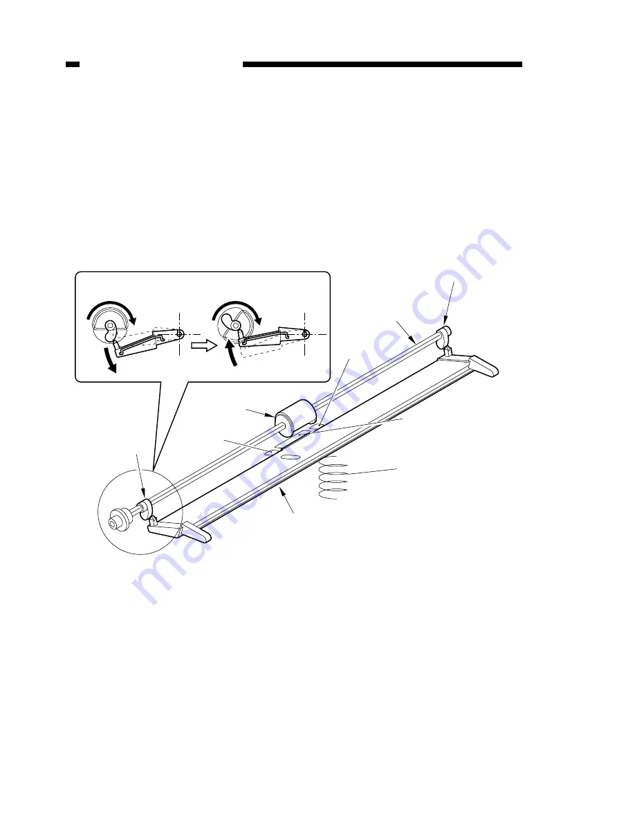
The mechanism for raising the lifting plate is illustrated in the diagram below.
During standby, the lifter plate is supported and lowered by the cams fitted onto the
front and rear of the multi-feeder pick-up roller.
When the paper roller rotates, the cams are also made to rotate, causing the lifter
plate to rise, and the paper set in the multi-feeder comes into contact with multi-feeder
pick-up roller.
A separation pad and sub pad are fitted onto the pick-up roller’s facing surface, and
through the separation process, only one sheet of paper is fed at a time to the main unit.
Figure 7-402
Cam
Cam
Multi-feeder
pick-up roller
Lifter plate
Lifter plate
in the lowered position
Lifter plate
in the raised position
Multi-feeder pick-up
roller drive axis
Separation
sub pad
Separation
sub pad
Separation pad
Lifter plate push-up spring
Summary of Contents for GP160DF
Page 6: ...COPYRIGHT 1999 CANON INC CANON GP160 REV 0 FEB 1999 PRINTED IN JAPAN IMPRIME AU JAPON iv...
Page 12: ......
Page 52: ......
Page 64: ......
Page 74: ......
Page 86: ......
Page 88: ......
Page 98: ......
Page 108: ......
Page 110: ......
Page 146: ......
Page 148: ......
Page 158: ......
Page 186: ......
Page 188: ......
Page 204: ......
Page 206: ......
Page 224: ......
Page 232: ......
Page 234: ......
Page 430: ......
Page 432: ......
Page 434: ...A 2 COPYRIGHT 1999 CANON INC CANON GP160 REV 0 FEB 1999 PRINTED IN JAPAN IMPRIME AU JAPON...
Page 436: ......
Page 482: ......
Page 622: ......
Page 623: ......
Page 625: ......
Page 627: ......
Page 635: ......


