3-28
COPYRIGHT © 1999 CANON INC.
CANON GP605/605V REV.0 JAN. 1999 PRINTED IN JAPAN (IMPRIME AU JAPON)
CHAPTER 3 ORIGINAL EXPOSURE SYSTEM
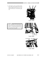
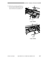
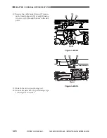
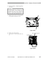
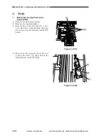
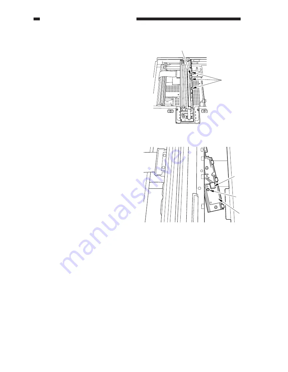
Figure 3-C501
Figure 3-C502
Claw
[1]
[2]
[3]
[4]
C.
PCBs
1.
Removing the Light Intensity
Control PCB
1) Remove the right glass retainer.
2) Remove the copyboard glass.
3) Remove the screw [1] from the No. 1 mir-
ror mount; then, while pushing down the
three claws, free the intensity control PCB
holder.
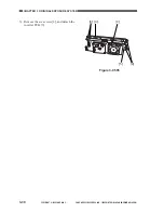
4) Disconnect the connector [2] (J165), and
remove the screw [3]; then, detach the
light intensity control PCB [4].
Summary of Contents for GP605
Page 3: ......
Page 4: ......
Page 24: ......
Page 56: ......
Page 78: ......
Page 116: ......
Page 124: ......
Page 148: ......
Page 150: ......
Page 168: ......
Page 170: ......
Page 250: ......
Page 252: ......
Page 342: ......
Page 390: ......
Page 392: ......
Page 464: ......
Page 466: ......
Page 512: ......
Page 514: ......
Page 572: ......
Page 574: ......
Page 590: ......
Page 592: ......
Page 854: ......
Page 870: ......
Page 874: ......

