COPYRIGHT © 1999 CANON INC.
CANON GP605/605V REV.0 JAN. 1999 PRINTED IN JAPAN (IMPRIME AU JAPON)
4-31
CHAPTER 4 IMAGE PROCESSING SYSTEM
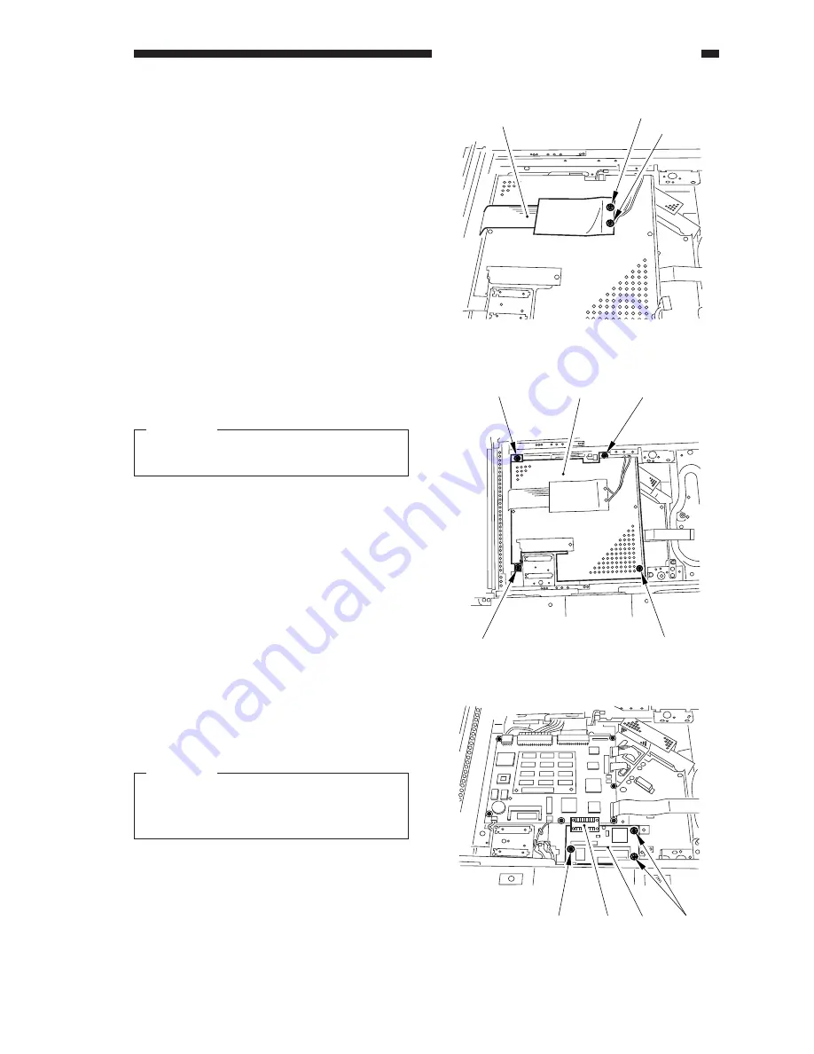
6) Remove the two screws [9], and detach
the flat cable [10].
7) Remove the four screws [11], and detach
the image processor cover [12].
Caution:
Take care not to damage the flat cable re-
moved in step 6).
8) Remove the three screws [13], and detach
the original orientation detection PCB
[14].
Caution:
Take care not to damage the connector
[15] of the image processor PCB and the
original orientation detection PCB [14].
Figure 4-D410
Figure 4-D411
[10]
[9]
[9]
[11]
[11]
[12]
[11]
[11]
Figure 4-D412
[13]
[13]
[15] [14]
Summary of Contents for GP605
Page 3: ......
Page 4: ......
Page 24: ......
Page 56: ......
Page 78: ......
Page 116: ......
Page 124: ......
Page 148: ......
Page 150: ......
Page 168: ......
Page 170: ......
Page 250: ......
Page 252: ......
Page 342: ......
Page 390: ......
Page 392: ......
Page 464: ......
Page 466: ......
Page 512: ......
Page 514: ......
Page 572: ......
Page 574: ......
Page 590: ......
Page 592: ......
Page 854: ......
Page 870: ......
Page 874: ......


