CHAPTER 5 LASER EXPOSURE SYSTEM
5-10
COPYRIGHT © 1999 CANON INC.
CANON GP605/605V REV.0 JAN. 1999 PRINTED IN JAPAN (IMPRIME AU JAPON)
C.
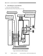
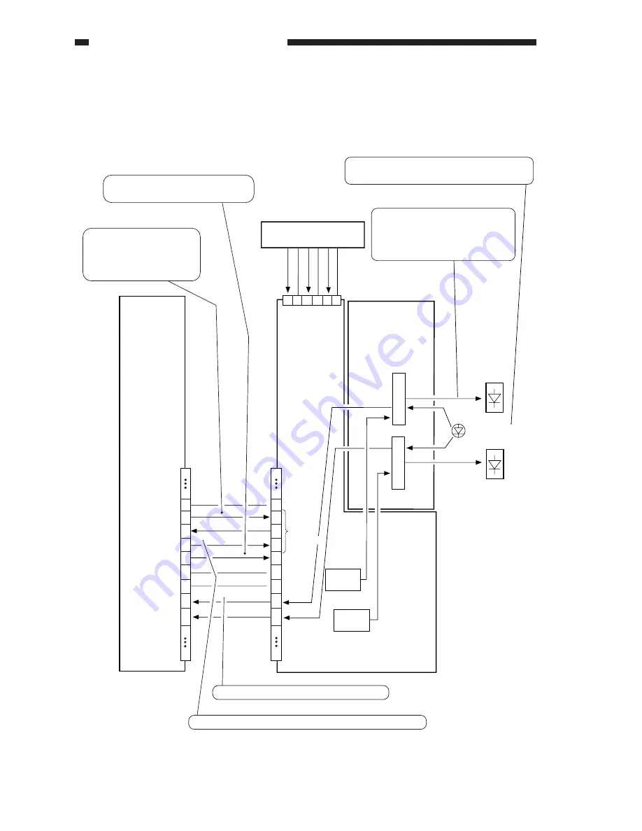
Controlling the Laser Intensity
The laser is controlled for the following:
[1] Laser power auto control (APC control).
[2] Intensity control to suit the surface potential of the drum.
Figure 5-302 Functional Block Diagram
Image processor PCB
J1107
1
9
10
11
12
13
14
15
16
17
18
19
30
GND
GND
GND
L-RDY-B
L-RDY-A
LD-DT1
LD-DT2
SK
Laser driver PCB 2
Laser driver PCB 1
1 2 3 4 5 6
Relay PCB
CS
Selects either laser A EEPROM
or laser B EEPROM for writing.
1
9
10
11
12
13
14
15
16
17
18
19
30
5V
8V
-8V
GND
GND
GND
J1714
J1301
J1354
LD-A
Laser B
Laser A
Intensity monitor
EEPROM
For laser A
EEPROM
For laser B
When the laser intently is as specified, '1'.
Clock pulses for writing to and reading from the EEPROM.
[1]-2
[2]-2
[2]-1
LD-B
To
EEPROM
[1]-1
The intensity is monitored, and a voltage
suited to the intensity is fed back.
The output is controlled so that
the voltage fed back and the
voltage from the EEPROM will
be identical.
The activation voltage
determined by potential
control is written into the
EEPROM.
Summary of Contents for GP605
Page 3: ......
Page 4: ......
Page 24: ......
Page 56: ......
Page 78: ......
Page 116: ......
Page 124: ......
Page 148: ......
Page 150: ......
Page 168: ......
Page 170: ......
Page 250: ......
Page 252: ......
Page 342: ......
Page 390: ......
Page 392: ......
Page 464: ......
Page 466: ......
Page 512: ......
Page 514: ......
Page 572: ......
Page 574: ......
Page 590: ......
Page 592: ......
Page 854: ......
Page 870: ......
Page 874: ......


