CHAPTER 7 PICK-UP/FEEDING SYSTEM
7-36
COPYRIGHT © 1999 CANON INC.
CANON GP605/605V REV.0 JAN. 1999 PRINTED IN JAPAN (IMPRIME AU JAPON)
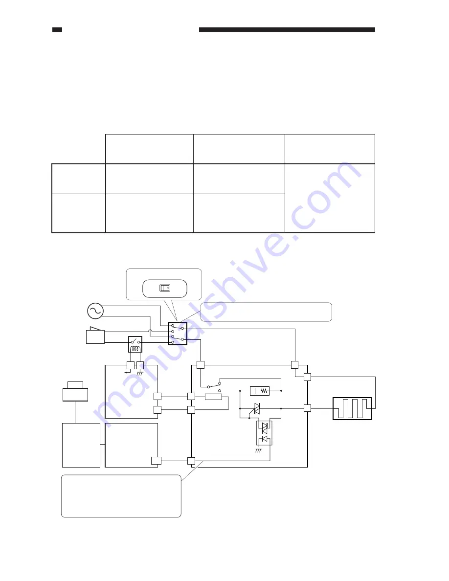
VI . CONTROLLING THE CASSETTE HEATER
The drive of the cassette heater is synchronized with either the outlet power supply or the
control panel power switch, selected by the heater switch (SW3).
While the copier is operating (i.e., both power switch and control panel power switch are on),
the cassette heater ON signal (CASSETTE_HEATER_ON) controls the drive of the cassette heater
at all times.
Table 7-601
Figure 7-601 Block Diagram of the Cassette Heater Control Mechanisms
4
4
4
3
2
3
1
A8
J2601
J2604
1
J2605
J2601
J2602
J2602
GND
24V
Relay PCB
DC controller
PCB
MFC
PCB
Control panel
power switch
Cassette heater
(H4)
Q2604
Q2603
Z2602
RLY2602
J505
J1722
J1722
24V
Heater drier PCB
CASETTE_HEAT_ON
3
Heater switch
(SW3)
3
1
Main power
switch
From power
outlet
Relay
(RLY2)
Selects either power outlet sync or control
panel power switch sync.
OFF
ON
Heater switch (SW3)
When the cassette heater ON signal
goes '1', the cassette heater turns on.
When making double-side copies in a
low-humidity environment, '0';
otherwise, '1'.
Sync with
outlet power
supply (ON)
Sync with
control panel
paper supply
switch (OFF)
Main power switch OFF
Drives the cassette heater.
Stops the cassette heater.
Main power switch ON
Control panel power
switch OFF
Drives the cassette heater.
Stops the cassette heater.
Main power switch ON
Control panel power
switch ON
Drives the cassette heater
in response to the cassette
heater ON signal.
Summary of Contents for GP605
Page 3: ......
Page 4: ......
Page 24: ......
Page 56: ......
Page 78: ......
Page 116: ......
Page 124: ......
Page 148: ......
Page 150: ......
Page 168: ......
Page 170: ......
Page 250: ......
Page 252: ......
Page 342: ......
Page 390: ......
Page 392: ......
Page 464: ......
Page 466: ......
Page 512: ......
Page 514: ......
Page 572: ......
Page 574: ......
Page 590: ......
Page 592: ......
Page 854: ......
Page 870: ......
Page 874: ......


