COPYRIGHT © 1999 CANON INC.
CANON GP605/605V REV.0 JAN. 1999 PRINTED IN JAPAN (IMPRIME AU JAPON)
8-39
CHAPTER 8 FIXING SYSTEM
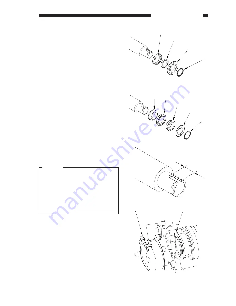
Figure 8-D506
Figure 8-D507
[12]
[11]
[10]
[9]
[16]
[15]
[17]
[14]
[13]
A
Figure 8-D509
Figure 8-D508
9) Remove the C-ring [9] at the front; then,
remove the gear [10], bushing [11], and
bearing [12].
10) Remove the C-ring [13] at the rear; then,
remove the electrode plate [14], spacer
[15], bearing [16], and bushing [17].
2.
Mounting the Upper Fixing Roller
Mount the upper roller by reversing the
steps used to remove it.
Caution:
a.
Remove it while taking care not to
soil or scratch the roller surface;
then, keep the roller in paper.
b.
Mount it so that the long cut-off A
shown in Figure 8-D508 is toward
the rear.
c.
When mounting it, clean the elec-
trode plate [1] and the electrode ter-
minal [2].
[2]
[1]
Summary of Contents for GP605
Page 3: ......
Page 4: ......
Page 24: ......
Page 56: ......
Page 78: ......
Page 116: ......
Page 124: ......
Page 148: ......
Page 150: ......
Page 168: ......
Page 170: ......
Page 250: ......
Page 252: ......
Page 342: ......
Page 390: ......
Page 392: ......
Page 464: ......
Page 466: ......
Page 512: ......
Page 514: ......
Page 572: ......
Page 574: ......
Page 590: ......
Page 592: ......
Page 854: ......
Page 870: ......
Page 874: ......


