COPYRIGHT © 1999 CANON INC.
CANON GP605/605V REV.0 JAN. 1999 PRINTED IN JAPAN (IMPRIME AU JAPON)
9-17
CHAPTER 9 EXTERNALS/AUXILIARY MECHANISMS
D.
Protective Functions
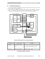
The copier is designed to automatically stop the output of the DC power supply as soon as the
overcurrent protective mechanism turns on.
If an overcurrent is detected by the overcurrent detection circuit A, outputs [1] and [2] are
stopped; this is to prevent malfunction of the copier, as output [1] is used by the logic system.
If the overcurrent detection circuit B detects an overcurrent, output [2] is stopped.
Figure 9-505 Protective Function Block Diagram
Table 9-504 Protective Functions
Output [1]
Converter
circuit 1
3.3V/5V/+8V
-8V/12V/15V
Converter
circuit 2
24V/38V
Sequence
control
circuit
Overcurrent
protection
circuit 1
Overcurrent
protection
circuit 2
Overcurrent
detection
circuit B
Overcurrent
detection
circuit A
5V
12V
3.3V
+8V
-8V
15V
38V
24V
Overcurrent detection signal 1
Overcurrent
detection signal 2
Output stop signal 2
Output stop signal 1
J1701
Output [2]
5
4
DC power supply PCB
Relay PCB
Outputs [1] and [2] are stopped.
Output [2] is stopped.
Detection by
Overcurrent
detection circuit A
Overcurrent
detection circuit B
Copier operation
Stops outputs [1] and [2]
from the DC power supply
PCB.
Stops output [2] from the
DC power supply PCB.
Resetting
Turn off the main power switch, and remove the
cause; then, leave the machine alone for about 3
min, and turn on the main power switch.
Remove the cause, and turn off and then on the
control panel power switch.
Summary of Contents for GP605
Page 3: ......
Page 4: ......
Page 24: ......
Page 56: ......
Page 78: ......
Page 116: ......
Page 124: ......
Page 148: ......
Page 150: ......
Page 168: ......
Page 170: ......
Page 250: ......
Page 252: ......
Page 342: ......
Page 390: ......
Page 392: ......
Page 464: ......
Page 466: ......
Page 512: ......
Page 514: ......
Page 572: ......
Page 574: ......
Page 590: ......
Page 592: ......
Page 854: ......
Page 870: ......
Page 874: ......


