COPYRIGHT © 1999 CANON INC.
CANON GP605/605V REV.0 JAN. 1999 PRINTED IN JAPAN (IMPRIME AU JAPON)
9-49
CHAPTER 9 EXTERNALS/AUXILIARY MECHANISMS
[3]
[4]
[4]
[4]
[2]
[1]
[5]
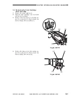
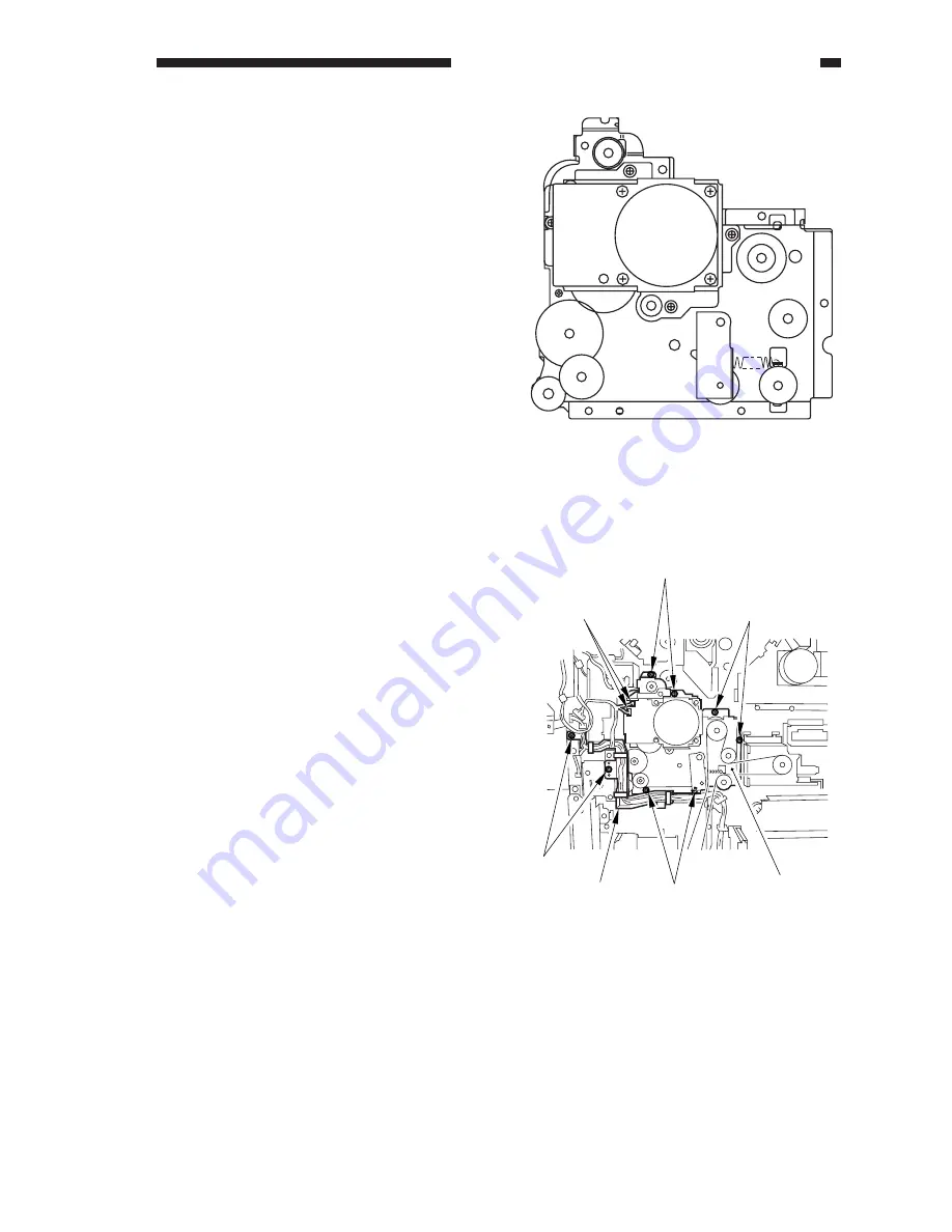
Figure 9-D702
2.
Removing the Pickup Drive
Assembly
Construction
1) Remove the rear cover.
2) Remove the high-voltage transformer
(DC). (See Figure 9-I701.)
3) Remove the flywheel.
4) Remove the drum gear.
5) Remove the waste toner pipe.
6) Remove the two screws [1], and loosen
the harness guide [2]; disconnect the two
connectors [3], and remove the six screws
[4]; then, detach the pickup drive assem-
bly [5].
Summary of Contents for GP605
Page 3: ......
Page 4: ......
Page 24: ......
Page 56: ......
Page 78: ......
Page 116: ......
Page 124: ......
Page 148: ......
Page 150: ......
Page 168: ......
Page 170: ......
Page 250: ......
Page 252: ......
Page 342: ......
Page 390: ......
Page 392: ......
Page 464: ......
Page 466: ......
Page 512: ......
Page 514: ......
Page 572: ......
Page 574: ......
Page 590: ......
Page 592: ......
Page 854: ......
Page 870: ......
Page 874: ......


