CHAPTER 13 TROUBLESHOOTING
13-50
COPYRIGHT © 1999 CANON INC.
CANON GP605/605V REV.0 JAN. 1999 PRINTED IN JAPAN (IMPRIME AU JAPON)
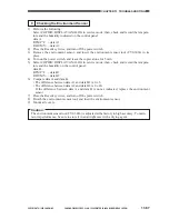
9) Fit the door switch auto control into the door switch assembly.
10) Turn on the power switch.
Caution:
Do not touch the potential sensor after turning on the power switch.
11) Select COPIER>DISPLAY>DPOT>DPOT-K in service mode, and check that the reading dur-
ing initial rotation is between 0 and 30.
Reference:
1. If the result in method 1 is as indicated, and the result in method 2 is not as indicated,
suspect dirt on the sensor or a fault in the potential measurement unit.
2. If the results in method 1 and method 2 are as indicated,
assume that the signal path from the potential sensor unit to the microprocessor on the DC
controller PCB is normal and the operation in general is also normal.
12) Turn off the power switch.
13) Detach the potential sensor meter electrode.
14) Mount the potential sensor support plate.
15) Turn on the power switch.
Summary of Contents for GP605
Page 3: ......
Page 4: ......
Page 24: ......
Page 56: ......
Page 78: ......
Page 116: ......
Page 124: ......
Page 148: ......
Page 150: ......
Page 168: ......
Page 170: ......
Page 250: ......
Page 252: ......
Page 342: ......
Page 390: ......
Page 392: ......
Page 464: ......
Page 466: ......
Page 512: ......
Page 514: ......
Page 572: ......
Page 574: ......
Page 590: ......
Page 592: ......
Page 854: ......
Page 870: ......
Page 874: ......


