COPYRIGHT © 1999 CANON INC.
CANON GP605/605V REV.0 JAN. 1999 PRINTED IN JAPAN (IMPRIME AU JAPON)
13-103
CHAPTER 13 TROUBLESHOOTING
63
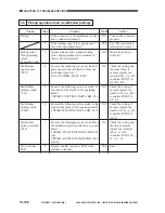
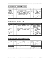
The DC power supply fails to operate 1.
Step
1
2
3
4
5
Action
See "The DC power
supply fails to operate
2."
See "AC power is
absent 2."
Correct the connection.
Remove the cause that
blew the fuse, and
replace the fuse.
Turn off the power
switch, and disconnect
the following
connectors from the
relay PCB: J1711,
J1712, J1714, J1716,
J1718.
Connect one of the
disconnected
connectors, and turn on
the power switch.
Repeat this for all
connectors to find the
connector that turns on
the protection circuit;
then, check the wiring
from that connector
and the DC loads.
Replace the DC power
supply PCB.
Checks
Is the main power lamp on?
Is there the rated voltage between J28-1
and J28-5 and between J28-2 and J28-7
on the DC power supply PCB?
Is the connection of the cable for the
connector (J1701-4 for overcurrent
detection signal 1) on the relay PCB
normal?
Is the fuse (FU101) on the DC power
supply PCB blown?
Turn off the main power supply switch.
When the power switch is turned on in
about 3 min, is the voltage between the
relay PCB and the following terminals
normal?
Note that the outputs in the table assume
that the AC input power has a tolerance of
±10%.
Yes/No
YES
NO
NO
YES
YES
NO
Connector
pin
No.
Output
voltage
Remarks
J1704
J1706
J1705
1
3
1
1
3
5
12V
3.3V
5V
+8V
-8V
15V
±7%,-10%
±5%
±4%
±10%
±10%
±10%
Cause
Control panel
power switch
AC power
supply
Wiring
Fuse (FU101)
Wiring, DC load
DC power
supply PCB
Summary of Contents for GP605
Page 3: ......
Page 4: ......
Page 24: ......
Page 56: ......
Page 78: ......
Page 116: ......
Page 124: ......
Page 148: ......
Page 150: ......
Page 168: ......
Page 170: ......
Page 250: ......
Page 252: ......
Page 342: ......
Page 390: ......
Page 392: ......
Page 464: ......
Page 466: ......
Page 512: ......
Page 514: ......
Page 572: ......
Page 574: ......
Page 590: ......
Page 592: ......
Page 854: ......
Page 870: ......
Page 874: ......


