COPYRIGHT © 1999 CANON INC.
CANON GP605/605V REV.0 JAN. 1999 PRINTED IN JAPAN (IMPRIME AU JAPON)
13-113
CHAPTER 13 TROUBLESHOOTING
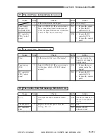
77
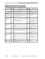
The Add Toner indicator fails to turn on.
Step
1
2
Action
Go to step 2.
1. Replace the sensor.
2. Replace the DC
controller PCB.
1. Replace the DC
controller PCB.
2. Replace the control
panel.
Checks
Is there toner inside the hopper?
Select COPIER>I/O>IP in service mode.
Move toner away from the toner sensor
(TS1) to exposure the sensor. At this time,
is bit 9 of P002 '0' (toner absent)?
Yes/No
YES
NO
YES
Cause
Toner sensor
(hopper), DC
controller PCB
DC controller
PCB, Control
panel
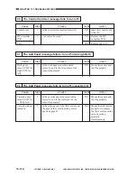
78
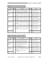
The Add Toner fails to turn on.
Step
1
2
Action
The toner inside the
hopper is not enough.
Supply toner.
1. Replace the toner
sensor inside the
hopper.
1. Replace the DC
controller PCB.
2. Replace the control
panel.
Checks
Is there toner at the rear of the hopper?
Select COPIER>I/O>IP in service mode.
At this time, is bit 9 of P002 '0' (toner
absent)?
Yes/No
NO
YES
NO
Cause
Toner
Toner sensor
(TS1)
DC controller
PCB Control
panel
79
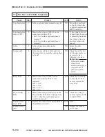
The Control Card Set message fails to turn on.
Step
1
2
Action
Check the connector of
the CC-V for a short
circuit.
End.
Replace the DC
controller PCB.
Checks
Can copies be made without a control
card?
Replace the control panel. Does the
message turn on?
Yes/No
YES
YES
NO
Cause
CC-V
Control panel
DC controller
PCB
Summary of Contents for GP605
Page 3: ......
Page 4: ......
Page 24: ......
Page 56: ......
Page 78: ......
Page 116: ......
Page 124: ......
Page 148: ......
Page 150: ......
Page 168: ......
Page 170: ......
Page 250: ......
Page 252: ......
Page 342: ......
Page 390: ......
Page 392: ......
Page 464: ......
Page 466: ......
Page 512: ......
Page 514: ......
Page 572: ......
Page 574: ......
Page 590: ......
Page 592: ......
Page 854: ......
Page 870: ......
Page 874: ......


