CHAPTER 13 TROUBLESHOOTING
13-122
COPYRIGHT © 1999 CANON INC.
CANON GP605/605V REV.0 JAN. 1999 PRINTED IN JAPAN (IMPRIME AU JAPON)
5
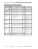
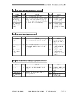
Cleaner Unit
Step
1
2
3
4
Action
Fit the transfer/
separation charging
assembly securely.
Adjust the height of the
charging wire.
Replace the separation
claw.
Advise the user to use
recommended paper.
1. Check the high-
voltage transformer.
2. Check the DC
controller PCB.
Checks
Is the transfer/separation charging
assembly and the pre-transfer charging
assembly fitted securely?
Is the height of the charging wire as
indicated?
Is the separation claw under the cleaner
unit damaged?
Try paper of a type recommended by
Canon.
Yes/No
NO
NO
YES
YES
NO
Cause
Transfer/
separation
charging
assembly,
Pre-transfer
charging
assembly
Separation claw
(cleaner unit)
Copy paper
High-voltage
transformer, DC
controller PCB
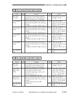
6
Lower Feeding Assembly
Step
1
2
3
Action
Set the assembly
correctly.
Replace CL16 or
CL17.
Replace PS14 or PS15.
Checks
Is the lower feeding assembly set
correctly?
Is the roller inside the lower feeding
assembly rotating?
Are the pre-confluence sensor (PS14) and
the post-confluence sensor (PS15)
normal?
Yes/No
NO
NO
NO
Cause
Lower feeding
middle clutch
(CL16), Lower
feeding right
clutch (CL17)
Pre-confluence
sensor (PS14),
Post-confluence
sensor (PS15)
Summary of Contents for GP605
Page 3: ......
Page 4: ......
Page 24: ......
Page 56: ......
Page 78: ......
Page 116: ......
Page 124: ......
Page 148: ......
Page 150: ......
Page 168: ......
Page 170: ......
Page 250: ......
Page 252: ......
Page 342: ......
Page 390: ......
Page 392: ......
Page 464: ......
Page 466: ......
Page 512: ......
Page 514: ......
Page 572: ......
Page 574: ......
Page 590: ......
Page 592: ......
Page 854: ......
Page 870: ......
Page 874: ......

