COPYRIGHT © 1999 CANON INC.
CANON GP605/605V REV.0 JAN. 1999 PRINTED IN JAPAN (IMPRIME AU JAPON)
13-205
CHAPTER 13 TROUBLESHOOTING
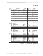
Items under COPIER>ADJUST
Level 1
Level 2
Level 3
Range
Description
ADJUST
LAMP
L-DATA
0 to 255
Use it to adjust the scanning lamp intensity data.
AE
AE-TBL
1 to 9
Use it to adjust the text density for AE mode with priority
on speed.
ADJ-XY
ADJ-X
0 to 2970
Use it to adjust the image leading edge position.
ADJ-Y
360 to 1360
Use it to adjust the CCD image read start position
(main scanning direction).
ADJ-S
0 to 4
Use it to adjust the scanner home position.
CCD
GAIN-E
80 to 160
Use it to adjust the CCD even-number photocell gain.
GAIN-O
80 to 160
Use it to adjust the CCD odd-number photocell gain.
OFST-E
1 to 254
Use it to adjust the CCD even-number photocell offset.
OFST-O
1 to 254
Use it to adjust the CCD odd-number photocell offset.
SH-TRGT
1 to 511
Use it to set the white level target value for shading
correction.
LASER
PVE-OFST
-300 to 300
Use it to adjust the offset from the center of the laser.
LA-DELAY
450 to 550
Use it to enter the laser delay value for the laser unit.
LA-PWR-A
48 to 432
Use it to set the laser A power adjustment value.
LA-PWR-B
48 to 432
Use it to set the laser B power adjustment value.
IP-DELAY
5 to 25
Use it to set the laser delay value for the IP PCB.
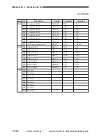
DEVELOP
DE-DC
0 to 500
Use it to set the developing DC output adjustment value
for image exposure.
DE-NO-DC
0 to 500
Use it to set the developing DC output adjustment value
for image exposure.
DE-OFST
-50 to 50
Use it to adjust the offset for the image bias DC component.
DENS
DENS-ADJ
1 to 9
Use it to adjust copy density.
BLANK
BLANK-T
0 to 2362
Use it to set the leading edge non-image width.
BLANK-B
0 to 2362
Use it to set the trailing edge non-image width.
V-CONT
EPTOTOFST
0 to 255
Use it to set the potential sensor offset.
VL-OFST
-5 to 5
Use it to set the light area potential target value offset.
VD-OFST
-5 to 5
Use it to set the dark area potential target value offset.
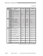
HV-PRI
GRID
400 to 900
Use it to set the primary charging assembly grid bias
output adjustment value.
HV-TR
TR-N1
-650 to -150
Use it to set the transfer charging output adjustment value
(1st side).
TR-N2
-650 to -150
Use it to set the transfer charging output adjustment value
(2nd side).
PRE-TR
0 to 300
Use it to set the output adjustment value for the
pre-transfer charging assembly.
HV-SP
SP-N1
0 to 500
Use it to set the separation charging output adjustment
value (1st side).
SP-N2
0 to 500
Use it to set the separation charging output adjustment
value (2nd side).
Summary of Contents for GP605
Page 3: ......
Page 4: ......
Page 24: ......
Page 56: ......
Page 78: ......
Page 116: ......
Page 124: ......
Page 148: ......
Page 150: ......
Page 168: ......
Page 170: ......
Page 250: ......
Page 252: ......
Page 342: ......
Page 390: ......
Page 392: ......
Page 464: ......
Page 466: ......
Page 512: ......
Page 514: ......
Page 572: ......
Page 574: ......
Page 590: ......
Page 592: ......
Page 854: ......
Page 870: ......
Page 874: ......


