CHAPTER 3 ORIGINAL EXPOSURE SYSTEM
3-10
COPYRIGHT © 1999 CANON INC.
CANON GP605/605V REV.0 JAN. 1999 PRINTED IN JAPAN (IMPRIME AU JAPON)
B.
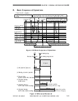
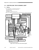
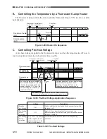
Controlling the Temperature by a Fluorescent Lamp Heater
The fluorescent lamp controls the area around the fluorescent lamp to 70°C to ensure a stable
light intensity.
Figure 3-302 Heater-On Sequence
C.
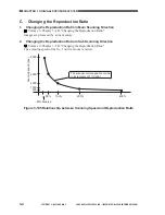
Controlling Pre-Heat Voltage
A pre-heat voltage is applied to the fluorescnet lamp even when the lamp remains off so as to
ensure an optimum intensity in the shortest time possible.
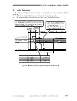
Figure 3-303 Pre-Heat Voltage Application Sequence
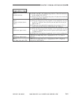
Table 3-301 Pre-Heat Voltage
Main power
switch ON
Control panel
switch ON
Copy Start
key ON
INTR
WMUP WMUPR
SLEEP
LSTR
STBY
SCFW
SCRV
STBY
Controlled
to 70˚C
Controlled to 70˚C
Initial
activation
70˚C
Fluorescent heater
(H5)
Scanning lamp
(FL1)
Main power
switch ON
Control panel
power switch ON
Copy Start
key ON
Original set
INTR
LSTR
STBY
STBY
Controlled to 70˚C
Controlled to 70˚C
1.5
sec
1.5
sec
70˚C
2.9V
2.9 V
4.1V
2.9V
4.1V
Intensity
check
Optimum value
WMUP
WMUPR
SLEEP
SCFW
SCRV
Optimum
value
Scanning lamp
(FL1)
Scanning lamp
pre-heat voltage
Fluorescent heater
(H5)
Continued application of pre-heat voltage
would hinder temperature control;
therefore, it is turned off and on in
conjunction with the scanner heater.
The intensity of light is checked by the intensity sensor to
determine the optimum level based on the measurement.
The scanning lamp is assumed to
have reached its optimum intensity
when the temperature of the area
around it reaches 70˚C. Then, the
pre-heat voltage is increased to
prepare for activation.
Voltage
2.9 V
4.1 V
Description
Used to stabilize the heat inside the fluorescent lamp while
the lamp is off.
Pre-heating
during
activation
3.9 V to 3.8 V (optimum
level is applied to suit
the measurement of the
light intensity sensor)
Standby
pre-heating
Pre-heating
before
activation
Applied 1.5 sec immediately before turning on the
fluorescent lamp, thereby shortening the time until optimum
intensity is attained.
To stabilize the inside of the fluorescent lamp during
activation.
Summary of Contents for GP605
Page 3: ......
Page 4: ......
Page 24: ......
Page 56: ......
Page 78: ......
Page 116: ......
Page 124: ......
Page 148: ......
Page 150: ......
Page 168: ......
Page 170: ......
Page 250: ......
Page 252: ......
Page 342: ......
Page 390: ......
Page 392: ......
Page 464: ......
Page 466: ......
Page 512: ......
Page 514: ......
Page 572: ......
Page 574: ......
Page 590: ......
Page 592: ......
Page 854: ......
Page 870: ......
Page 874: ......

