COPYRIGHT © 1999 CANON INC.
CANON GP605/605V REV.0 JAN. 1999 PRINTED IN JAPAN (IMPRIME AU JAPON)
3-17
CHAPTER 3 ORIGINAL EXPOSURE SYSTEM
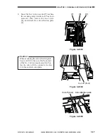
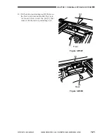
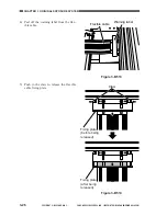
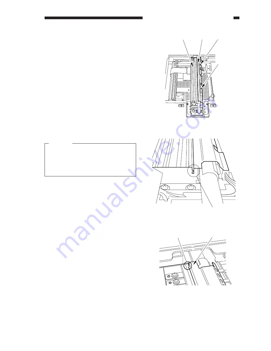
Figure 3-A504
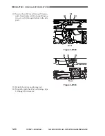
Figure 3-A505
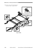
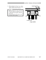
Figure 3-A503
[8]
[9]
[7]
[8]
Cut-off (front)
Anti-reflection plate
Cut-off (rear)
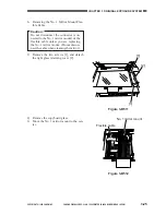
3) Move the No. 1 mirror mount [7] to where
the scanning lamp inside cover has been
removed; then, remove the two screws
[8], and detach the anti-reflection plate
[9].
Caution:
When mounting the anti-reflection plate,
be sure to fit it in the cut-offs (front, rear)
of the No. 1 mirror mount securely. Fur-
ther, be sure to fit the connector in step
4) in the anti-refection plate.
Summary of Contents for GP605
Page 3: ......
Page 4: ......
Page 24: ......
Page 56: ......
Page 78: ......
Page 116: ......
Page 124: ......
Page 148: ......
Page 150: ......
Page 168: ......
Page 170: ......
Page 250: ......
Page 252: ......
Page 342: ......
Page 390: ......
Page 392: ......
Page 464: ......
Page 466: ......
Page 512: ......
Page 514: ......
Page 572: ......
Page 574: ......
Page 590: ......
Page 592: ......
Page 854: ......
Page 870: ......
Page 874: ......

