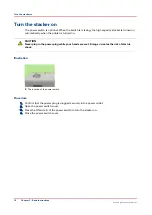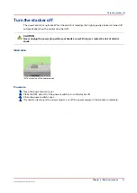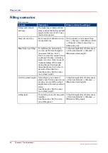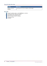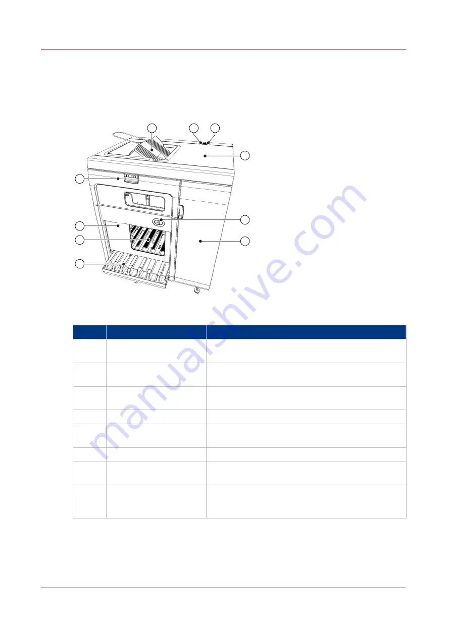
Description of the main parts
Illustration
1
7
4
10
9
3
2
8
6
5
[1] The main parts of High Capacity Stacker-H1
Main parts
Part
Description
1
Front door
The front door gives access to the registration unit and
the error locations A1-A7.
2
Front cover
The front cover gives access to the flip rings and error
location C1 (flip wheel).
3
Slide door
The slide door covers the tray and the stack inside the
stacker.
4
Top cover
The top cover gives access to the error locations B1-B5.
5
Power switch cover
The optional power switch cover shields the power
switch.
6
Power switch
The optional power switch turns the machine on or off.
7
Stacker control panel
The stacker control panel contains status LEDs, error
LEDs and the eject button.
8
Stack tray
The stack tray receives the prints and transfers the stack
of prints to the eject tray. After the transfer, the stack
tray moves back up and the filling can continue.
4
Description of the main parts
10
Chapter 2 - Parts and their function
Canon High Capacity Stacker-H1
Summary of Contents for High Capacity Stacker-H1
Page 1: ...Operation guide High Capacity Stacker H1 ...
Page 4: ...Contents 4 Canon High Capacity Stacker H1 ...
Page 5: ...Chapter 1 Preface ...
Page 8: ...Notes for the reader 8 Chapter 1 Preface Canon High Capacity Stacker H1 ...
Page 9: ...Chapter 2 Parts and their function ...
Page 15: ...Chapter 3 Basic instructions ...
Page 19: ...Chapter 4 Use the stacker ...
Page 29: ...Chapter 5 Troubleshooting ...
Page 31: ...Error location labels Chapter 5 Troubleshooting 31 Canon High Capacity Stacker H1 ...
Page 43: ...Chapter 6 Options ...
Page 46: ...Use the EasyLift to unload the stacker 46 Chapter 6 Options Canon High Capacity Stacker H1 ...
Page 47: ...Appendix A Specifications ...
Page 50: ...Index 50 Canon High Capacity Stacker H1 ...
Page 51: ......


