Chapter 6
6-1
6.1 Overview/Configuration
6.1.1 Configuration
0020-2691
i-SENSYS MF4300dn / i-SENSYS MF4350d / i-SENSYS MF4380dn / i-SENSYS MF4310/4318 / i-SENSYS MF4320d / i-SENSYS MF4330d / i-SENSYS
MF4340d / i-SENSYS D450d / i-SENSYS MF4370dn
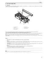
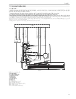
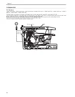
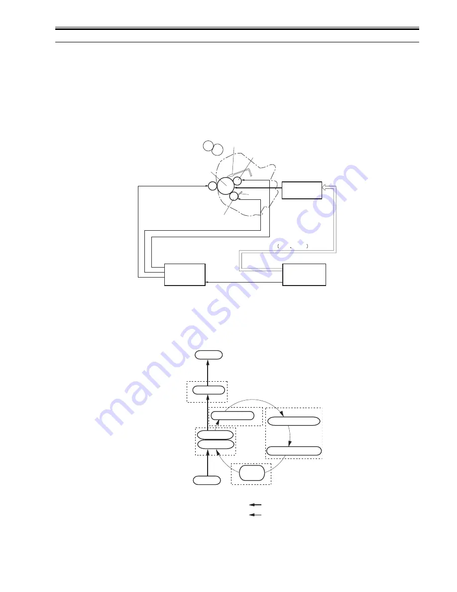
The image forming system is the core part of this machine, and is composed of the cartridge, the transfer charging roller, the fixing assembly, etc.
When receiving the print command from the SCNT PCB, the DCNT PCB activates the main motor to rotate the photosensitive drum, the developing cylinder, the
primary charging roller, the transfer charging roller and the pressure roller.
The surface of the photosensitive drum is evenly charged negative by the primary charging roller, and the laser beam converted with the video signal (VDO, /VDO)
is reflected to the surface of the photosensitive drum to form the latent image by the laser diode.
The latent image formed on the photosensitive drum is turned visible with the toner on the developing cylinder and is transferred on the paper by the transfer charg-
ing roller. The transferred toner turns into the permanent image on the paper when the heat and pressure are applied there at the fixing assembly. The cleaner blade
removes the residual toner on the surface of the photosensitive drum, whose potential is made even by the primary charging roller to be ready for the formation of
the next latent image.
F-6-1
6.1.2 Print Process
0020-2692
i-SENSYS MF4300dn / i-SENSYS MF4350d / i-SENSYS MF4380dn / i-SENSYS MF4310/4318 / i-SENSYS MF4320d / i-SENSYS MF4330d / i-SENSYS
MF4340d / i-SENSYS D450d / i-SENSYS MF4370dn
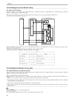
The print process shows the basic operation process for image formation by the printer.
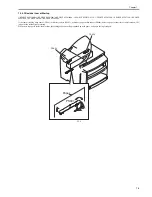
The print process of this machine has the main 5 blocks and 7 steps. The toner image is formed on papers by following the steps of each block.
The following is the outline of the blocks and steps of the print process.
F-6-2
1) Electrostatic latent image formation block
Electrostatic images are formed on the photosensitive drum.
Step1: Primary charging (Charges negative potential evenly on the surface of the photosensitive drum)
Step 2: Laser beam exposure (Forms electrostatic images on the photosensitive drum)
Laser /
scanner block
Cleaner blade
Photosensitive
drum
Primary charging roller
Cartridge
Blade
Developing cylinder
Transfer charging
roller
Fixing film area
DCNT PCB
Print command
Video signal
VDO
/VDO
PR1
TRS
DEV
SCNT PCB
Laser beam
6. Fixing
Drum cleaning
block
3. Devel
opment
Fixing block
Transfer block
Electrostatic latent
image formation block
2. Laser beam exposure
1. Primary charging
Delivery
Flow of paper
Direction of drum rotation
5. Separation
4. Transfer
7. Drum cleaning
Pick-up
Developing block
Summary of Contents for i-SENSYS MF4300dn
Page 1: ...Aug 22 2008 Service Manual MF4300 Series ...
Page 2: ......
Page 6: ......
Page 12: ...Contents 15 1 1 Solvents Lubricants Table 15 1 ...
Page 13: ...Chapter 1 Introduction ...
Page 14: ......
Page 16: ......
Page 32: ......
Page 33: ...Chapter 2 Basic Operation ...
Page 34: ......
Page 36: ......
Page 38: ......
Page 39: ...Chapter 3 Original Exposure System ...
Page 40: ......
Page 42: ......
Page 44: ...Chapter 3 3 2 F 3 1 ...
Page 49: ...Chapter 4 Original Feeding System ...
Page 50: ......
Page 52: ......
Page 55: ...Chapter 4 4 3 F 4 6 ...
Page 66: ......
Page 67: ...Chapter 5 Laser Exposure ...
Page 68: ......
Page 70: ......
Page 73: ...Chapter 5 5 3 ...
Page 76: ......
Page 77: ...Chapter 6 Image Formation ...
Page 78: ......
Page 80: ......
Page 85: ...Chapter 7 Pickup and Feed System ...
Page 86: ......
Page 88: ......
Page 96: ......
Page 97: ...Chapter 8 Fixing System ...
Page 98: ......
Page 100: ......
Page 108: ......
Page 109: ...Chapter 9 External and Controls ...
Page 110: ......
Page 112: ......
Page 121: ...Chapter 10 Maintenance and Inspection ...
Page 122: ......
Page 124: ......
Page 128: ......
Page 129: ...Chapter 11 Measurement and Adjustments ...
Page 130: ......
Page 132: ......
Page 135: ...Chapter 12 Correcting Faulty Images ...
Page 136: ......
Page 138: ......
Page 144: ...Chapter 12 12 6 2 DCNT PCB 3 Power supply PCB 4 High voltage PCB SW301 Interlock switch ...
Page 145: ...Chapter 13 Error Code ...
Page 146: ......
Page 147: ...Contents Contents 13 1 Error Code 13 1 13 1 1 Error Code Outline 13 1 13 1 2 Error Code 13 1 ...
Page 148: ......
Page 153: ...Chapter 14 Service Mode ...
Page 154: ......
Page 156: ...Contents 14 3 2 3 Sensor test 14 16 14 3 2 4 Key test 14 16 ...
Page 174: ......
Page 175: ...Chapter 15 Service Tools ...
Page 176: ......
Page 177: ...Contents Contents 15 1 Service Tools 15 1 15 1 1 Solvents Lubricants Table 15 1 ...
Page 178: ......
Page 180: ......
Page 181: ...Aug 22 2008 ...
Page 182: ......


