background image

Controller System

 Removing the Controller Cover

■ Preparation

1.

“Removing the Rear Cover Unit” on page 127

2. Remove the cassette.

3.

“Removing the Cartridge” on page 127

4.

“Removing the Right Cover Unit” on page 129

■ Procedure

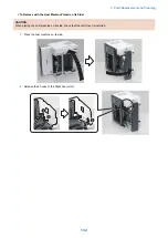
1. Remove the Controller Cover.

4x

4x

 Removing the Main Controller PCB

■ Preparation

CAUTION:

“Before Replacing the Main Controller PCB” on page 178

1.

“Removing the Rear Cover Unit” on page 127

2. Remove the cassette.

3.

“Removing the Cartridge” on page 127

4.

“Removing the Right Cover Unit” on page 129

5.

“Removing the Controller Cover” on page 140

5. Parts Replacement and Cleaning

140

Summary of Contents for imageCLASS LBP325dn

Page 1: ...SERVICE MANUAL imageCLASS LBP325dn Canon February 23 2021 Rev 5 COPYRIGHT 2021 CANON INC CANONimageCLASSLBP325dn Rev 5 PRINTED IN U S A...

Page 2: ...demarks and service marks of Mopria Alliance Inc in the United States and other countries Unauthorized use is strictly prohibited Apple AppleTalk Bonjour iPad iPhone iPod touch Mac OS X and Safari are...

Page 3: ...The following symbols are used throughout this Service Manual Symbols Explanation Symbols Explanation Check 1x Remove the claw Check visually 1x Insert the claw Check a sound Push the part 1x Disconn...

Page 4: ...nal is High while 0 is used to indicate Low The voltage value however differs from circuit to circuit In addition the asterisk as in DRMD indicates that the DRMD signal goes on when 0 In practically a...

Page 5: ...Product Lineup 6 Host machine 6 Options 6 Features 7 Specifications 8 Product Specifications 8 Paper Type 9 Paper Size 9 Parts Name 11 Front side of the machine 11 Rear Side of the Host Machine 12 In...

Page 6: ...41 Skew Correction 42 Paper Width Detection 43 Paper Length Detection 44 Feed Speed Control 44 Delivery Tray Full Detection 45 Jam Detection 45 3 Technical Explanation System 48 Version Upgrade 49 Ove...

Page 7: ...the Fixing Power Supply PCB 146 Removing the Low Voltage Power Supply Unit 149 Removing the High Voltage Power Supply PCB 149 Removing the Control Panel Unit 150 Removing the Control Panel Unit Key P...

Page 8: ...Cassette 1 lift up error 197 E015 0002 Cassette 2 Option Cassette 1 lift up error 197 E015 0003 Cassette 3 Option Cassette 2 lift up error 198 E015 0004 Cassette 4 Option Cassette 3 lift up error 198...

Page 9: ...ce access error 201 E602 1602 File system could not be initialized normally CDS related 202 E602 1612 Device access error CDS related 202 E602 1613 Device access error CDS related 202 E604 0000 Insuff...

Page 10: ...0 Remote UI Service Mode 210 Service Report 211 Service Mode 214 ADJUST GR 214 OPTION GR 215 CRGMNG GR 217 FUNCTION GR 219 LOG GR 224 PANEL LOCK GR 225 F W UPDATE GR 225 NETWORK GR 226 SP ADMIN MODE 2...

Page 11: ...Safety Precautions Laser 2 Power Supply Lithium Battery 3 Toner Safety 3 Notes on works 4...

Page 12: ...the beam may cause eye injuries Therefore be sure not to disassemble the laser scanner unit No adjustment can be made to the laser scanner unit in the machine in the field The mark or the warning lab...

Page 13: ...es according to the instructions CAUTION Risk of explosion if battery is replaced by an incorrect type The following warnings are given to comply with Safety Principles EN60950 1 CAUTION Wenn mit dem...

Page 14: ...forming cleaning using organic solvent such as alcohol be sure to check that the component of solvent is vaporized completely before assembling Notes on Assembly Disassembly Follow the items below to...

Page 15: ...Product Overview 1 Product Lineup 6 Features 7 Specifications 8 Parts Name 11...

Page 16: ...Yes Yes Wired LAN Yes Yes Yes Yes Wireless LAN PDL Function LBP325dn LBP325x LBP324x LBP323x PS Yes Yes UFR II Yes Yes Yes Yes PCL Yes Yes Yes Options Name Description Paper Feeder PF C1 A Paper Feede...

Page 17: ...high volume printing as up to 3 Paper Feeders can be installed in addition to the Multi purpose Tray and Standard Cassette Up to 2 300 sheets 80 g m 2 or 2 660 sheets 64 g m 2 can be continuously and...

Page 18: ...rinting 43 pages min A4 45 5 pages min LTR At 2 sided printing 36 pages min A4 37 8 pages min LTR Warm up time 2 Quick startup OFF 30 seconds or less Quick startup ON 3 seconds or less Recovery time 3...

Page 19: ...the print environment 4 This may vary depending on the site environment and the type of paper used 5 Excluding the Toner Cartridge Paper Type Yes Pickup possible Pickup not possible Type of paper Pape...

Page 20: ...x Card 3 x 5 76 2 mm x 127 0 mm Yes Envelope No 10 COM10 104 7 mm x 241 3 mm Yes Envelope Monarch 98 4 mm x 190 5 mm Yes Envelope C5 162 0 mm x 229 0 mm Yes Envelope DL 110 0 mm x 220 0 mm Yes Custom...

Page 21: ...o Name No Name 1 Output Tray 7 Power Switch 2 Front Cover Open Button 8 Paper Stopper 3 Ventilation opening 9 Front Cover 4 Handle for carrying 10 Pickup Cassette 5 Multi purpose Tray 11 USB Port for...

Page 22: ...6 7 8 9 10 3 No Name No Name 1 Rear Cover 6 USB Port for USB appliances 2 Rating name plate label 7 USB Port for PC connection 3 Ventilation opening 8 ACT Lamp 4 Power Socket 9 LNK Lamp 5 SD Card Slo...

Page 23: ...the Host Machine 1 3 1 2 3 No Name No Name 1 Transport Guide Rear 3 Duplex Transport Guide 2 Transport Guide Front Cross Section View 1 2 3 4 5 6 7 8 9 10 12 14 18 19 21 15 13 16 20 17 11 1 Product Ov...

Page 24: ...Registration Shutter 20 Duplex Feed Roller 10 Multi purpose Tray Pickup Roller 21 Pressure Roller 11 Multi purpose Tray Separation Pad Control Panel 5 1 1 2 4 3 5 6 7 8 9 10 11 12 13 14 19 16 17 18 20...

Page 25: ...Technical Explanation Device 2 Basic Configuration 16 Controller System 17 Laser Exposure System 25 Image Formation System 27 Fixing System 33 Pickup Feed System 36...

Page 26: ...ystem Pickup Feed System Fixing System Image Formation System Laser Exposure System Drum Laser scanner Duplex Feed System Main controller DC controller Controller System Laser beam Paper flow simplex...

Page 27: ...ontrollers 2 1 No Parts name Function 1 Main Controller PCB Provides controls on the system image processing and network and maintain various setting values 2 DC Controller PCB Provides controls on pr...

Page 28: ...J1120 Control Panel PCB J1016 SOFT ID PCB J1128 Memory PCB J1004 USB Front J110 SD Card Slot J200 USB TypeA J6 USB TypeA J106 USB TypeB J2 LAN J807 Power Switch J808 DC Controller PCB J201 DC Control...

Page 29: ...Pickup Solenoid J144 Cassette Pickup Solenoid Lifter Motor J146 Main Motor J147 Main Fan J151 TOP Sensor Paper Width Sensor Duplex Feed Sensor J152 Delivery Tray Full Level Sensor Fixing Delivery Sens...

Page 30: ...ller Cassette Feed Roller Registration Roller Vertical Path Roller Scanner Motor M3 Scanner Mirror Lifter Motor M4 Lifter in the cassette Fan Control This machine uses 2 fan motors for preventing temp...

Page 31: ...ect whether the Front Cover is opened or closed SW5 Rear Cover Switch To detect whether the Rear Cover is opened or closed Power supply This circuit is for converting the AC power supply input from th...

Page 32: ...24VB and 24VC which stop supplying power when the Front Cover is opened Protection function The Low Voltage Power Supply has functions to protect against overcurrent and overvoltage to prevent damage...

Page 33: ...outlet and perform the work Reset Shut Down Yes A shutdown can be performed by pressing the Main Power Switch for at least 5 seconds but this is not recommended because the power may be turned OFF bef...

Page 34: ...nel engine and controller are turned OFF Only Power LED lights up Conditions for Not Entering Deep Sleep The machine does not enter deep sleep when any of the following conditions are met When a job i...

Page 35: ...W 3KRWRVHQVLWLYH GUXP 6 11 5 02725 63 21752 VLJQDO FRQWUROOHU 9 2 VLJQDO 1387 VLJQDO 0DLQ FRQWUROOHU 6 5 21752 VLJQDO Failure Detection Overview The DC Controller detects the following failures in the...

Page 36: ...E110 0000 Error in the initial operation of the Scanner Motor E110 0001 Error in rotation of the Scanner Motor 2 Technical Explanation Device 26...

Page 37: ...loping 1 Primary charging Pickup 4 Transfer 5 Separation Transfer Latent image formation Media path Direction of the drum rotation Block Step Drum cleaning Developing Latent image formation block Duri...

Page 38: ...ge The drum discharge is performed during LSTR period 3KRWRVHQVLWLYH UXP DVHU HDP Developing block Toner adheres to the electrostatic latent image on the photosensitive drum which becomes visible Step...

Page 39: ...vature of the photosensitive drum cause the media to separate from the drum surface The static charge eliminator reduces back side static discharge of the media for stable media feed and image quality...

Page 40: ...esidual toner off the surface of the photosensitive drum The residual toner is deposited in the toner collection box Toner collection box Photosensitive drum Cleaning blade Cartridge Overview The cart...

Page 41: ...the cartridge memory cannot be detected Cannot print Cart may be non canon counterfeit is displayed Cartridge Detection The DC Controller detects whether a cartridge is installed according to the pres...

Page 42: ...n Utility Menu Consumables Remaining Toner Remaining Toner 2 Value set in Setup User Maintenance Toner Check Timing Specify Check Timing 3 Continue Printing or Stop Printing can be set in Control Menu...

Page 43: ...Heater for heating the Fixing Film Thermistor TH1 Thermistor for detecting the fixing temperature Contact type Thermoswitch TP1 Thermoswitch for preventing the abnormal temperature rise of the Fixing...

Page 44: ...ety circuit Thermoswitch The following explains each of the functions 1 DC Controller The DC Controller monitors the detected temperatures of the Main Thermistor TH1 The DC Controller stops the fixing...

Page 45: ...rature of the thermistor does not rise although a specified period of time has passed since the heater was turned ON Abnormally high fixing temperature detection When a Thermistor reaches a certain te...

Page 46: ...machine The pickup feed and delivery systems consist of the following three blocks Pickup Feed From each pickup slot to the inlet of the Fixing Assembly Fixing Delivery From the Fixing Assembly to th...

Page 47: ...r 3 Fixing Film 4 Photosensitive Drum 5 MP tray Pickup roller 6 Vertical Path Roller 7 Cassette Feed Roller 8 Cassette Separation Roller 9 Cassette Pickup Roller 10 Duplex Re pickup Roller 11 Registra...

Page 48: ...SL1 SL3 M1 CL2 Symbol Name M1 Main Motor M2 Pickup Motor M4 Lifter Motor CL2 Duplex Re pickup Clutch SL1 Cassette Pickup Solenoid SL2 Duplex Reverse Solenoid SL3 Multi purpose Tray Pickup Solenoid 2 T...

Page 49: ...or PS21 Paper Width Sensor PS22 Duplex Feed Sensor SW4 Cassette Detection Switch Lifter control Paper inside a cassette is lifted up by the Lifting Plate The Lifting Plate is lifted up by rotating the...

Page 50: ...ct the paper surface 2 Lift up operation during printing This operation is performed if the paper surface is lowered a certain amount by the pickup operation If the Cassette Paper Surface Sensor PS12...

Page 51: ...force transmitted to the Cassette Separation Roller becomes extremely weak Since force suppressing rotation is applied to the Cassette Separation Rollers of this machine this mechanism does not allow...

Page 52: ...e tray pickup solenoid control signal Pickup motor control signal Multi purpose tray media presence detection signal Skew Correction This machine can correct paper skew without lowering throughput Ske...

Page 53: ...th of paper being fed is detected by the Paper Width Sensor PS21 When the Paper Width Sensor Flags of the right and left are turned ON it is detected that the paper width is 210 mm or wider If the pap...

Page 54: ...etected to be shorter than the specified size image masking is performed from that point in time to prevent toner soiling of the Transfer Roller Feed Speed Control The printer changes the feed speed f...

Page 55: ...for a specified period of time during printing PS4 DC Controller Delivery Tray Delivery Sensor Lever Delivery Tray Sensor Paper Jam Detection The sensors are provided at the locations shown below to...

Page 56: ...r PS432 located between the PF Media Path Sensor PS432 and the TOP Sensor PS2 of the paper source failed to detect the paper leading edge Pickup Stationary Jam 1 The TOP Sensor PS2 does not detect the...

Page 57: ...llowing sensors TOP Sensor PS2 Paper Width Sensor PS21 Duplex Feed Sensor PS22 Pre registration Sensor PS11 Fixing Delivery Sensor PS13 PF Media Path Sensor PS432 Duplex Re pickup Delay Jam 1 At duple...

Page 58: ...Technical Explanation System 3 Version Upgrade 49 Backup Restoration 79 Monitoring Function e Maintenance imageWARE Remote 95 MEAP Application Management 101...

Page 59: ...tically download the firmware Version upgrade using a USB flash drive released only in special cases Upgrade the firmware of this machine using a USB flash drive Connect a USB flash drive where the fi...

Page 60: ...Installation Updater function enables users to distribute firmware through CDS via Internet Particularly on e Maintenance UGW enabled devices firmware can be updated remotely which effectively slashes...

Page 61: ...irmware b CDS Remote Download download in conjunction with UGW Firmware distribution can be performed before a service technician visits the customer by registering the distribution schedule in the de...

Page 62: ...lication Yes Installing system option Yes System Management Settings Yes Testing communications Yes Displaying update logs Yes Displaying system logs Yes Internal system error notification Notifying i...

Page 63: ...obs are not completed within 10 minutes If this occurs the error code 8x001106 will be returned different numbers will be shown for x depending on the execution modes Firmware update is executed if th...

Page 64: ...Confirm the URL setting of the distribution server UGW server set in the machine 1 Access the following URL from the browser on a PC connected to the same network as this machine and log in to the ma...

Page 65: ...Installation logs by MEAP application Logs related to enabled functions by system option Ordinary Er ror Yes Yes Yes Yes Logs for ordinary errors System Error Yes Yes Yes Yes Yes Logs for internal sys...

Page 66: ...CDS UGW 2 Access the Customer Information screen of the UGW WebPortal and specify Yes for the following setting Firmware Distribution CAUTION See imageWARE Remote Operator s Manual e Maintenance Busi...

Page 67: ...ICE MODE FUNCTION GR MEAP CDS MEAP When this setting is enabled Delivered Installation is displayed on Register Update Software screen in Settings Registration menu Displaying Update Firmware Menu on...

Page 68: ...distribution setting enabling automatic firmware download and update CAUTION Device without the function to wait for job completion Explain to the user in advance that a job cannot be accepted during...

Page 69: ...stribution to the target device NOTE For the operation procedure refer to CDS Scheduled Update in the CDS Operation Manual Firmware Distribution When the e mail notification setting is enabled on UGW...

Page 70: ...The procedure for checking a log is described below 1 Access the following URL from the browser on a PC connected to the same network as this machine and log in to the management screen https device...

Page 71: ...ocessing for deleting the firmware starts 4 Confirm that the Delete Firmware button is grayed out and deactivated Deleting a Scheduled Distribution Date Time This section describes the procedure for d...

Page 72: ...to the delivery server occurred Check if the network environment is correct to solve the cause of the error occurrence If the network environment of the device is correct obtain the log etc Refer to S...

Page 73: ...nication no response for 1min occurred After that retried but failed to connect to server Check the network environment of the device and re exe cute the job If it recurs obtain the log etc Refer to S...

Page 74: ...notice of version information Obtain the log etc Refer to System Management Opera tions under Version Upgrade of Updater in Trouble shooting of this manual and contact Support Div of the sales compan...

Page 75: ...cation test to analyze the cause of the error After solving the cause resend the order from the eRDS If it recurs obtain the log etc Refer to System Manage ment Operations under Version Upgrade of Upd...

Page 76: ...rsion Upgrade of Updater in Troubleshooting of this manual and contact Support Div of the sales company The delivery server stop ped Contact the sales company s Support Department After confirming res...

Page 77: ...g the characters which could not be used Do not specify E mail address with characters which cannot be used 19 Specify Com ments with up to 128 characters At the time of pe riodical update setting Com...

Page 78: ...remedy If the problem still persists clear the cache of the proxy server 3 If the symptom is not resolved by performing the foregoing remedy report it to the support department of the sales company w...

Page 79: ...ecessary search the applica ble firmware again and perform distribution of the firmware Tam ura Tam ura 81071001 A cancellation notification was sent to CDS when the dis tribution status was not corre...

Page 80: ...Applying Finished Failed Tam ura 8108100D When the distribution status was not correct schedule information was checked with CDS CDS has not been notified of the status change due to a network Tam ur...

Page 81: ...distribution but it could not be performed because the firmware to be distributed or the status of the device was changed Check the firmware to be distrib uted or the status of the device If necessary...

Page 82: ...ice Tam ura 1202 Specifying of scheduled update for a model that does not sup port scheduled update Contact the support department of the sales company Attach the Debug log and update log of the devic...

Page 83: ...o network cable connection device side Check the network environment If it occurs again contact the support de partment of the sales company Attach the Debug log and update log of the device Tam ura 4...

Page 84: ...start the operation again Tam ura 5103 No network cable connection device side Check the network environment of the de vice and start the operation again Tam ura 5201 Invalid HTTP request Contact the...

Page 85: ...t be re solved Tam ura Tam ura 520F The host name cannot be re solved when using a proxy server Tam ura Tam ura 5301 Failed to retrieve the data stream Contact the support department of the sales comp...

Page 86: ...tment of the sales company Attach the Debug log and update log of the device Tam ura 72xx An internal error in SMS Tam ura 7301 No existence of delivery ID Tam ura 7302 Invalid delivery ID Tam ura 730...

Page 87: ...red when the request has been made 81xxFFFE DB error General error to access DB 81xxFFFF DB error Internal error other than error to access DB file I O etc 8xxx1204 L CDS update process for a model th...

Page 88: ...ing the applicable firmware information Immediate download error dialog An internal error occurred at the time of request of firmware delivery information Free space in the storage destination disk ra...

Page 89: ...mation of service mode The DCM file is exported to a USB flash drive or PC local disk from the Control Panel or remote UI The exported DCM file can be returned to the original device or imported to a...

Page 90: ...an error 1 If the firmware version at the time of import differs from that at the time of export predetermined corrective processing may be performed 2 Predetermined corrective processing may be perfo...

Page 91: ...job is not allowed to be accepted during a processing In addition import export must not be performed during execution of a job Firmware must not be updated during an import export processing Fax cann...

Page 92: ...t basic setting data of menu options Service Mode Settings Select this check box to export various setting data of service mode MEAP Application Setting Information Select this check box to export the...

Page 93: ...e mode setting information file that was exported in the previous procedure 1 Enter service mode and set the following item to 1 SERVICE MODE FUNCTION GR SMD EXPT FUNCTION GR ECONF Import Export Set S...

Page 94: ...service mode and then check that the setting information is reflected This completes the procedure for importing a setting information file 7 Enter service mode and set the following item to 0 SERVICE...

Page 95: ...T Password fix OK key Entry Mode a Password Confirm fix OK key Entry Mode a 3 When the Import Export Set screen is displayed after the processing is complete press the Application button on the Contro...

Page 96: ...restart Press OK to close this screen is displayed when the processing is complete Press the OK key 4 When the machine has restarted press the Application key on the Control Panel select Remove USB M...

Page 97: ...2 Access the following service mode in the Remote UI from a PC browser specify the file to import enter the encryption password and click Start Importing SERVICE MODE FUNCTION GR Import Export Set IM...

Page 98: ...ion Target Data for Backup Settings Registration menu setting values Service mode setting values Backing Up to a USB Flash Drive This section describes the procedure for backing up to a USB flash driv...

Page 99: ...again after the export processing is complete ECONF EXPORT IMPORT Executing Done 4 Access service mode and confirm that the settings are reflected 5 Remove the USB flash drive Import Export Set IMPOR...

Page 100: ...achine install the Sublog Board to which data was exported attached with the Expansion ROM to an unused Main Controller PCB Install the above unused Main Controller PCB to the machine and turn ON the...

Page 101: ...e board and confirm that LED1 turns on LED1 SW1 If LED1 does not turn on You need change the battery on Sublog Board is located at BATS1 CR2032 CAUTION There is danger of explosion if the battery is r...

Page 102: ...mported to a once used PCB Therefore if a PCB from which the setting information is not exported backed up is connected to an unused Main Controller PCB backup data cannot be imported Backup Procedure...

Page 103: ...PCB 2 Install the unused Main Controller PCB to the machine and turn ON the power 3 Perform the following operation to write the information saved in the Sublog Board back to the machine 195 0 LPSRUW...

Page 104: ...VRAM read error Export cannot be executed because the faulty Main Controller PCB is too damaged to retrieve information Sublog R W error When the same data cannot be read 3 consecutive times due to Su...

Page 105: ...DS is embedded in the network module of the device and the front end module of the e Maintenance imageWARE Remote system is realized without requiring hardware besides the device Main Functions Functi...

Page 106: ...ent expires while the machine is in the sleep mode when only a stateless address is enabled transmission will fail immediately after the machine returns from the sleep mode When only a manual address...

Page 107: ...default value is the server URL Characters which can be set are as follows 01233456789ABCDEFGHIJKLMNOPQRSTUVWXYZabcdefghijklmnopqrstuvw xyz _ If ugwdevice net is not included in the character string w...

Page 108: ...TWORK GR E RDS REDUCE SEND NETHOD 4 Execute the following service mode to perform a communication test with the UGW server SERVICE MODE NETWORK GR E RDS COM TEST E RDS E RDS SWITCH RGW ADDRESS EGW POR...

Page 109: ...f the de vice 8700 0306 SRAM AeRDS version unmatch An invalid value has been entered at the beginning of the NVMEM area of E RDS nonvolatile memory area Turn OFF and then ON the power of the de vice 8...

Page 110: ...he proxy server Set the proxy server using the IP ad dress 8xxx 201E Proxy authentication error Proxy authentication error Check the user name and password for log ging in to the proxy and configure t...

Page 111: ...ice Java VM Device control class Libraries MEAP Platform MEAP Application MEAP Application System Services SMS Operating System CPCA Job control Touch Panel Composition UI control part Java VM Device...

Page 112: ...settings The PC and browser used to access SMS must meet the following conditions The supported browser language should be the same with the language of the OS Session cookie should be enabled The su...

Page 113: ...Print Manifest file of the MEAP application MeapSpecVersion SDK documents Mechanism MEAP platform judges whether MEAP applications can be operated on it using on the 2 information below DeviceSpecific...

Page 114: ...ed from LMS before reinstallation This specification aims to prevent misuse of applications To increase convenience of users only application with unlimited validity date and application counter e g P...

Page 115: ...res If the status of the license is none this item will not be printed License Upper Limit It indicates the limit imposed on individual counter readings If the status of the license is none this item...

Page 116: ...applications that do not support the service the setting information and log data are managed on an application by application basis Devices and MEAP applications which support new functions App1 App2...

Page 117: ...OTE As for SMS by setting a Default Key encrypted SSL communication is always executed regardless of the following setting Setup Network Remote UI Settings TLS ON OFF Setting the Network Port The defa...

Page 118: ...or the target application on the MEAP Application Management page the SMS top page It is necessary to disable delete the license to uninstall a MEAP application For details on the procedure see Top Pa...

Page 119: ...pplication License Settings in Function Guide for MEAP Application Management Disabling Deleting License Files It is necessary to disable and delete the license to uninstall a MEAP application For det...

Page 120: ...e application to be forwarded 2 Move to the download page of license forwarded for the device as sender https IP address of device 8443 sms ForwardLicense 3 Specify the application to be forwarded 4 C...

Page 121: ...the license invalidation it cannot be used for installation to the other device as it is Send the transfer license to the service support contact of your nearest sales company to request issuance of t...

Page 122: ...ystem Applications in Function Guide for MEAP Application Management Login Service Installation Procedure To install a login application to this machine access the Enhanced System Application Manageme...

Page 123: ...System Settings Changing the SMS Password in Function Guide for MEAP Application Management Checking Various Information SMS has a screen for checking the information of this machine System Informatio...

Page 124: ...using the license files for reinstallation Installation method is the same as normal installation 4 Importing user information As necessary make login service selections and import user information NO...

Page 125: ...lications It will start up only those system software files including SMS that normally start up as default files while preventing MEAP applications and the like from starting up When you have made ch...

Page 126: ...ystem driver USB driver setting System driver is active by default in this device The driver can be changed in setup menu Usually It is not necessary to change the setting because it is specified in t...

Page 127: ...Periodical Service 4 Periodically Replaced Parts 118 Consumable Parts 119 Periodical Service 120...

Page 128: ...Periodically Replaced Parts Periodically Replaced Parts Periodic replacement parts are not required in this machine 4 Periodical Service 118...

Page 129: ...Consumable Parts Durables Replaced by the Service Person Consumable parts are not required in this machine 4 Periodical Service 119...

Page 130: ...Periodical Service Periodical Service No periodic services are required to this machine 4 Periodical Service 120...

Page 131: ...Cleaning 5 Parts List 122 Removing from the connection equipment 125 External Cover System 127 Controller System 140 Laser Exposure System 155 Image Formation System 157 Pickup Feed Delivery System 1...

Page 132: ...4 2 3 1 No Name 1 Fixing Assembly 2 Registration Unit 3 Main Drive Unit 4 Laser Scanner Unit Electrical Components List Motor Fan FM1 M1 FM2 Electric code Name M1 Main Motor FM1 Main Fan 5 Parts Repla...

Page 133: ...eater TH1 TP1 H1 Electric code Name H1 Fixing Heater TH1 Thermistor TP1 Thermoswitch Switch SW1 SW2 SW5 Electric code Name SW1 Power Switch SW2 24V Interlock Switch SW5 Rear Door Detection Switch 5 Pa...

Page 134: ...UN1 No Name UN1 High Voltage Power Supply PCB UN6 DC Controller PCB UN11 Main Controller PCB UN13 Low Voltage Power Supply PCB UN14 Fixing Power Supply PCB UN20 Control Panel Key Switch PCB 5 Parts R...

Page 135: ...eder Preparation 1 Remove the cassette Procedure NOTE Disengage the Paper Feeder from the host machine as needed when disassembling assembling this equipment 1 Release the 2 locks engaging the host ma...

Page 136: ...2 Insert your hands into the 2 handles lift the host machine and move it to the destination 5 Parts Replacement and Cleaning 126...

Page 137: ...that were removed Removing the Cartridge Procedure CAUTION When handling the cartridge be sure to follow the CAUTION shown below 1 When removing the cartridge be sure to block light to the Photosensi...

Page 138: ...1 Place paper on the work space 2 Open the Front Cover Unit 3 Remove the cartridge 5 Parts Replacement and Cleaning 128...

Page 139: ...osensitive Drum of the cartridge with 5 or more sheets of paper Removing the Right Cover Unit Preparation 1 Removing the Rear Cover Unit on page 127 2 Remove the cassette 3 Removing the Cartridge on p...

Page 140: ...achine so that its right edge A is parallel with the edge B of the table and then shift the host machine so that it protrudes off the edge B of the table by 90 mm 90mm B B A A A A 4 Release the 3 hook...

Page 141: ...5 Remove the Right Cover Unit 5 Parts Replacement and Cleaning 131...

Page 142: ...ne Placed on Its Side CAUTION When placing the host machine on its side check that the Left Cover is installed 1 Place the host machine on its side 2 Release the 3 hooks of the Right Cover Unit 5 Part...

Page 143: ...Cover Unit Removing the Left Cover Preparation 1 Removing the Rear Cover Unit on page 127 2 Remove the cassette 3 Removing the Cartridge on page 127 Procedure 1 Remove the screw 1x 5 Parts Replacemen...

Page 144: ...left edge A is parallel with the edge B of the table and then shift the host machine so that it protrudes off the edge B of the table by 30 mm 30mm B B A A A A 3 Release the 2 hooks of the Left Cover...

Page 145: ...4 Free the 3 hooks from the frame 5 Release the claw on the lower side 1x 6 Remove the Left Cover 5 Parts Replacement and Cleaning 135...

Page 146: ...re with your thumb 3 Install the screw that was removed Removing the Upper Cover Unit Preparation 1 Removing the Rear Cover Unit on page 127 2 Remove the cassette 3 Removing the Cartridge on page 127...

Page 147: ...NOTE Points to Note at Installation Removal Be sure not to let it come in contact with the Full Detection Flag Removing the Cartridge Cover Preparation 1 Remove the cassette 2 Removing the Cartridge o...

Page 148: ...Procedure 1 Remove the guide 2 Free the Link Arm 3 Remove the shaft 2x 5 Parts Replacement and Cleaning 138...

Page 149: ...4 Open the Front Cover adjust the direction of the cut off of the boss hole and release the hinge 5 Remove the Cartridge Cover 5 Parts Replacement and Cleaning 139...

Page 150: ...t on page 129 Procedure 1 Remove the Controller Cover 4x 4x Removing the Main Controller PCB Preparation CAUTION Before Replacing the Main Controller PCB on page 178 1 Removing the Rear Cover Unit on...

Page 151: ...Procedure 1 Remove the SD Card Slot Cover 1x 2 Remove the SD Card If the SD Card had been used 5 Parts Replacement and Cleaning 141...

Page 152: ...Main Controller PCB It may trigger a BT Clock error after the power is turned ON If the error is triggered the date and time will be cleared Specify the date and time setting Setup Control Menu Date T...

Page 153: ...rness Guide 6 Remove the Main Controller PCB 7x NOTE The completed assembly of the Main Controller PCB is shown below CAUTION After Replacing the Main Controller PCB on page 178 5 Parts Replacement an...

Page 154: ...er Cover Unit on page 136 Procedure 1 Disconnect the 4 connectors of the Controller Box and remove the USB Cable and the Flat Cable CAUTION Be careful not to let the terminal of the USB Cable come in...

Page 155: ...2 Free the cable from the guides A and B 2x A B 3 Free the cables from the hole A on the Controller Box and the guide B 2x A B 4 Remove the Controller Box 10x 1x 5 Parts Replacement and Cleaning 145...

Page 156: ...33 6 Removing the Controller Cover on page 140 7 Removing the Control Panel Unit on page 150 8 Removing the Upper Cover Unit on page 136 9 Removing the Controller Box on page 144 Procedure 1 Remove th...

Page 157: ...ft Cover on page 133 6 Removing the Controller Cover on page 140 7 Removing the Control Panel Unit on page 150 8 Removing the Upper Cover Unit on page 136 9 Removing the Controller Box on page 144 Pro...

Page 158: ...UTION Points to Note at Installation Be sure to check that the hook on the side and the hook shown in the figure are fitted properly 3 Remove the Fixing Power Supply PCB from the Fixing Power Supply U...

Page 159: ...7 Removing the Control Panel Unit on page 150 8 Removing the Upper Cover Unit on page 136 9 Removing the Controller Box on page 144 Procedure 1 Free the harness from the guide and remove the Power Su...

Page 160: ...the PCB check that the Contact Springs are fitted in the 3 grooves A of the High Voltage Power Supply PCB and the Contact Spring is visible through the hole B B A Removing the Control Panel Unit Prep...

Page 161: ...n Panel Unit 1x 2x Removing the Control Panel Unit Key PCB Preparation 1 Removing the Rear Cover Unit on page 127 2 Remove the cassette 3 Removing the Cartridge on page 127 4 Removing the Right Cover...

Page 162: ...Key PCB 2x 1x 2x 3 Remove the Wire Saddle from the Control Panel Unit Key PCB Removing the Main Fan Preparation 1 Removing the Rear Cover Unit on page 127 2 Remove the cassette 3 Removing the Cartridg...

Page 163: ...9 Removing the Controller Box on page 144 Procedure 1 Remove the Main Fan Unit 2x 1x 1x Removing the Sub Fan Preparation 1 Removing the Rear Cover Unit on page 127 2 Remove the cassette 3 Removing the...

Page 164: ...NOTE When installing the Bias Unit be sure to insert the 3 hooks and install the screw while pressing the boss 1x 2 Remove the Duct 1x 3 Remove the Sub Fan 1x 1x 5 Parts Replacement and Cleaning 154...

Page 165: ...127 4 Removing the Right Cover Unit on page 129 5 Removing the Left Cover on page 133 6 Removing the Controller Cover on page 140 7 Removing the Control Panel Unit on page 150 8 Removing the Upper Cov...

Page 166: ...3 Free the harness 2x 1x 4 Remove the Laser Scanner Unit 4x 1x 5 Parts Replacement and Cleaning 156...

Page 167: ...age Formation System Removing the Transfer Roller Unit Preparation 1 Removing the Cartridge on page 127 Procedure 1 Pull the bushing of the Transfer Roller upward 2x 5 Parts Replacement and Cleaning 1...

Page 168: ...e and the shaft remove the shaft from the bushing on the left side and remove the Transfer Roller NOTE Procedure for Installing the Transfer Roller Be sure to fit the boss of the bushing to the spring...

Page 169: ...e 127 4 Removing the Upper Cover Unit on page 136 Procedure CAUTION Do not touch the Gear Unit of the Registration Unit Grease is applied on the Gear Unit If you have accidentally touched grease wipe...

Page 170: ...ter removing the Cross feed Roller Guide caution is required because the Link Arm becomes free and the link with the Fixing Assembly tends to come off easily 3 Turn the host machine back to the origin...

Page 171: ...4 Lift the Link Arm 5 Remove the 2 screws 2x 6 Free the bosses on the right and left and raise the Registration Unit 7 Remove the Registration Unit 5 Parts Replacement and Cleaning 161...

Page 172: ...ight Cover Unit on page 129 5 Removing the Left Cover on page 133 6 Removing the Controller Cover on page 140 7 Removing the Control Panel Unit on page 150 8 Removing the Upper Cover Unit on page 136...

Page 173: ...om the guides A and B and remove the guide B 2x 3x 2x A B NOTE When inserting the 2 claws be sure to press the boss until you hear a click sound 2x 2 Slide the guide to the left and lift it 1x 1x 5 Pa...

Page 174: ...Remove the plate 2x 4 Remove the harness from the hole on the guide and remove the guide 3x 1x 1x CAUTION Caution is required because the 3 gears tend to drop easily 5 Parts Replacement and Cleaning 1...

Page 175: ...to Note at Assembly When installing the Main Drive Unit be sure that the shafts of the 3 gears are fitted in the holes A on the Main Drive Unit A Removing the Cassette Pickup Unit Preparation 1 Remove...

Page 176: ...face of the 2 rollers of the Cassette Pickup Unit 1 While pressing the lever push the Cassette Pickup Unit to the left until it stops and remove the Cassette Pickup Unit from the shaft on the left sid...

Page 177: ...until it stops 3 Fit the hole of the Cassette Pickup Unit onto the shaft on the right side to install the Cassette Pickup Roller Unit CAUTION After installation push the lever to check that it is inte...

Page 178: ...ch the surface of the Cassette Separation Roller 1 Remove the Cassette Separation Roller Unit 1x Removing the Multi purpose Tray Pickup Roller Preparation 1 Removing the Cartridge on page 127 5 Parts...

Page 179: ...rpose Tray Pickup Roller 1 Remove the Multi purpose Tray Pickup Roller 2x Removing the Multi purpose Tray Separation Pad Preparation 1 Removing the Cartridge on page 127 2 Removing the Multi purpose T...

Page 180: ...ot to touch the surface of the Multi purpose Tray Separation Pad 1 Lift up the Jam Removal Lever 2 While holding the Separation Pad slide the Multi purpose Tray Roller Holder to the right 1x 5 Parts R...

Page 181: ...UTION Points to Note at Installation When installing it be sure that the grooves on the left and right and the spring are fitted correctly Be sure to slide the Multi purpose Tray Roller Holder until i...

Page 182: ...dge on page 127 Procedure CAUTION Since the Fixing Assembly is hot immediately after the power is turned OFF give it time to cool down before removing it After removing the cartridge be sure to close...

Page 183: ...o check that the Link Arm is installed properly otherwise the Cartridge Cover cannot be closed Removing the Main Motor Preparation 1 Removing the Rear Cover Unit on page 127 2 Remove the cassette 3 Re...

Page 184: ...e 137 11 Removing the DC Controller PCB on page 146 12 Removing the Fixing Power Supply PCB on page 146 13 Removing the Low Voltage Power Supply Unit on page 149 14 Removing the Main Fan on page 152 P...

Page 185: ...e the guide to the left and lift it 1x 1x 3 Remove the plate 2x 4 Remove the harness from the hole on the guide and remove the guide 3x 1x 1x 5 Remove the Main Motor 3x 5 Parts Replacement and Cleanin...

Page 186: ...CAUTION Points to Note at Installation When installing the Main Motor be sure to tighten the screws in the order shown below 3x 5 Parts Replacement and Cleaning 176...

Page 187: ...Adjustment 6 Actions at Parts Replacement 178...

Page 188: ...the Expansion ROM for servicing and the Sublog Board on page 89 SERVICE MODE FUNCTION GR ECONF EXPORT SERVICE MODE FUNCTION GR Import Export Set EXPORT Setup User Maintenance Import Export Set EXPORT...

Page 189: ...Troubleshooting 7 Test Print 180 Cartridge Log Print 186 Troubleshooting 188 Obtaining Debug Log 190...

Page 190: ...start continuous test print and release the button to end it The image of the engine test print Test Print C is recorded in the DC Controller Because of this it can be output even if the Main Controll...

Page 191: ...curacy D Print letters E all over the page 1 To check for any distorted letters D1 To check the counter values and information on devices for service Firmware version Service counter PDL mode counter...

Page 192: ...check the symptom of various image failures such as transfer failure lines uneven density scratches and margin K Halftone light To check the symptom of various image failures such as transfer failure...

Page 193: ...the transfer failure lines right angle accuracy and straight line accuracy Z Blank not printed To check fogging AS Image fail ure diagno sis chart For checking smeared image AW Software counter list F...

Page 194: ...sided printing large size 1 count 2 sided printing large size 2 counts Blank pages single side blank paper side of last paper when 2 sided printing odd number pages are excluded Counter value only fo...

Page 195: ...are excluded Device Log List Print jam error and alarm logs NOTE Method to display the test print It appears in the menu by pressing Job Status Cancel Utility simultaneously Log Purpose of use Log1 J...

Page 196: ...evel Cartridge remaining life at last usage New 100 S6 Toner 1 Toner level at last usage New 100 Indefinite S7 Drum 1 Drum remaining life at last usage New 100 Indefinite S8 Developing 1 Developing As...

Page 197: ...cartridge and the page count of non genuine cartridge can be reset Service mode CRGMNG GR CRGLOG COUNTER RESET DUWULGJH W SH 1XPEHU RI GHIHFWLRQV RI QRQ JHQXLQH FDUWULGJH 3DJH FRXQW RI QRQ JHQXLQH FDU...

Page 198: ...er Approx 44 Yes Cassette Feed Roller Approx 50 Yes Registration Roller Approx 43 Yes Cartridge Primary Charging Roller Approx 28 Yes Photosensitive Drum Approx 75 Yes Yes Developing Cylinder Approx 3...

Page 199: ...paper 6 Measure the widths of the glossy part of the toner shown in the figure below on the printed paper and check the following c b a Media feed direction Center of A4 LTR sized paper 1 Check if the...

Page 200: ...y and when the log exceeding this storage number is attempted to be stored the log is deleted in the order of length of time stored How the log is written The RAM of the Sublog Board is directly overw...

Page 201: ...ose of used batteries according to the manufacturer s instructions 2 Check that the power supply of the host machine is OFF Remove the Right Cover on the right side of the host machine 3 Remove the sc...

Page 202: ...wer while pressing down the OK and Online simultaneously 9 Press the left arrow key or the right arrow key on the Control Panel until the LOG TO USBMEM menu is displayed BOOTROM XX XX UPDATE LANC UPDA...

Page 203: ...rive to collect the log for the problem If you do not perform this operation quickly the target operation log may be overwritten by the logs that are written periodically etc The message UPDATE LANC i...

Page 204: ...Error Jam Alarm 8 Overview 195 Error Code 197 Jam code 205 Alarm Code 208...

Page 205: ...n while the host machine can operate or the status of consumables changes How to Print Out Device Log List Job Status Cancel Key Utility Menu Device Log List Outbreak time Outbreak time Outbreak time...

Page 206: ...5 Envelope ISO C5 16 COM10 17 Monarch 18 Envelope DL 40 Index Card 13 Custom paper Type Paper type jammed 0A Thin Paper 1 03 Plain Paper 1 08 Heavy Paper 1 2F Heavy Paper 2 2A Heavy Paper 3 36 Heavy P...

Page 207: ...y 1 Check the connector between the DC Controller PCB and the Fixing Power Supply PCB 2 Replace the Fixing Power Supply PCB 3 Replace the DC Controller PCB E014 0000 Main Motor error Detection Descrip...

Page 208: ...er 2 Replace the Main Controller PCB E100 0000 Laser Scanner error Detection Description Failure of the Laser Assembly in the Laser Scanner Unit Remedy 1 Check the connector of the Laser Scanner Unit...

Page 209: ...roller PCB E245 2012 FLASH write error Detection Description FLASH write error was detected Remedy Replace the Main Controller PCB E245 2022 FLASH write error Detection Description FLASH write error w...

Page 210: ...0001 System error Detection Description System error Remedy Contact the sales company E355 0003 System error Detection Description System error Remedy Contact the sales company E602 0001 Insufficient...

Page 211: ...e cases execute the remedy for E616 0001 When this error occurs the firmware downloaded by the CDS Updater will be lost E602 1112 Device access error MEAP related Detection Description Device access e...

Page 212: ...unction gr MEAP MEAP FUNCTION ON and turn OFF and then ON the main power The setting is switched to the following after reboot Initial screen setting Native MEAP authentication Off USB Host setting Na...

Page 213: ...Description Mismatch between the model information of the Main Controller PCB and the model information of the host machine Remedy Replace the Main Controller PCB E744 0900 Detection of invalid Boota...

Page 214: ...e Remedy 1 Check the connection of the Sub Fan 2 Replace the Sub Fan 3 Replace the DC Controller PCB E808 0001 Low voltage power supply failure Detection Description Low voltage power supply failure w...

Page 215: ...m 1 TOP Sensor Paper Width Sensor Duplex Feed Sensor Pre registration Sensor Fixing Delivery Sen sor PF Media Path Sensor PS2 PS21 PS22 PS11 PS13 PS432 72 Internal residual jam 2 TOP Sensor Paper Widt...

Page 216: ...two digits 09 of 0901 indicate the jam type is Pickup Delay Jam 1 at paper pickup the TOP Sensor PS2 does not detect the paper leading edge although a specified period of time has passed The last two...

Page 217: ...PS21 PS2 PS11 PS13 PS432 PS432 PS432 Message on the Control Panel when a jam occurs Name of Jam Detection Sensor Sensor No Residual Paper Area Reference MP Tray area TOP Sensor PS2 Multiple purpose T...

Page 218: ...ion 010001 00000000 Counter reading irretrievable for a period of time 010002 FFFFFFFF Post error status notification status retrieval error 010002 0FFFFFFF Post error status notification error occurr...

Page 219: ...Service Mode 9 Overview 210 Service Mode 214...

Page 220: ...rating conditions In order to operate service mode using Remote UI the following conditions must be met The RMT SW Remote UI service mode function setting is enabled setting value ON in service mode S...

Page 221: ...e changed 3 When finishing the operation click REBOOT or Log Out NOTE If the user logged in and then closed the browser without logging out connection status remains as LOGIN If the user attempts to l...

Page 222: ...e Output Procedure from the Control Panel to a USB Flash Drive 1 Connect the USB flash drive to the USB Memory Port of this machine 2 Enter service mode and execute the following service mode SERVICE...

Page 223: ...from the Remote UI service mode enter the password and click Start Exporting SERVICE MODE FUNCTION GR MISC P RPT2DL 2 When a dialog box for saving the file is displayed select the location to save the...

Page 224: ...ail To change the fixing temperature Use Case When an image failure occurs Adj Set Operate Method Enter setting value and then press OK key Caution Raising the fixing temperature may cause hot offset...

Page 225: ...rate Method Select the setting value and then press OK key Display Adj Set Range Off On Off Clearing of all counts cannot be executed On Clearing of all counts can be executed Default Value On SCT IDV...

Page 226: ...the item and then press OK key Display Adj Set Range Mode 1 Mode 2 Mode 3 Mode 1 OFF and Panel Sleep of the sleep mode menu are displayed 120 min and 180 min of the auto sleep time menu are displayed...

Page 227: ...ored jobs to delete at periodical deletion Detail To specify the number of jobs to be deleted among those stored for deletion at each periodical deletion Adj Set Operate Method Select setting value an...

Page 228: ...ss OK key PRINT SERVICE Output of cartridge log print for service technicians Detail To print out cartridge log prints in the service technician layout Lists the cartridge s serial number type detaile...

Page 229: ...BOX FUNC ON OFF of LUI display for stored job functions Detail To display hide on LUI Stored Job Print and Stored Job List Adj Set Operate Method 1 Enter setting value and then press OK key 2 Turn OFF...

Page 230: ...nd then press OK key Caution Available regardless of the USB H setting Cannot execute this twice or more in a row Executing this disables the auto recording of debug logs turn OFF and then ON the main...

Page 231: ...de FUNCTION GR MISC P P PRINT Output of service mode setting data Detail To print out service mode setting values Adj Set Operate Method Select the item and then press OK key Related Service Mode P PR...

Page 232: ...o update firmware Detail To set whether to allow the user administrator to update firmware Adj Set Operate Method Select the item and then press OK key Display Adj Set Range Off On Default Value On Su...

Page 233: ...disappearance of app license occurs Adj Set Operate Method Select the setting value and then press OK key Supplement Memo MEAP installed model only Communication Test CDS communication test Detail To...

Page 234: ...ction Adj Set Operate Method 1 Select the item and then press OK key 2 Turn OFF ON the main power switch Display Adj Set Range Off On Off Not use the system log function On Use the system log function...

Page 235: ...ug log file Adj Set Operate Method 1 Select the item and then press OK key 2 Turn OFF ON the main power switch Display Adj Set Range Mode 1 Mode 2 Mode 1 The file name of the debug log is fixed If the...

Page 236: ...Adj Set Range IPv4 IPv6 IPv4 Prioritize IPv4 IPv6 Prioritize IPv6 Default Value IPv6 ARP PING ON OFF of ARP PING function Detail To enable disable the ARP PING function settings Adj Set Operate Metho...

Page 237: ...o Mode Selection MIB CHARGECOUNT Setting of MIB collection counter Detail To set the range of counter data that can be obtained as MIB Management Information Base Adj Set Operate Method 1 Select the i...

Page 238: ...nge Off On On Can change display Off Cannot change hide Default Value Off FTP MODE Default operation mode setting for FTP print Detail To set the default operation mode for FTP print Switch between AS...

Page 239: ...ess OK key COM LOG Display of UGW server communication test error details Detail To display the details of communication test result Adj Set Operate Method Select the item and then press OK key Cautio...

Page 240: ...tail To set the port number as the destination of sleep notification Adj Set Operate Method 1 Enter setting value and then press OK key 2 Turn OFF ON the main power switch Display Adj Set Range 1 to 6...

Page 241: ...the main power switch Caution Be sure to return this value to 0 after initialization is complete Display Adj Set Range 0 1 0 Not initialize 1 Initialize Default Value 0 IPSDEBLV Level setting for IPse...

Page 242: ...ing In addition IPv6 multicast address transmission is allowed even if the default policy is set to Reject in the IPv6 transmission setting To also reject multicast transmission the setting can be cha...

Page 243: ...Installation 10 Installation of the host machine 234...

Page 244: ...Getting Started for details of the installation procedures Operation when using uniFLOW Online When using uniFLOW Online follow the setup procedures on the uniFLOW Online First Steps Guide http www nt...

Page 245: ...APPENDICES Service Tools 236 General Circuit Diagram 237 List of Items Which Can Be Imported 239 Backup Data List 241 Soft counter specifications 242...

Page 246: ...bug Log Collection 2 Expansion ROM for servicing FM0 2725 Used togeher with a Sublog Board for backup restoration of data Solvents and Oil List No Type Purpose Remark 1 Ethyl alcohol Cleaning metal pa...

Page 247: ...1 2 J141 1 2 3 2 3 1 J211 J206 J205 J201 SOLD70 2 1 SOLD4400 SOLD6121 SOLD6122 J4011 J4012 1 2 J612 1 2 3 J374 1 2 SL 23 24 1 2 J143 2 1 2 3 4 1 J135 J246 J254 J251 J243 J253 J252 J248 J247 J245 J244...

Page 248: ...B6 SCL ANODE CATHODE PS 1 2 3 4 5 6 7 8 1 2 3 4 J2 1 2 3 4 J6 16 15 14 13 12 11 10 9 8 2 3 4 5 6 1 7 J200 J110 2 3 4 5 1 12 11 10 9 8 2 3 4 5 6 1 7 J1120 J1004 1 2 3 4 5 6 J1128 1 2 3 4 5 6 7 J1016 MT...

Page 249: ...l Import to a different machine of a different model a different series Service Mode Items Which Can Be Imported The service mode items that can be imported using the DCM function are described below...

Page 250: ...RGW ADDRESS Yes Yes Yes RGW PORT Yes Yes Yes WOLtrans Yes Yes Yes PROXYRES Yes Yes Yes IPSEC SETTING IKERETRY Yes Yes Yes IKEINTVL Yes Yes Yes SPDALDEL Yes Yes Yes IPSDEBLY Yes Yes Yes PFW SETTING IPT...

Page 251: ...ear Clear 4 Yes 9 LUI 5 RUI 6 PC USB flash drive Yes Service Mode 7 8 RUI Service Mode 7 Expan sion ROM for servicing Sublog Board 10 PC USB flash drive Sublog Board Service Mode Setting Val ues Clear...

Page 252: ...black and white 2 113 Total black and white small 114 Total 1 double sided 117 Small double sided 132 Total A black and white 1 133 Total A black and white 2 301 Print Print Total 1 302 Print Total 2...

Reviews: