Chapter 6
6-5
6.3 Controlling the Laser Scanner Motor
6.3.1 Overview
0019-5010
imageCLASS MF9170c / imageCLASS MF9150c / imageCLASS MF8450c
In the DC controller, the scanner motor control is performed to emit the laser beam at the correct position on the photosensitive drum.
The scanner motor control is to rotate the scanner motor at its specified speed and phase.
- Speed control
The scanner motor is rotated at a specified speed.
- Phase control
The phase difference of the 2 polygon mirrors is adjusted while the scanner motor is rotating at a low speed to eliminate line displacement attributed to the
rotation and prevent color displacement in the sub scanning direction.
There are two scanner motors: one is for M/C and the other is for Y/Bk. The configurations of both motors are identical.
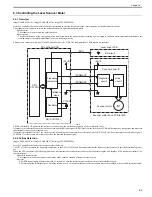
F-6-4
The DC controller PCB generates the reference clock based on the oscillation frequency of the oscillator (X1001).
It compares the intervals between the reference clock and the BD input signal (/BD1I) sent from the laser driver PCB with the frequency comparator, and monitors
the rotational counter of the scanner motor.
It controls the rotational speed of the scanner motor by sending the scanner motor acceleration signal (/SCNMACC) or the scanner motor deceleration signal (/
SCNMDEC) to the scanner motor driver based on the detected rotational speed.
6.3.2 Failure Detection
0019-5011
imageCLASS MF9170c / imageCLASS MF9150c / imageCLASS MF8450c
In the DC controller, the fault in the scanner motor is detected.
The CPU (IC1001) monitors the frequency comparator in the ASIC (IC1010) and determines whether the scanner motor rotates at its specified rotational speed or
not.
When the CPU encounters the following conditions, it determines the scanner motor failure, stops the printer engine, and displays 'E100 (optical unit failure)" on
the control panel.
- Abnormal scanner motor
The scanner motor does not enter scanner ready mode within 5 seconds of scanner motor start-up.
- BD error
- The /BDI signal cannot be detected within 1.5 seconds of once the scanner motor reached at its specified rotational speed.
- The interval of the /BDI signal goes out of the tolerance for 0.5 second continuously after the scanner motor once reached at its specified rotational speed.
ASIC (IC1010)
DC controller PCB
CPU
(IC1001)
Scanner motor drive PCB for M/C
+24VA
+24VA
BD circuit
Laser driver PCB
Scanner driver IC
Scanner motor
/SCNMACC
/SCNMDEC
X1001
/BD1I
Frequency
comparator
Reference
clock
Oscillator
Drive
circuit
Integration
circuit
M
Summary of Contents for imageCLASS MF9170c
Page 16: ...Chapter 1 Introduction ...
Page 55: ...Chapter 2 Basic Operation ...
Page 61: ...Chapter 3 Main Controller ...
Page 75: ...Chapter 4 Original Exposure System ...
Page 88: ...Chapter 5 Original Feeding System ...
Page 105: ...Chapter 6 Laser Exposure ...
Page 113: ...Chapter 7 Image Formation ...
Page 150: ...Chapter 8 Pickup and Feed System ...
Page 184: ...Chapter 9 Fixing System ...
Page 200: ...Chapter 10 External and Controls ...
Page 230: ...Chapter 11 Maintenance and Inspection ...
Page 233: ...Chapter 12 Measurement and Adjustments ...
Page 237: ...Chapter 13 Correcting Faulty Images ...
Page 260: ...Chapter 14 Error Code ...
Page 272: ...Chapter 15 Special Management Mode ...
Page 280: ...Chapter 16 Service Mode ...
Page 322: ...Chapter 17 Upgrading ...
Page 327: ...Chapter 17 17 4 3 Click Next F 17 4 4 Select a USB connected device and click Next F 17 5 ...
Page 328: ...Chapter 17 17 5 5 Click Start F 17 6 6 Click Yes F 17 7 Download will be started F 17 8 ...
Page 330: ...Chapter 18 Service Tools ...
Page 334: ...Appendix ...
Page 349: ......


