Chapter 10
10-2
10.1.2 Operation of Each Block
0020-2653
imageCLASS MF9170c / imageCLASS MF9150c / imageCLASS MF8450c
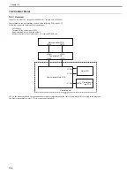
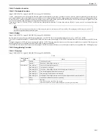
CPU (IC1001)
The CPU is a 16-bit single-chip processor with built-in ROM and RAM.
It controls the following printer operation according to the control program stored in the ROM.
- Sequence control of the printer engine
- Control of the ASIC
- Control of the fixing assembly
- Control of solenoid
- Control of sensors/switches
- Control of the fixing control circuit (relay drive)
ASIC (IC1010)
The ASIC (Application Specific IC) is an IC used in an interface such as an IC, memory, and external equipment.
It controls the following printer operation according to the command from the CPU.
- Control of the laser scanner unit
- Communication with the main controller
- Control of the high-voltage power PCB
- Control of motors
- Control of fans
- Write/Read EEPROM
- Control of the memory controller PCB
Motor Driver IC (IC401, IC802, IC803)
The motor driver IC controls each motor according to the command from the CPU or ASIC.
Reset IC (IC1007)
The reset IC mo3.3 V voltage, and resets the CPU and ASIC when the power is turned ON.
EEPROM (IC1007)
The EEPROM stores various backup data.
10.1.3 Fan/Motor Control
0020-2654
imageCLASS MF9170c / imageCLASS MF9150c / imageCLASS MF8450c
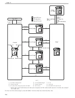
The machine uses nine motors in total for paper feeding and image formation.
T-10-1
Name
Purpose
Type
Fault detection
Motor
Fixing motor (M1)
To drive the pressure roller and delivery roller
To drive engagement/disengagement of the developing roller
To drive engagement/disengagement of the pressure roller
DC motor
Provided
Pickup motor (M4)
To drive the pickup roller of the machine
Stepping motor
Not provided
ETB motor (M5)
To drive the ETB, To drive engagement/disengagement of the transfer roller DC motor
Provided
M drum motor (M6)
To drive the developing roller, photosensitive drum, and stirring plate
DC motor
Provided
C drum motor (M7)
Y drum motor (M8)
Bk drum motor (M9)
Duplex feed motor (M10)
To drive the duplex feed roller
Stepping motor
Not provided
Reverse motor (M11)
To drive the reverse roller
Stepping motor
Not provided
Fan
Main unit fan (FM1)
To exhaust heat from the inside of the machine
DC motor
Provided
Duplex fan (FM2)
To exhaust heat from the reverse unit
DC motor
Provided
Summary of Contents for imageCLASS MF9170c
Page 16: ...Chapter 1 Introduction ...
Page 55: ...Chapter 2 Basic Operation ...
Page 61: ...Chapter 3 Main Controller ...
Page 75: ...Chapter 4 Original Exposure System ...
Page 88: ...Chapter 5 Original Feeding System ...
Page 105: ...Chapter 6 Laser Exposure ...
Page 113: ...Chapter 7 Image Formation ...
Page 150: ...Chapter 8 Pickup and Feed System ...
Page 184: ...Chapter 9 Fixing System ...
Page 200: ...Chapter 10 External and Controls ...
Page 230: ...Chapter 11 Maintenance and Inspection ...
Page 233: ...Chapter 12 Measurement and Adjustments ...
Page 237: ...Chapter 13 Correcting Faulty Images ...
Page 260: ...Chapter 14 Error Code ...
Page 272: ...Chapter 15 Special Management Mode ...
Page 280: ...Chapter 16 Service Mode ...
Page 322: ...Chapter 17 Upgrading ...
Page 327: ...Chapter 17 17 4 3 Click Next F 17 4 4 Select a USB connected device and click Next F 17 5 ...
Page 328: ...Chapter 17 17 5 5 Click Start F 17 6 6 Click Yes F 17 7 Download will be started F 17 8 ...
Page 330: ...Chapter 18 Service Tools ...
Page 334: ...Appendix ...
Page 349: ......


