Chapter 16
16-31
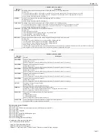
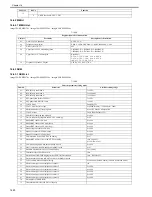
16.4.4 NCU
16.4.4.1 NCU List
0020-2023
imageCLASS MF9170c / imageCLASS MF9150c / imageCLASS MF8450c
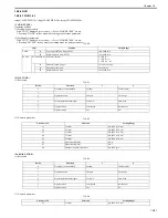
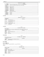
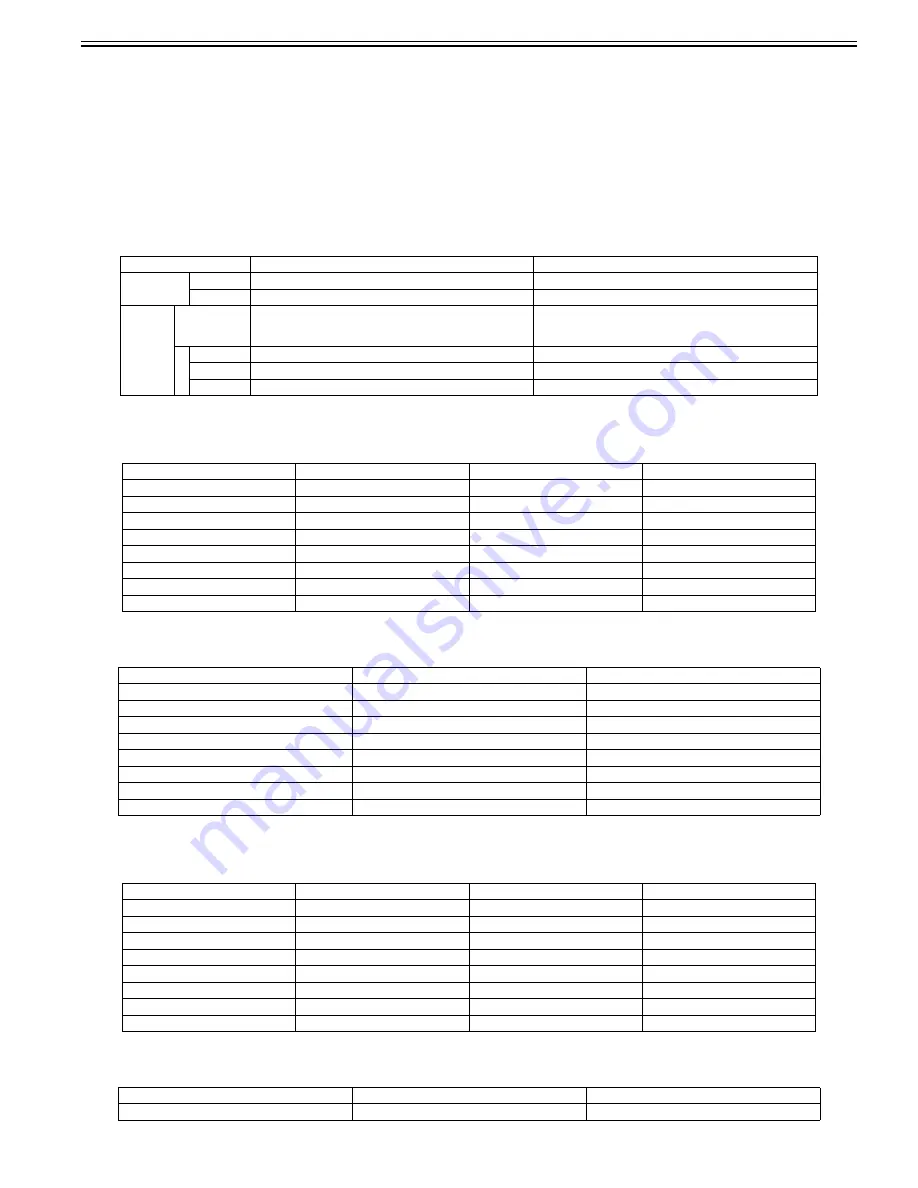
<TONE/ PULSE>
Operating Method
(1) Setting tone parameter
With "#NCU" displayed, press set key -> Press "#TONE/PULSE" set key
-> Pressing "#TONE" set key makes the setting mode for tone parameter.
(2) Setting pulse parameter
With "#NCU" displayed, press set key -> Press "#TONE/PULSE" set key.
-> Pressing "#PULSE" set key makes the setting mode for pulse parameter.
T-16-40
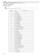
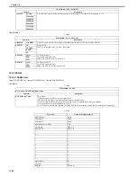
<DIAL TONE>
(1) Bit switch
T-16-41
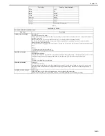
(2) Numeric parameter
T-16-42
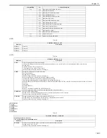
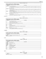
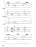
<2nd DIAL TONE>
(1) Bit switch
T-16-43
(2) Numeric parameter
T-16-44
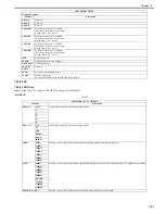
Item
Function
Setting Range
TONE
01
Tone signal delivery time (PSTN)
10 to 9999 (ms)
02
Minimum pause time (PSTN)
10 to 9999 (ms)
PULSE
PULSE FORM Pulse digit format
0 -> DP (N)
1 -> DP (N + 1)
2 -> DP (10 - N)
01
Pulse dial speed (10 pps)
5 to 300 (x 0.1 pps)
03
Pulse dial make ratio
10 to 90 (%)
04
Minimum pause time
10 to 9999 (ms)
Bit No.
Function
1
0
0
Frequency sensing method
Modem
Tonal counter
1
2
Signal frequency
Changes
No change
3
4
Screening intermittent signal
From ON
From both
5
6
Signal method
Continuous
Intermittent
7
Signal sensing
Yes
No
Parameter No.
Function
Setting Range
01
T0 timer
0 to 9999 (x 10 ms)
02
T1 timer
0 to 9999 (x 10 ms)
03
T2 timer
0 to 9999 (x 10 ms)
04
T3 timer
0 to 9999 (x 10 ms)
05
T4 timer
0 to 9999 (x 10 ms)
06
Signal sensing table
0 to 16
07
Signal sensing level
0 to 7
08
Number of signal frequencies
0 to 9999 (pce)
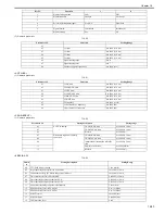
Bit No.
Function
1
0
0
Frequency sensing method
Modem
Tonal counter
1
2
Signal frequency
Changes
No change
3
4
Screening intermittent signal
From ON
From both
5
6
Signal method
Continuous
Intermittent
7
Signal sensing
Yes
No
Parameter No.
Function
Setting Range
01
T0 timer
0 to 9999 (x 10 ms)
Summary of Contents for imageCLASS MF9170c
Page 16: ...Chapter 1 Introduction ...
Page 55: ...Chapter 2 Basic Operation ...
Page 61: ...Chapter 3 Main Controller ...
Page 75: ...Chapter 4 Original Exposure System ...
Page 88: ...Chapter 5 Original Feeding System ...
Page 105: ...Chapter 6 Laser Exposure ...
Page 113: ...Chapter 7 Image Formation ...
Page 150: ...Chapter 8 Pickup and Feed System ...
Page 184: ...Chapter 9 Fixing System ...
Page 200: ...Chapter 10 External and Controls ...
Page 230: ...Chapter 11 Maintenance and Inspection ...
Page 233: ...Chapter 12 Measurement and Adjustments ...
Page 237: ...Chapter 13 Correcting Faulty Images ...
Page 260: ...Chapter 14 Error Code ...
Page 272: ...Chapter 15 Special Management Mode ...
Page 280: ...Chapter 16 Service Mode ...
Page 322: ...Chapter 17 Upgrading ...
Page 327: ...Chapter 17 17 4 3 Click Next F 17 4 4 Select a USB connected device and click Next F 17 5 ...
Page 328: ...Chapter 17 17 5 5 Click Start F 17 6 6 Click Yes F 17 7 Download will be started F 17 8 ...
Page 330: ...Chapter 18 Service Tools ...
Page 334: ...Appendix ...
Page 349: ......

