Chapter 7
7-31
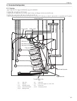
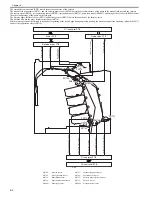
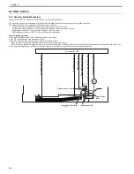
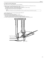
F-7-64
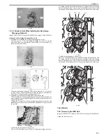
7.5.3.3 Points to Note When Installing the Developing
Disengage Solenoid
0019-6131
imageCLASS MF9170c / imageCLASS MF9150c / imageCLASS MF8450c
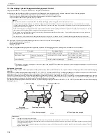
Alignment of Developing Disengage Drive Unit
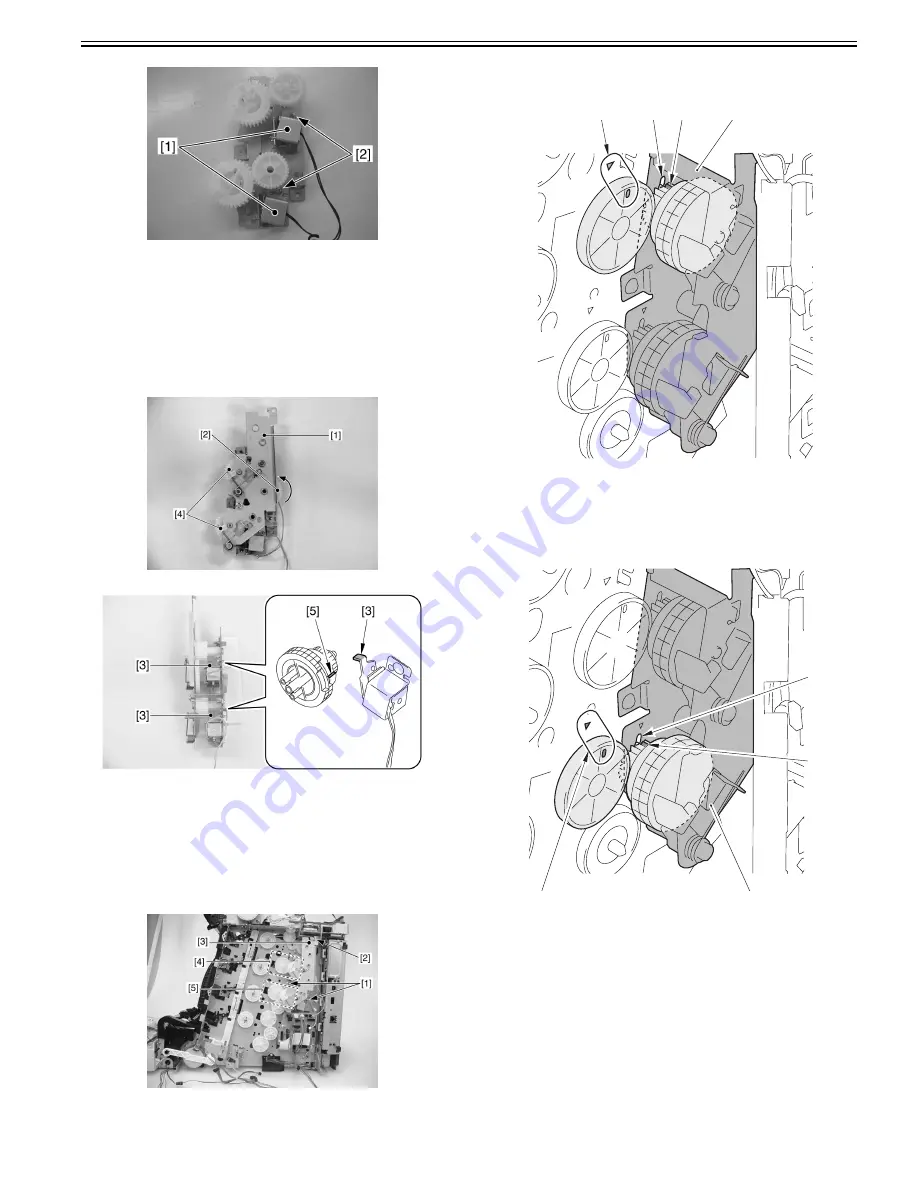
1. Alignment in assembling the developing disengage drive unit
Turn the gear [2] of the developing disengage drive unit [1] in the
direction of the arrow, and align the solenoid claw [3] with the cutoff [5]
in the gear (home position).
F-7-65
F-7-66
When the developing disengage drive unit is properly set to its home
position, the gear [4] does not rotate if turning the gear [2], and there will
be no sense of resistance when rotating the gear [2].
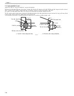
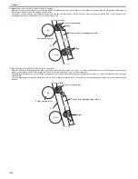
2. Alignment in installing the developing disengage drive unit
When installing the developing disengage drive unit while the main drive
unit is removed, the corresponding gears of the host machine need to be
aligned (interlocked).
Tighten the 2 screws [1] to the developing disengage drive unit [3] and
tighten the screw [2] halfway to confirm the alignment of the gear [4] and
the gear [5].
F-7-67
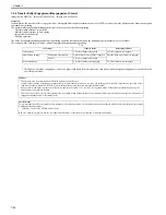
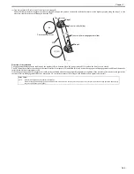
Confirming the alignment of the gear [4]
There is a small-toothed gear [3] in the developing disengage drive unit
[1]. Make sure that the small-toothed gear is aligned with the elongate
hole [2] (home position). Also, as shown in the figure [4], make sure that
the triangle and the elongate hole of the gear lie right next to each other.
F-7-68
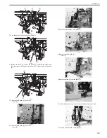
Confirming the alignment of the gear [5]
There is a small-toothed gear [3] in the developing disengage drive unit
[1]. Make sure that the small-toothed gear is aligned with the elongate
hole [2] (home position). Also, as shown in the figure [4], make sure that
the triangle and the elongate hole of the gear lie right next to each other.
F-7-69
7.5.4 ETB Unit
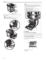
7.5.4.1 Removing the ETB Unit
0019-5793
imageCLASS MF9170c / imageCLASS MF9150c / imageCLASS MF8450c
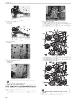
1) Open the front cover [1].
[1]
[2]
[3]
[4]
[1]
[3]
[2]
[4]
Summary of Contents for imageCLASS MF9170c
Page 16: ...Chapter 1 Introduction ...
Page 55: ...Chapter 2 Basic Operation ...
Page 61: ...Chapter 3 Main Controller ...
Page 75: ...Chapter 4 Original Exposure System ...
Page 88: ...Chapter 5 Original Feeding System ...
Page 105: ...Chapter 6 Laser Exposure ...
Page 113: ...Chapter 7 Image Formation ...
Page 150: ...Chapter 8 Pickup and Feed System ...
Page 184: ...Chapter 9 Fixing System ...
Page 200: ...Chapter 10 External and Controls ...
Page 230: ...Chapter 11 Maintenance and Inspection ...
Page 233: ...Chapter 12 Measurement and Adjustments ...
Page 237: ...Chapter 13 Correcting Faulty Images ...
Page 260: ...Chapter 14 Error Code ...
Page 272: ...Chapter 15 Special Management Mode ...
Page 280: ...Chapter 16 Service Mode ...
Page 322: ...Chapter 17 Upgrading ...
Page 327: ...Chapter 17 17 4 3 Click Next F 17 4 4 Select a USB connected device and click Next F 17 5 ...
Page 328: ...Chapter 17 17 5 5 Click Start F 17 6 6 Click Yes F 17 7 Download will be started F 17 8 ...
Page 330: ...Chapter 18 Service Tools ...
Page 334: ...Appendix ...
Page 349: ......


