Chapter 8
8-9
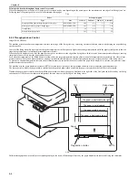
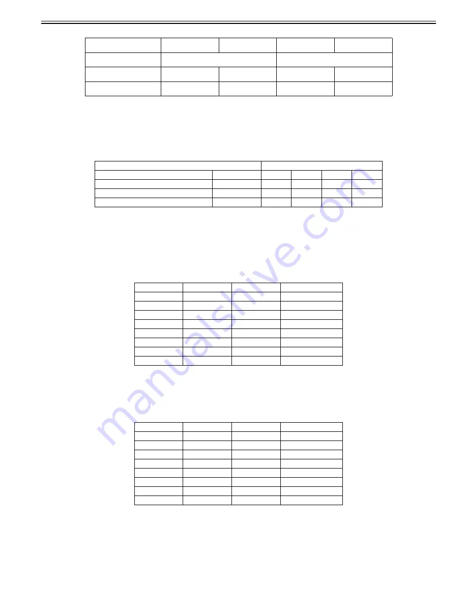
T-8-4
*1: For the universal-size paper or the paper of which width is smaller than A4-size, an interval between sheets is changed step by step according to the
temperature detected by the fixing sub thermistor.
*2: Although throughput-down control is not performed, a restriction is applied to the power supplied to the fixing heater.
Print speed when the throughput down control is executed
When the throughput down control is ON, print speed is switched step by step depending on the paper type or the temperature on the edge of the fixing sleeve etc.
Following shows the print speed list in case of the minimum throughput.
T-8-5
*: Throughput down is executed in the same manner in case of plain paper H, thick paper 1, thick paper 2 and rough paper.
8.2.6 Feeding Speed Control
0019-5031
imageCLASS MF9170c / imageCLASS MF9150c
The machine switches the paper feeding speed depending on the type of paper fed in order to prevent a fixing failure.
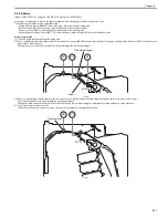
The DC controller switches the paper feeding speed over 4 settings (1/1 speed, 4/5 speed, 1/2 speed, 2/5 speed) depending on the paper type specified by the main
controller.
T-8-6
8.2.7 Feeding Speed Control
0020-9284
imageCLASS MF8450c
The machine switches the paper feeding speed depending on the type of paper fed in order to prevent a fixing failure.
The DC controller switches the paper feeding speed over 3 settings (1/1 speed, 5/8 speed, 1/2 speed) depending on the paper type specified by the main controller.
T-8-7
8.2.8 Warp Control
0019-5032
imageCLASS MF9170c / imageCLASS MF9150c / imageCLASS MF8450c
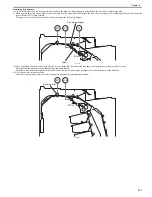
To prevent an image failure, it is necessary to keep the paper warped at an appropriate level between the fixing assembly and the ETB.
When the paper transport speed of the pressure roller is slower than that of the ETB, the paper warp increases, and an image defect or paper crease occurs. Con-
versely, the speed is faster than that of the ETB, the paper is pulled by the pressure roller, and a color displacement occurs in the sub-scanning direction.
The machine controls the rotational speed of the fixing motor (M1), which drives the pressure roller, to keep an appropriate level of paper warp.
Paper displacement
The paper is displaced
to the left side
The paper width is
smaller *1
The paper is not
displaced
The paper is displaced
to the right side
Paper displacement detection
sensor (SR714)
No paper detection is performed
Paper detection is performed
Fixing sub thermistor (TH2)
Lower than the
specified temperature
Higher than the
specified temperature
Lower than the
specified temperature
Higher than the
specified temperature
Throughput-down control
Instantly executed (the
lowest value)
Executed step by step
No throughput-down
control performed
No throughput-down
control performed *2
Paper
Print speed (ppm)
Type
Size
1st level
2nd level
3rd level
Last level
Plain paper/Recycled paper/Color paper *
B5R/A5R/EXECR
16.1
4.4
3.4
2.76
Transparency
-
3.6
2.4
-
1.8
Postcard/Return postal card
-
10.1
3.8
3
2.5
Paper
Grammage
Paper type
Paper feeding speed
Plain paper
60 to 105 g/m2
Plain paper
1/1
Thick paper
105 to 120 g/m2
Thick paper 1
4/5
Thick paper
121 to 176 g/m2
Thick paper 2
4/5
Postcard
up to 190 g/m2
Postcard
1/2
Rough paper
-
Rough
2/5
Label
-
Label
4/5
Envelope
-
Envelope
4/5
Transparency
-
Transparency
2/5
Paper
Grammage
Paper type
Paper feeding speed
Plain paper
60 to 105 g/m2
Plain paper
1/1
Thick paper
105 to 120 g/m2
Thick paper 1
1/1
Thick paper
121 to 176 g/m2
Thick paper 2
1/1
Postcard
up to 190 g/m2
Postcard
5/8
Rough paper
-
Rough
1/2
Label
-
Label
1/1
Envelope
-
Envelope
1/1
Transparency
-
Transparency
1/2
Summary of Contents for imageCLASS MF9170c
Page 16: ...Chapter 1 Introduction ...
Page 55: ...Chapter 2 Basic Operation ...
Page 61: ...Chapter 3 Main Controller ...
Page 75: ...Chapter 4 Original Exposure System ...
Page 88: ...Chapter 5 Original Feeding System ...
Page 105: ...Chapter 6 Laser Exposure ...
Page 113: ...Chapter 7 Image Formation ...
Page 150: ...Chapter 8 Pickup and Feed System ...
Page 184: ...Chapter 9 Fixing System ...
Page 200: ...Chapter 10 External and Controls ...
Page 230: ...Chapter 11 Maintenance and Inspection ...
Page 233: ...Chapter 12 Measurement and Adjustments ...
Page 237: ...Chapter 13 Correcting Faulty Images ...
Page 260: ...Chapter 14 Error Code ...
Page 272: ...Chapter 15 Special Management Mode ...
Page 280: ...Chapter 16 Service Mode ...
Page 322: ...Chapter 17 Upgrading ...
Page 327: ...Chapter 17 17 4 3 Click Next F 17 4 4 Select a USB connected device and click Next F 17 5 ...
Page 328: ...Chapter 17 17 5 5 Click Start F 17 6 6 Click Yes F 17 7 Download will be started F 17 8 ...
Page 330: ...Chapter 18 Service Tools ...
Page 334: ...Appendix ...
Page 349: ......

