S
ERVICE
P
ROCEDURES
41
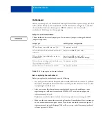
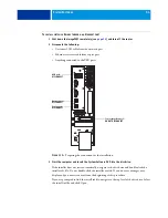
Service board
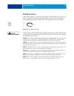
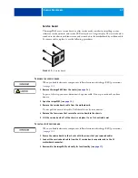
The imagePASS uses a service board to offer service mode switches for installing system
software over the network, and service LEDs arrayed as a 2-digit display. The service board is
attached to the chassis with four screws and is attached to the motherboard by a ribbon cable.
To remove and/or replace it, use the following procedures.
F
IGURE
17:
Service board
T
O
REMOVE
THE
SERVICE
BOARD
When you handle electronic components, follow electrostatic discharge (ESD) precautions
(see
1 Remove the imagePASS from the copier (see
As part of this step, you must disconnect the power cable. Do not proceed until you have
done so.
2 Open the imagePASS (see
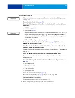
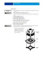
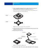
3 Remove the service board cable from the motherboard.
Do not pull the wires of the cable. Pull the cable out by its connector.
4 Remove the four screws that secure the service board to the chassis.
5 Lift the service board off of the chassis and place it on a flat, antistatic mat.
T
O
INSTALL
THE
S
ERVICE
BOARD
When you handle electronic components, follow electrostatic discharge (ESD) precautions
(see
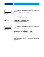
1 Secure the service board to the chassis with the screws that you removed earlier.
2 Connect the service board cable from the J1 service board connector and to the J5
motherboard connector.
3 Reassemble the imagePASS and verify its functionality (see


