8
8
8-129
8-129
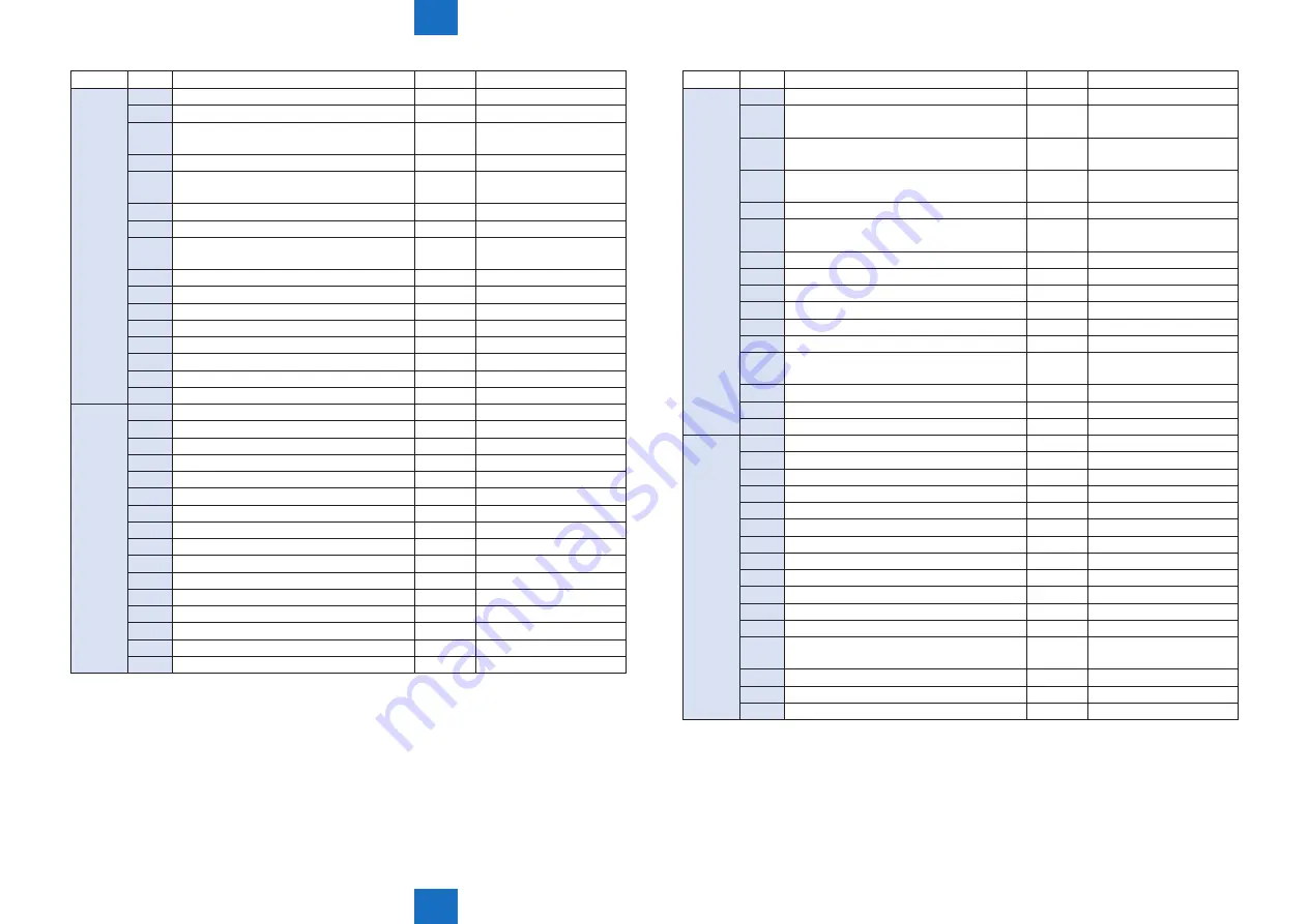
Service Mode > COPIER > I / O > Perfect Binder (SORTER > P076 to P134)
Service Mode > COPIER > I / O > Perfect Binder (SORTER > P076 to P134)
Address
bit
Name
Symbol
Remarks
P086
15
+24V2 control
-
0: Stacking job
14
+24V1 control
-
0: Operating job
13
+5V1 control
-
0: Sensor power supply
ON
12
Power supply 2 remote
-
1: Power ON
11
THROUGH
-
0: Cut power except threw
pass
10
STANDBY
-
0: Power cut (almost all)
9
-
-
8
Power supply cooling fan
FM1,
FM2, FM3
1: ON
7
Service PCB DIP switch 8
-
0: ON
6
Service PCB DIP switch 7
-
0: ON
5
Service PCB DIP switch 6
-
0: ON
4
Service PCB DIP switch 5
-
0: ON
3
Service PCB DIP switch 4
-
0: ON
2
Service PCB DIP switch 3
-
0: ON
1
Service PCB DIP switch 2
-
0: ON
0
Service PCB DIP switch 1
-
0: ON
P087
15
Service PCB LED 3
-
0: ON
14
Service PCB LED 2
-
0: ON
13
Service PCB LED 1
-
0: ON
12
-
-
11
Low power LED
-
1: ON
10
Front cover lock LED
-
1: ON
9
-
-
-
8
-
-
-
7
Service PCB DIP switch upper 4
-
0: ON
6
Service PCB DIP switch upper 3
-
0: ON
5
Service PCB DIP switch upper 2
-
0: ON
4
Service PCB DIP switch upper 1
-
0: ON
3
Power save key
-
0: ON
2
Service PCB push switch 3
-
0: ON
1
Service PCB push switch 2
-
0: ON
0
Service PCB push switch 1
-
0: ON
Address
bit
Name
Symbol
Remarks
P088
15
5V1 Monitoring
-
1: Normal
14
24V2 Monitoring
-
0: Normal (+24V2 control
"0")
13
24V1 Monitoring
-
0: Normal (+24V1control
"0")
12
Glue case full sensor AD
S32T,
S32L
-
11
-
-
-
10
Glue case empty sensor AD
S31T,
S31L
-
9
Insertion connect signal
-
0: Connect
8
-
-
-
7
-
-
-
6
-
-
-
5
-
-
-
4
-
-
-
3
Power supply cooling fan (left) lock
detection
FM3
1: Lock
2
Front cover lock release sensor
S30
0: Lock
1
-
-
-
0
Stacking tray empty sensor
S8
1: Paper
P089
15
Sub gripper lift motor B*-phase
M17
-
14
Sub gripper lift motor A*-phase
M17
-
13
Sub gripper lift motor B-phase
M17
-
12
Sub gripper lift motor A-phase
M17
-
11
Stack delivery roller motor B*-phase
M27
-
10
Stack delivery roller motor A*-phase
M27
-
9
Stack delivery roller motor B-phase
M27
-
8
Stack delivery roller motor A-phase
M27
-
7
Registration unit home position sensor
S70
1: Home position
6
Glue roller motor clock
M25
-
5
Size shift home position sensor
S38
1: Home position
4
Glue vat shift motor clock
M32
-
3
Stack delivery sensor
S64T,
S64L
1: Paper or wait
2
Not use
-
-
1
Sub gripper home position sensor
S37
1: Home position
0
Main gripper lift motor clock
M22
-
Summary of Contents for imagePRESS 1110
Page 242: ...3 3 Periodical Service Periodical Service Periodical service item ...
Page 655: ...5 5 Adjustment Adjustment Overview When replacing parts Major adjustment ...
Page 944: ...8 8 Service Mode Service Mode Overview COPIER FEEDER SORTER BOARD Situation Mode ...
Page 1555: ... Service Tools General Circuit Diagram General Timing Chart Operator Maintenance Appendix ...


