8
8
8-176
8-176
Service Mode > COPIER > ADJUST (Adjustment Mode) > DENS
Service Mode > COPIER > ADJUST (Adjustment Mode) > DENS
■
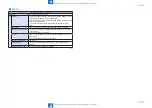
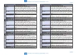
DEVELOP
COPIER> ADJUST> DEVELOP
DE-NO-DC
Set develp DCbias beside image formation
Lv.1 Details
To set the developing DC bias value besides the image formation.
Caution
• Do not use this at normal service.
• This is effective when the following is set to “0” (potential control is
OFF):COPIER> OPTION> FNC-SW> PO-CNT.
Display/adj/set range
0 to 600
Unit
V
Related service mode
COPIER> OPTION> FNC-SW> PO-CNT
VPP-WB
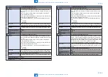
Set of white band mode develop AC bias
Lv.2 Details
To set the developing AC bias Vpp at white band toner ejection.
As the smaller value is set, the white band is more effective while the
pre-transfer charging wire tends to get dirt.
When the developing bias leakage occurs, set the greater value and
when the reverse foggy occurs, set the smaller value.
Use case
When the leakage from the developing roller (developing bias leak)
occurs in highland low-density environment.
Adj/set/operate method Enter the setting value and press OK key.
Display/adj/set range
0 to 2
0: 1.5 kV, 1: 1.3 kV, 2: 0 V
Default value
2
Related service mode
COPIER> ADJUST> MISC> TBSIS-WB, MAXT-WB
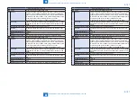
FRQ-DEV
Set of developing bias frequency
Lv.2 Details
Set the frequency of the developing bias.
In the low pressure environment, decrease the value if bias leak
occurs, increase the value if fogging image occurs.
Use case
When image bias leak occurs in the low pressure environment
Adj/set/operate method Enter the setting value (switch negative/positive by -/+ key) and
press OK key.
Display/adj/set range
-2 to 1
-2: 2.0 kHz, -1: 2.5 kHz, 0: 2.7 kHz, 1: 3.0 kHz
Default value
0
BIAS-WB
White band mode developing bias setting
Lv.2 Details
Set the developing AC/DC bias during white band toner ejection.
The combination of AC element and DC element of the developing
bias differs for each set value. Select the appropriate combination for
set value accordingly.
Use case
When fogging image occurs
Adj/set/operate method Enter the setting value and press OK key.
Display/adj/set range
0 to 3
0 : white band bias 0, 1: white band bias 1, 2 : white band bias 2, 3 :
white band bias 3
Default value
0
Related service mode
COPIER> ADJUST> MISC> TBSIS-WB
T-8-36
■
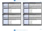
DENS
COPIER> ADJUST> DENS
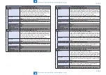
DENS-ADJ
Density correction of copy image
Lv.1 Details
To correct the density of copy image by changing the F value table.
When the DC controller PCB is replaced or RAM is cleared, enter the
value of service label.
As the value is increased, white gap is reduced and as the value is
decreased, fogging is reduced.
Use case
When fogging or white gap on the high-density area appears on the
copy image.
Adj/set/operate method Enter the setting value and press OK key.
Caution
Density of the printer output image cannot be corrected.
Display/adj/set range
1 to 9
Appropriate target value 4 to 6
Default value
5
Supplement/memo
F value table: this indicates the relation between the original density
and the image density.
P-OFFSET
Dspl/adj of patch detection offset value
Lv.1 Details
To display/adjust the patch detection offset value that is used at the
patch detection sensor.
Use case
When the solid density is out of the specified range even though
there is no issue on the high-voltage or the developing assembly.
When the solid density is out of the specified range after the
replacement of sensor or extended use.
Adj/set/operate method 1) Check that the density change is due to patch detection (high-
voltage etc.)
2) Enter the setting value and press OK key.
3) Execute the D-max control manually.
4) Check the density of solid area of 17 gradations.
Display/adj/set range
-128 to 128
Appropriate target value 0 to 64
Default value
36
Related service mode
COPIER> FUNCTION> MISC-P> P-LPADJ, DMAX-N
Summary of Contents for imagePRESS 1110
Page 242: ...3 3 Periodical Service Periodical Service Periodical service item ...
Page 655: ...5 5 Adjustment Adjustment Overview When replacing parts Major adjustment ...
Page 944: ...8 8 Service Mode Service Mode Overview COPIER FEEDER SORTER BOARD Situation Mode ...
Page 1555: ... Service Tools General Circuit Diagram General Timing Chart Operator Maintenance Appendix ...


