8
8
8-470
8-470
Service Mode > Situation Mode > Parts Replacement
Service Mode > Situation Mode > Parts Replacement
Title
Active Registration Unit
Explaination 1) Execute light intensity auto adjustment in service mode.
(Level 2) COPIER > FUNCTION > SENS-ADJ > OP-SENS (auto adjustment of the
Scanner Sensor)
2) Execute CIS LED light intensity auto adjustment in service mode.
(Level 1) COPIER > FUNCTION > SENS-ADJ > CIS (CIS light intensity adjustment)
3) Execute skew adjustment.
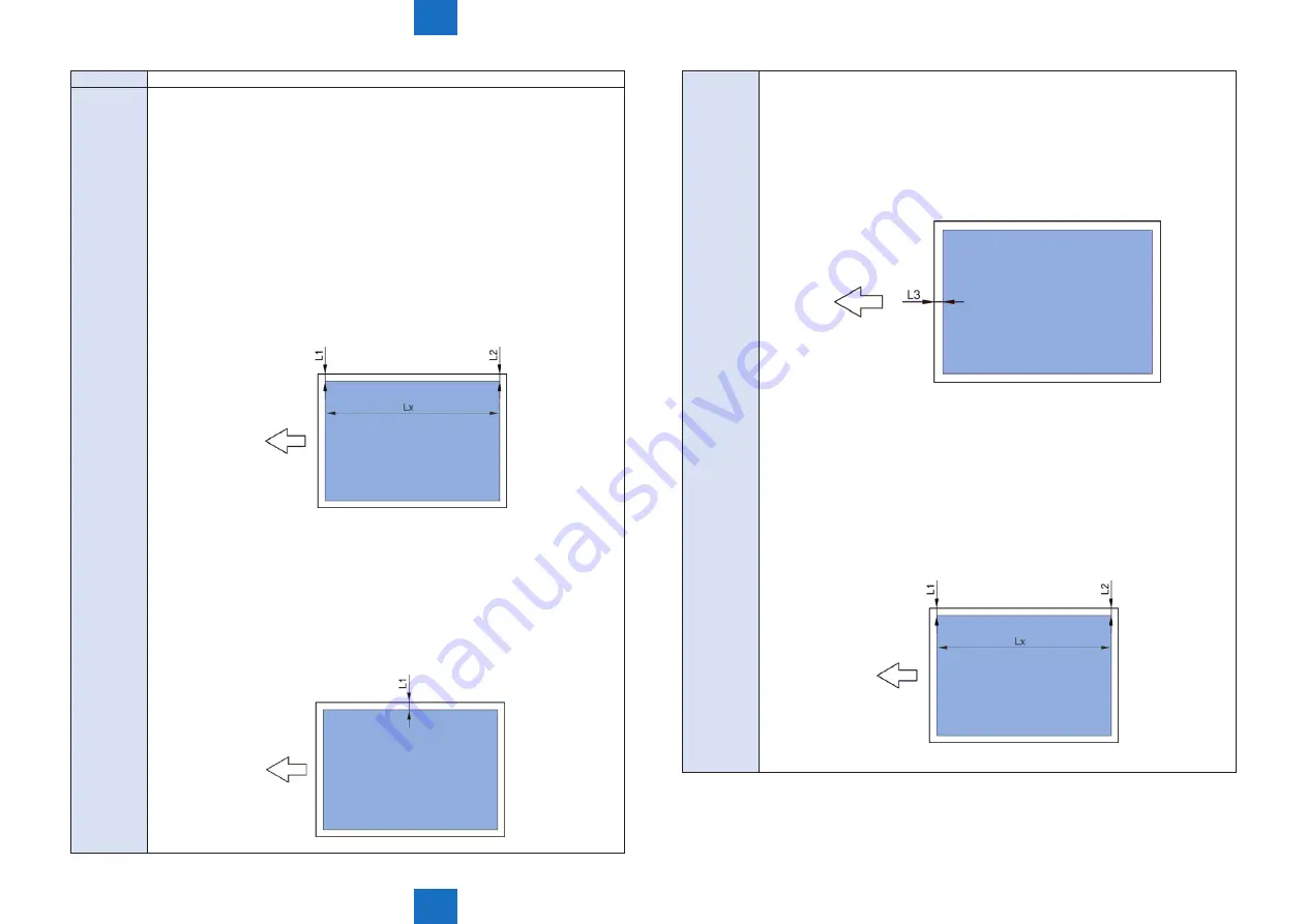
3-1) Using a loupe (CK-0056), measure the margins L1 and L2 at the right edge of
a test print in increments of 0.05mm.
3-2) Obtain the skew adjustment value R from the following formula.
R = ((L2 - L1) / Lx) x 15200 (Round off the value to the nearest whole number.)
If the absolute value of the skew adjustment value R is 0.2 or larger
(R </= -0.2, 0.2 </= R), perform step 3.
3-3) Enter the skew adjustment value R in the following service mode.
(Level 1) COPIER > ADJUST > FEED-ADJ > REG-SKEW
Adjustment range: -500 to 500
Unit: 0.01mm
4) Execute right edge registration adjustment.
4-1) Measure the right edge margin L1 [in increments of 0.1mm] of a test print.
4-2) In the following service mode, adjust the right edge margin L1 to be within the
range of standard value 2.5 +/- 0.5mm.
(Level 1) COPIER > ADJUST > FEED-ADJ > REG-R
Adjustment range: -50 to 50
Unit: 0.1mm
If L1 > 2.5mm, increase the adjustment value.
If L1 < 2.5mm, decrease the adjustment value.
Explaination 5) Execute leading edge registration adjustment.
5-1) Measure the leading edge margin L3 [in increments of 0.1mm] of a test print.
5-2) In the following service mode, adjust the leading edge margin L3 to be within
the range of standard value 2.5 +/- 0.5mm.
(Level 1) COPIER > ADJUST > FEED-ADJ > REG-TOP
Adjustment range: -50 to 50
Unit: 0.1mm
If L3 > 2.5mm, decrease the adjustment value.
If L3 < 2.5mm, increase the adjustment value.
6) Execute skew adjustment.
6-1) Using a loupe (CK-0056), measure the margins L1 and L2 at the right edge of
a test print in increments of 0.05mm.
6-2) Obtain the skew adjustment value R from the following formula.
R = ((L2 - L1) / Lx) x 15200 (Round off the value to the nearest whole number.)
If the absolute value of the skew adjustment value R is 0.2 or larger
(R </= -0.2, 0.2 </= R), perform step 3.
6-3) Enter the skew adjustment value R in the following service mode.
(Level 1) COPIER > ADJUST > FEED-ADJ > REG-SKEW
Adjustment range: -500 to 500
Unit: 0.01mm
Summary of Contents for imagePRESS 1110
Page 242: ...3 3 Periodical Service Periodical Service Periodical service item ...
Page 655: ...5 5 Adjustment Adjustment Overview When replacing parts Major adjustment ...
Page 944: ...8 8 Service Mode Service Mode Overview COPIER FEEDER SORTER BOARD Situation Mode ...
Page 1555: ... Service Tools General Circuit Diagram General Timing Chart Operator Maintenance Appendix ...


