7
7
7-155
7-155
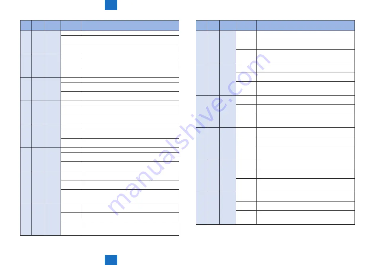
Error Code > Error Code > Error Code Details
Error Code > Error Code > Error Code Details
Code
Detail
Code
Location
Item
Description
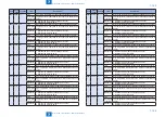
E864 0001 13
Title
Error in path motor driver PCB (PCB5)_24V
Description
of detection
5V of path motor driver PCB (PCB5) is OFF.
Measures 1. Replace the Path motor driver PCB (PCB5).
2. Replace the DC relay PCB.
E864 0001 21
Title
Error in path motor driver PCB (PCB5)_24V
Description
of detection
5V of path motor driver PCB (PCB5) is OFF.
Measures 1. Replace the Path motor driver PCB (PCB5).
2. Replace the DC relay PCB.
E864 0002 11
Title
Error in path motor driver PCB (PCB5)_5V
Description
of detection
5V of path motor driver PCB (PCB5) is OFF.
Measures 1. Replace the Path motor driver PCB (PCB5).
2. Replace the DC relay PCB.
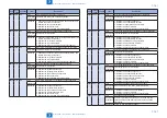
E864 0002 12
Title
Error in path motor driver PCB (PCB5)_5V
Description
of detection
5V of path motor driver PCB (PCB5) is OFF.
Measures 1. Replace the Path motor driver PCB (PCB5).
2. Replace the DC relay PCB.
E864 0002 13
Title
Error in path motor driver PCB (PCB5)_5V
Description
of detection
5V of path motor driver PCB (PCB5) is OFF.
Measures 1. Replace the Path motor driver PCB (PCB5).
2. Replace the DC relay PCB.
E864 0002 21
Title
Error in path motor driver PCB (PCB5)_5V
Description
of detection
5V of path motor driver PCB (PCB5) is OFF.
Measures 1. Replace the Path motor driver PCB (PCB5).
2. Replace the DC relay PCB.
E864 0003 11
Title
Contact failure on connector (J3002) of path motor driver
PCB (PCB5)
Description
of detection
When contact failure on J3002 connector is detected.
Measures 1. Check the connector (J3002).
2. Replace the path motor driver PCB.
3. Replace the POD deck controller PCB.
E864 0003 12
Title
Contact failure on connector (J3002) of path motor driver
PCB (PCB5)
Description
of detection
When contact failure on J3002 connector is detected.
Measures 1. Check the connector (J3002).
2. Replace the path motor driver PCB.
3. Replace the POD deck controller PCB.
Code
Detail
Code
Location
Item
Description
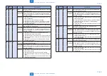
E864 0003 13
Title
Contact failure on connector (J3002) of path motor driver
PCB (PCB5)
Description
of detection
When contact failure on J3002 connector is detected.
Measures 1. Check the connector (J3002).
2. Replace the path motor driver PCB.
3. Replace the POD deck controller PCB.
E864 0003 21
Title
Contact failure on connector (J3002) of path motor driver
PCB (PCB5)
Description
of detection
When contact failure on J3002 connector is detected.
Measures 1. Check the connector (J3002).
2. Replace the path motor driver PCB.
3. Replace the POD deck controller PCB.
E864 0004 11
Title
Contact failure on connector (J3003) of path motor driver
PCB (PCB5)
Description
of detection
When contact failure on J3003 connector is detected.
Measures 1. Check the connector (J3003).
2. Replace the path motor driver PCB.
3. Replace the POD deck controller PCB.
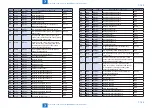
E864 0004 12
Title
Contact failure on connector (J3003) of path motor driver
PCB (PCB5)
Description
of detection
When contact failure on J3003 connector is detected.
Measures 1. Check the connector (J3003).
2. Replace the path motor driver PCB.
3. Replace the POD deck controller PCB.
E864 0004 13
Title
Contact failure on connector (J3003) of path motor driver
PCB (PCB5)
Description
of detection
When contact failure on J3003 connector is detected.
Measures 1. Check the connector (J3003).
2. Replace the path motor driver PCB.
3. Replace the POD deck controller PCB.
E864 0004 21
Title
Contact failure on connector (J3003) of path motor driver
PCB (PCB5)
Description
of detection
When contact failure on J3003 connector is detected.
Measures 1. Check the connector (J3003).
2. Replace the path motor driver PCB.
3. Replace the POD deck controller PCB.
Summary of Contents for imagePRESS 1110
Page 242: ...3 3 Periodical Service Periodical Service Periodical service item ...
Page 655: ...5 5 Adjustment Adjustment Overview When replacing parts Major adjustment ...
Page 944: ...8 8 Service Mode Service Mode Overview COPIER FEEDER SORTER BOARD Situation Mode ...
Page 1555: ... Service Tools General Circuit Diagram General Timing Chart Operator Maintenance Appendix ...


