8
8
8-22
8-22
Service Mode > COPIER > DISPLAY (Status Display Mode) > ACC-STS
Service Mode > COPIER > DISPLAY (Status Display Mode) > ACC-STS
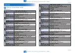
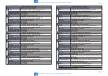
COPIER> DISPLAY> ACC-STS
SEND
Dspl of existance of SEND support PCB
Lv.1 Details
To display if there is PCB to support SEND function.
SEND function can be used only when the PCB is mounted.
Use case
When checking connection between the host machine and the PCB
that supports SEND function.
Adj/set/operate method N/A (display only)
Display/adjust/set range 0 to 1
0: (PCB is) not mounted, 1: (PCB is ) mounted
TRIM-CN
Dspl of trimmer connection status
Lv.1 Details
Displaying connecting status of the trimmer.
Use case
When checking the conection between the host machine and the
trimmer.
Adj/set/operate method N/A (display only)
Display/adjust/set range 0 to 1
0: no connection, 1: connected (active)
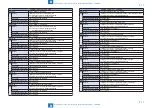
PDL-FNC1
Dspl of active PDL function 1
Lv.1 Details
Displaying active/invalid state of PDL function in bit row.
Invalid if the corresponding bit (for each function) is 0, active if the
corresponding bit is 1
Use case
When displaying the available PDL on the machine.
Adj/set/operate method N/A (display only)
Display/adjust/set range 0000 0000 0000 0000 to 1111 1111 1111 1111
0: Invalid, 1: Active
bit31: BDL
bit30: PS
bit29: PCL
bit28: PDF
bit27: LIPS(LIPS/LX emulation)
bit26: N201(LIPS/LX emulation)
bit25: I5577(LIPS/LX emulation)
bit24: ESC/P (LIPS/LX emulation)
bit23: HPGL(LIPS/LX emulation)
bit22: HPCL2(LIPS/LX emulation)
PDL-FNC2
Dspl of active PDL function 2
Lv.1 Details
Displaying active/invalid state of PDL function in bit row.
Invalid if the corresponding bit (for each function) is 0, active if the
corresponding bit is 1
Use case
When displaying the available PDL on the machine.
Adj/set/operate method N/A (display only)
Display/adjust/set range 0000 0000 0000 0000 to 1111 1111 1111 1111
0: Invalid, 1: Active
b15 to b0: Reserve (to be used when PDL is newly added)
HDD
Display of HDD model name
Lv.1 Details
Displaying the model name of HDD.
Use case
When checking model name of HDD used with the host machine.
Adj/set/operate method N/A (display only)
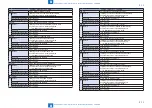
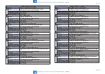
COPIER> DISPLAY> ACC-STS
PCI1
Display of PCI1 connected PCB
Lv.1 Details
Displaying name of the PCB that connects to PCI1.
Check that the PCB name is properly displayed.
Use case
When checking name of the PCB that connects to PCI1.
Adj/set/operate method N/A (display only)
Display/adjust/set range -: No connecting PCB
Voice Board: Voice PCB
3DES Board: Encryption PCB
1Gbit-Board: Giga Ethernet PCB
PCI2
Display of PCI2 connected PCB
Lv.1 Details
Displaying name of the OCB that connects to PCI2.
Check that the PCB name is properly displayed.
Use case
When checking name of the PCB that connects to PCI2.
Adj/set/operate method N/A (display only)
Display/adjust/set range -: No connecting PCB
iSLOT: iSLOT wireless LAN PCB
Voice Board: Voice PCB
Voice Board R: Voice recognition PCB (hidden display with this
equipment)
3DES Board: Encryption PCB
1Gbit-Board: Giga Ethernet PCB
PCI3
Display of PCI3 connected PCB
Lv.1 Details
Displaying name of the PCB that connects to PCI3.
Check that the PCB name is properly displayed.
Use case
When checking name of the PCB that connects to PCI3.
Adj/set/operate method N/A (display only)
Display/adjust/set range -: No connecting PCB
iSLOT: iSLOT wireless LAN PCB
Voice Board: Voice PCB
Voice Board R: Voice recognition PCB (hidden display with this
equipment)
3DES Board: Encryption PCB
1Gbit-Board: Giga Ethernet PCB
IA-RAM
Dspl of memory(IA) capacity of MNCON PCB
Lv.1 Details
Displaying memory (IA) capacity on the main controller PCB.
Use case
When checking memory capacity on the main controller PCB.
Adj/set/operate method N/A (display only)
Unit
MB
Default value
512
T-8-5
Summary of Contents for imagePRESS 1110
Page 242: ...3 3 Periodical Service Periodical Service Periodical service item ...
Page 655: ...5 5 Adjustment Adjustment Overview When replacing parts Major adjustment ...
Page 944: ...8 8 Service Mode Service Mode Overview COPIER FEEDER SORTER BOARD Situation Mode ...
Page 1555: ... Service Tools General Circuit Diagram General Timing Chart Operator Maintenance Appendix ...

