Chapter 16
16-86
13. CST-ADJ
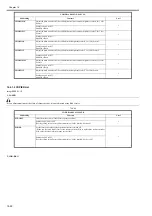
T-16-84
ADJ-REFE
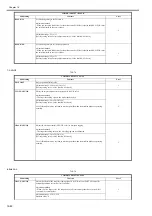
Adjust the horizontal registration for double sided copy. (for factory use)
Adjustment method
When you increase the value, the second side image moves to the rear side. (When you increase
the value by 1, the image moves by 0.1mm.)
1
Adjustment range: -100 to 100
[Factory setting value / Value after RAM clear: 0]
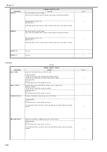
BLK-SML2
Adjust the right and left margins on the second side of a small-size sheet.
When you increase the value, the left and right margins on the second side become longer. (When
you increase the value by 1, the margins increase by 0.1mm.)
1
Adjustment range: -50 to 50 (Unit: 0.1mm)
[Factory setting value / Value after RAM clear: -15]
RVS-FD1
Adjust the reverse point.
2
Adjustment range: -10 to +10 (Unit: 1mm)
[Factory setting value / Value after RAM clear: 0]
RVS-DUP
Adjust the reverse point for double sided copy.
2
Adjustment range: -10 to 10
[Factory setting value / Value after RAM clear: 0]
LOOP-T2
Adjust the registration loop volume when feeding thick paper.
Adjustment method
When you decrease the setting value (loop volume of the registration roller), a noise is reduced.
However, when you decrease the loop volume excessively, the margin size may change or it may
cause a skew.
2
Adjustment range
-10 to +10 (mm)
[Factory setting value / Value after RAM clear: 0]
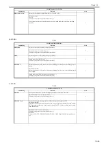
REG-SPD
Make a fine adjustment of the registration motor speed at constant speed.
Change the registration speed at constant speed in the range of + or - 10 scales against the default
value.
2
Setting range
-10 to 10
Standard value
0
REG-SPD2
Make a fine adjustment of the registration motor speed at 1/3 speed.
Change the registration speed at 1/3 speed in the range of + or - 10 scales against the default value.
2
Setting range
-10 to 10
Standard value
0
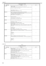
COPIER>ADJUST>CST-ADJ
Subheading Contents
Level
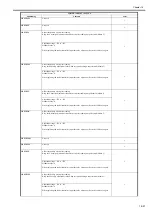
MF-A4R
Enter the basic value of the paper width for the manual feed tray. (A4R)
Adjustment method
- When you executed 'RAM clear' for the DC controller PCB or replaced the DC controller PCB,
enter the value indicated in the service label.
- When you replace the paper width detection VR or newly register a value, execute
FUNCTION>CST in the Service Mode.
1
Adjustment range: 0 to 255
[Factory setting value / Value after RAM clear: 125]
MF-A6R
Enter the basic value of the paper width for the manual feed tray. (A6R)
Adjustment method
- When you executed 'RAM clear' for the DC controller PCB or replaced the DC controller PCB,
enter the value indicated in the service label.
- When you replace the paper width detection VR or newly register a value, execute
FUNCTION>CST in the Service Mode.
1
Adjustment range: 0 to 255
[Factory setting value / Value after RAM clear: 193]
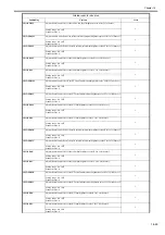
COPIER>ADJUST>FEED-ADJ
Subheading Contents
Level
Summary of Contents for imagePRESS C1
Page 1: ...Oct 22 2008 Service Manual imagePRESS C1 Series ...
Page 2: ......
Page 6: ......
Page 38: ...Contents ...
Page 39: ...Chapter 1 Introduction ...
Page 40: ......
Page 42: ......
Page 72: ...Chapter 1 1 30 F 1 18 ...
Page 85: ...Chapter 1 1 43 T 1 26 ...
Page 88: ......
Page 89: ...Chapter 2 Installation ...
Page 90: ......
Page 94: ......
Page 234: ......
Page 235: ...Chapter 3 Basic Operation ...
Page 236: ......
Page 238: ......
Page 244: ......
Page 245: ...Chapter 4 Main Controller ...
Page 246: ......
Page 248: ......
Page 276: ...Chapter 5 Original Exposure System ...
Page 277: ......
Page 332: ...Chapter 6 Laser Exposure ...
Page 333: ......
Page 342: ...Chapter 6 6 8 F 6 10 1 Laser Light 2 Laser Shutter 3 Laser Shutter Lever 1 1 2 2 1 2 3 3 3 3 ...
Page 344: ...Chapter 7 Image Formation ...
Page 345: ......
Page 431: ...Chapter 7 7 82 ...
Page 462: ...Chapter 8 Pickup Feeding System ...
Page 463: ......
Page 504: ...Chapter 8 8 39 7 F 8 52 8 F 8 53 9 F 8 54 1 3 2 1 2 4 3 1 2 4 3 ...
Page 505: ...Chapter 8 8 40 10 F 8 55 11 F 8 56 12 F 8 57 1 4 2 3 5 4 1 3 2 1 4 2 5 3 ...
Page 506: ...Chapter 8 8 41 13 F 8 58 14 F 8 59 15 F 8 60 5 1 2 3 4 1 2 3 5 4 1 2 3 4 5 ...
Page 507: ...Chapter 8 8 42 16 F 8 61 1 2 3 4 5 ...
Page 509: ...Chapter 8 8 44 3 F 8 64 A Duplexing reversal position 4 F 8 65 2 1 A 2 1 ...
Page 510: ...Chapter 8 8 45 5 F 8 66 6 F 8 67 2 1 2 1 ...
Page 511: ...Chapter 8 8 46 7 F 8 68 8 F 8 69 3 2 1 3 2 1 ...
Page 512: ...Chapter 8 8 47 9 F 8 70 10 F 8 71 3 2 1 2 3 1 ...
Page 513: ...Chapter 8 8 48 11 F 8 72 B Duplexing re pickup stop position 12 F 8 73 3 2 B 1 3 1 2 ...
Page 514: ...Chapter 8 8 49 13 F 8 74 14 F 8 75 1 2 3 1 2 3 ...
Page 516: ...Chapter 8 8 51 F 8 77 SL3 M10 PS17 ...
Page 533: ...Chapter 8 8 68 F 8 154 1 2 4 3 2 3 4 ...
Page 534: ...Chapter 9 Fixing System ...
Page 599: ...Chapter 10 Externals and Controls ...
Page 642: ...Chapter 11 MEAP ...
Page 643: ......
Page 645: ......
Page 695: ...Chapter 12 Maintenance and Inspection ...
Page 696: ......
Page 698: ......
Page 700: ...Chapter 12 12 2 F 12 1 28 9 10 14 13 29 29 11 12 27 6 3 1 2 5 4 7 8 15 16 ...
Page 701: ...Chapter 12 12 3 F 12 2 17 20 24 23 25 26 19 18 24 21 22 ...
Page 704: ...Chapter 12 12 6 F 12 3 1 2 3 4 9 6 5 7 8 11 12 13 14 15 10 ...
Page 715: ...Chapter 12 12 17 F 12 18 1 1 2 2 ...
Page 716: ...Chapter 13 Standards and Adjustments ...
Page 717: ......
Page 719: ......
Page 732: ...Chapter 14 Correcting Faulty Images ...
Page 862: ...Chapter 15 Self Diagnosis ...
Page 894: ...Chapter 16 Service Mode ...
Page 895: ......
Page 1222: ...Chapter 17 Upgrading ...
Page 1223: ......
Page 1225: ......
Page 1256: ...Chapter 17 17 31 F 17 65 2 Turn off the main power switch and remove the USB device ...
Page 1257: ...Chapter 18 Service Tools ...
Page 1262: ......
Page 1263: ......
Page 1264: ...Oct 22 2008 ...
Page 1265: ......


