Diagnose LEDs
There are LEDs present on the outside and the inside of the PRISMAsync controller. The LEDs can
be used to diagnose a problem.
Network Status LEDs
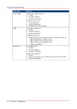
Next to each Ethernet connector there are 2 LEDs indicating the network speed.
When data is transferred, the appropriate LED will blink to indicate network activity.
•
No LED activity on upper Ethernet connector
.
There is no connection to the customer network.
• Check if cables are connected correctly in the PRISMAsync controller and wall outlet.
• Check if cable is not defect.
• Check if normal and crossover Ethernet cables are not exchanged.
• Check if the network is functioning.
•
No LED activity on lower Ethernet connector.
There is no connection between the copier and the PRISMAsync controller.
• Check if cables are connected correctly in the PRISMAsync controller and wall outlet
• Check if cable is not defect
• Check if normal and crossover Ethernet cables are not exchanged.
LED in power button
In the power on/off button on the front side of the PRISMAsync controller a LED is integrated.
If the PRISMAsync controller is switched on this LED is shining blue.
If the LED remains off check the following:
• Does the PRISMAsync controller switch on? If so there is probably an open connection in the
LED wiring.
• If the PRISMAsync controller cannot be switched on or off then there is either a problem with
the wiring of the button or with the power supply.
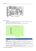
LEDs on AUX control board
On the AUX control board you can find some LEDs. These LEDs indicate the presence of power
on the board. All LEDs should be shining green. If one of the LEDs is off, the board will not
function.
Please first check the connectors and the cables before replacing the board.
The function of the LEDs are:
• 3.3 Volt
• 5 Volt
• 12 Volt
• 24 Volt
NOTE
The board is mounted upside down in the PRISMAsync controller so it might be difficult to check
the boards.
Diagnose LEDs
Chapter 10 - Troubleshooting
125
Summary of Contents for imagePRESS C800 Series
Page 2: ...Edition 2015 04 GB ...
Page 6: ...Contents 6 ...
Page 7: ...Chapter 1 Preface ...
Page 10: ...Preface 10 Chapter 1 Preface ...
Page 11: ...Chapter 2 Introduction ...
Page 13: ...Chapter 3 Installation ...
Page 31: ...Chapter 4 Using the PRISMAsync ...
Page 44: ...Engine service mode during printing 44 Chapter 4 Using the PRISMAsync ...
Page 53: ...Chapter 5 Start shutdown and restart the system ...
Page 61: ...Chapter 6 The Settings Editor ...
Page 64: ...The Settings editor 64 Chapter 6 The Settings Editor ...
Page 65: ...Chapter 7 Service procedures ...
Page 82: ...Connect Harness 22W01 82 Chapter 7 Service procedures ...
Page 83: ...Chapter 8 Firmware upgrades via PRISMAsync ...
Page 103: ...Chapter 9 System software ...
Page 118: ...Configure the machine for the USA 118 Chapter 9 System software ...
Page 119: ...Chapter 10 Troubleshooting ...
Page 140: ...Escalation procedure 140 Chapter 10 Troubleshooting ...
Page 141: ...Chapter 11 Appendix ...
Page 162: ... 26 Picture 2 Engine reports 162 Chapter 11 Appendix ...
Page 167: ......


