R
EPLACING
PARTS
44
T
O
REPLACE
THE
USER
INTERFACE
BOARD
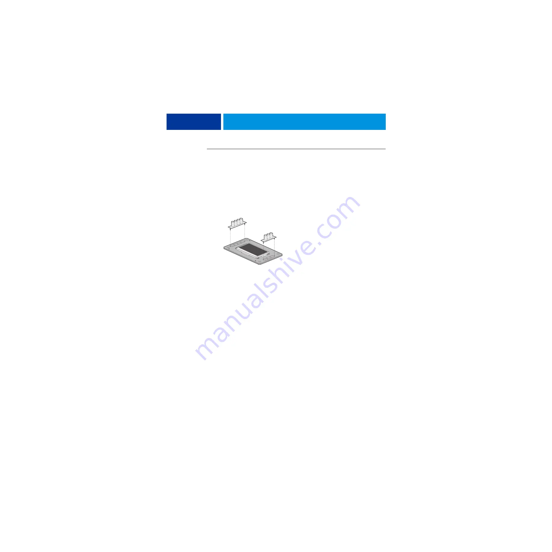
1 If you are installing a new UIB, correctly orient the UIB buttons, and then mount them on the
new UIB.
The UIB buttons attach directly to the front of the UIB and extend through channels in the
top panel. When correctly positioned, the buttons make contact with the button pads on the
front of the UIB and provide users with manual status and control capability from the control
panel.
Use needlenose pliers to pull the button tabs carefully through the anchoring holes in the UIB
until the buttons are secured in place.
F
IGURE
14:
Removing/replacing the UIB buttons
2 Attach the UIB cable to the connector on the back of the UIB (see
).
3 Turn the top panel over to expose its underside and place it on a padded surface.
4 Position the plastic lens around the display window of the UIB.
5 Secure the UIB to the underside of the top panel.
Grasp the UIB in one hand while using the other hand to hold the plastic lens steady against
the UIB display window. Place the UIB in the mounting area of the top panel and carefully fit
the buttons through the cutouts in the top panel as you hold the plastic lens in place.
Replace the four screws that secure the UIB to the underside of the top panel. Be sure to use
the same screws that you removed earlier.
6 If you are replacing the UIB cable with a new cable, do the following:
If present, cut the clamp securing the old cable to the underside of the top panel and remove
the old cable. Attach a new UIB cable to the connector on the UIB. If a new tie-wrap is
included in the new UIB cable spare kit, use it to secure the new UIB cable to the underside
of the top panel.
7 Replace the top panel (see
).
Route the UIB cable through the chassis and connect it to the motherboard connector (see
8 Reassemble the imagePRESS Server and verify its functionality (see
).


