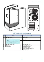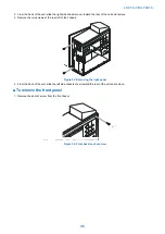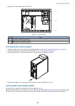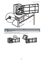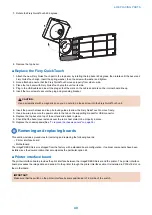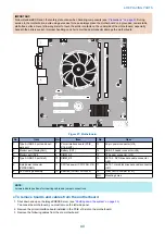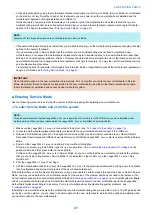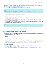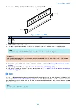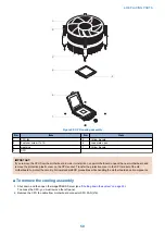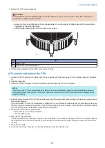
2. Release the six tabs and pull the front bezel off.
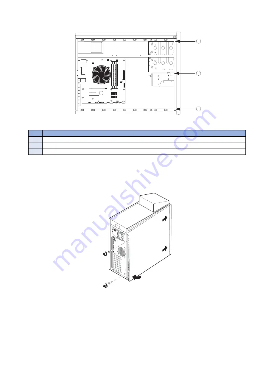
1
2
3
Figure 25: Front bezel tabs
No.
ITem
1
Top tab (one on each side of bezel)
2
Middle tab (one on each side of bezel)
3
Bottom tab (one on each side of bezel)
■ To replace the chassis panels
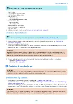
1. Attach the front bezel to the front of the unit snapping tight the six tabs. See
“To remove the front panel” on page 35
2. Insert the anchor screw to secure the front bezel. See
“To remove the front panel” on page 35
.
3. Slide the right chassis cover into place and secure with two screws on backside of the unit.
4. Slide the left chassis cover into place and secure with two screws on backside of the unit.
■ Fiery QuickTouch display module
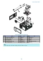
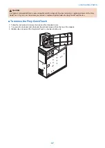
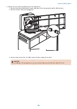
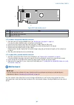
Fiery QuickTouch is attached to the top panel of the
imagePRESS Server
.
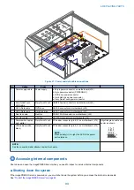
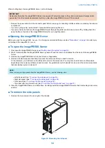
Follow the directions to remove the chassis covers. See
“Opening the imagePRESS Server” on page 34
. You will need to remove
the side covers, then the front cover before you will be able to release the top bezel with the Fiery QuickTouch attached.
4. REPLACING PARTS
36
Summary of Contents for ImagePRESS Server H350 V2
Page 8: ...Introduction 1 Introduction 2 Specifications 7 ...
Page 17: ...INSTALLING HARDWARE 2 Installing Hardware 11 ...
Page 26: ...USING THE IMAGEPRESS SERVER 3 Using the imagePRESS Server 20 ...
Page 35: ...REPLACING PARTS 4 Replacing parts 29 ...
Page 86: ...INSTALLING SYSTEM SOFTWARE 6 Installing System Software 80 ...
Page 91: ...TROUBLESHOOTI NG 7 Troubleshooting 85 ...
Page 104: ...INSTALLATION PROCEDURE 8 Installation 98 Removable HDD Kit B5 108 ...

