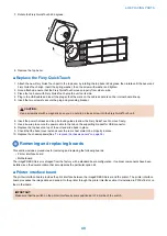
1b
1c
7
1a
1d
3
2
4
5
6
1e
8
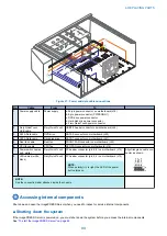
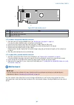
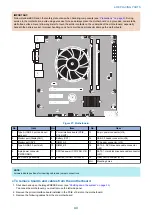
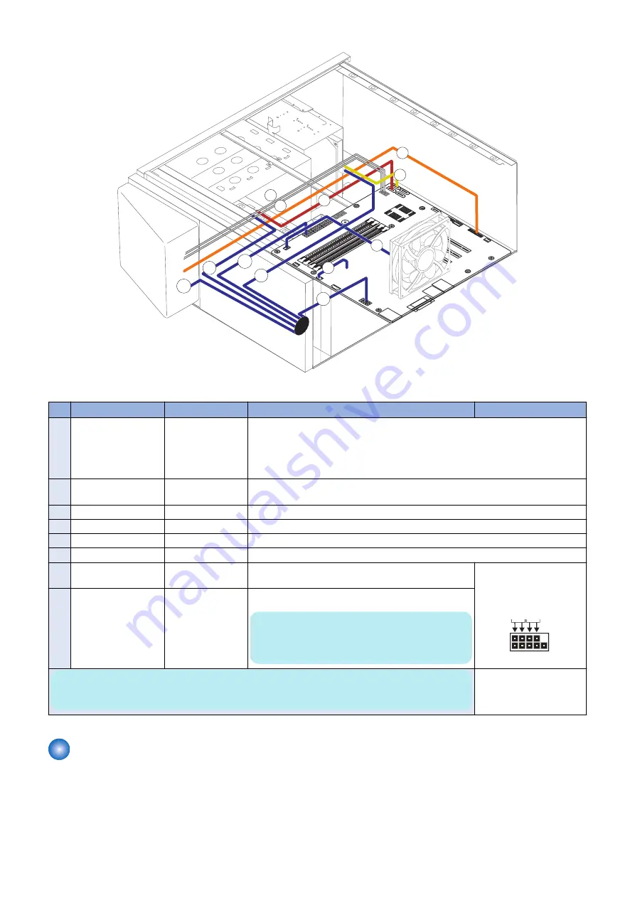
Figure 21: Power and data cable connections
No.
Cable
From
To
1
Power supply cable
Power supply
a. 24-pin power connector on motherboard (J18)
b. 8-pin power connector (PWRCONN1)
c. DVD drive power connector
d. Hard disk drive power connector
e. Fiery QuickTouch power connector
2
Fiery QuickTouch
USB cable
Fiery QuickTouch
USB3.0 header connector on motherboard (J26)
3
SATA Data cable
DVD drive
SATA 0 connector on motherboard (J50)
4
SATA Data cable
Hard disk drive
SATA 1 connector on motherboard (J41)
5
Rear fan cable
Rear fan
FRONT FAN connector on motherboard (J20)
6
CPU fan cable
CPU fan
CPU FAN connector on motherboard (J16)
7
Power switch cables
(red, white)
Fiery QuickTouch
FP header connector (pin 6, 8) on motherboard (J15)
Align triangle on cable con-
nector as shown.
Bl
ack
W
h
ite
W
h
ite
R
e
d
1
2
9
10
8
LED cables (white,
black)
Fiery QuickTouch
FP header connector (pin 2, 4) on motherboard (J15)
NOTE:
When po/-) is right, the LED of the power
button turns on.
NOTE:
See the connection label attached inside the chassis.
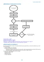
Accessing internal components
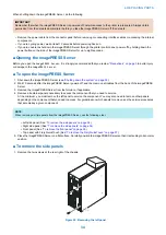
Shut down and open the imagePRESS Server when you need to inspect or service internal components.
■ Shutting down the system
If the imagePRESS Server is powered on, you must shut down the system before you access the internal components.
See
“To start the imagePRESS Server” on page 26
.
4. REPLACING PARTS
33
Summary of Contents for ImagePRESS Server H350 V2
Page 8: ...Introduction 1 Introduction 2 Specifications 7 ...
Page 17: ...INSTALLING HARDWARE 2 Installing Hardware 11 ...
Page 26: ...USING THE IMAGEPRESS SERVER 3 Using the imagePRESS Server 20 ...
Page 35: ...REPLACING PARTS 4 Replacing parts 29 ...
Page 86: ...INSTALLING SYSTEM SOFTWARE 6 Installing System Software 80 ...
Page 91: ...TROUBLESHOOTI NG 7 Troubleshooting 85 ...
Page 104: ...INSTALLATION PROCEDURE 8 Installation 98 Removable HDD Kit B5 108 ...

