Chapter 15
15-38
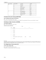
T-15-29
15.13.2 Clearing Counters
0017-6181
iR2022i / iR2025 / iR2030 / iR2018 / iR2022 / iR2018i
- Maintenance/parts counter all clear
Execute service mode > CLEAR > COUNTER to clear all maintenance/parts counters.
- Counter clear on parts replacement
Press the numeric keypad key 0 after displaying the counter for a part just replaced, and the counter will be cleared individually.
15.14 Service Report (REPORT)
15.14.1 Report Output
0017-6185
iR2022i / iR2025 / iR2030 / iR2018 / iR2022 / iR2018i
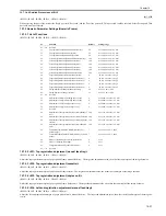
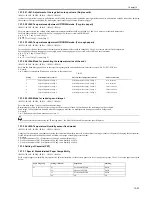
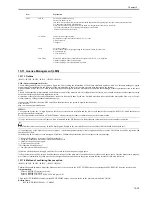
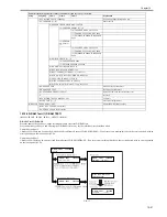
The table below lists the kinds of reports that are supported.
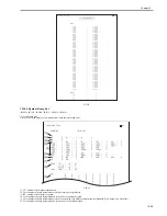
15.14.2 System Data List
0017-6186
iR2022i / iR2025 / iR2030 / iR2018 / iR2022 / iR2018i
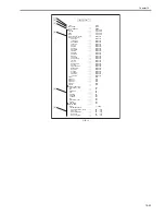
Use it to check the settings associated with the service soft switch and service parameters.
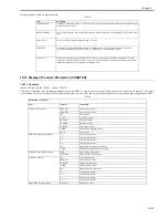
Parts counter list
Item
Counter
Explanation
Service life
DRBL-1 (Unit supplies)
FX-UNIT
Fixing unit paper pass count
150,000
TR-ROLL
Transfer charger roller high-voltage ON count
150,000
DV-UNT-C
Developing unit rotation count
150,000
M-PU-RL
Manual feed tray pickup roller paper pass count
150,000
M-SP-PD
Manual feed tray separation pad paper pass count
150,000
Item
Explanation
SERVICE DATA LIST
Service mode service soft switch output (SSSW, MENU, NUMERIC Param., SPECIAL, NCU, SCAN, PRINT, SYSTEM, ROM,
start date)
SYSTEM DATA LIST
Service mode service soft switch output (SSSW, MENU, NUMERIC Param., SPECIAL, NCU, SCAN, PRINT, SYSTEM, ROM,
start date)
System dump list output
SYSTEM DUMP LIST
Transmission count, reception count, record chart count, error count and other outputs
COUNTER REPORT
Counter output
ERROR LOG LIST
Jam and error history output
SPEC LIST
Type setting, print speed, memory size, ROM indication, adjustment data and other outputs
SERVICE LABEL
Output of an entry format for the service label affixed to the rear cover as shipped
ERDS COM LOG LIST
Output of communication error log information related to e-RDS
ENV. LOG LIST
Output of environmental log information
Summary of Contents for imageRunner 2022
Page 1: ...Aug 8 2007 Service Manual iR2030 2025 2022 2018 Series ...
Page 2: ......
Page 6: ......
Page 20: ...Contents ...
Page 21: ...Chapter 1 Introduction ...
Page 22: ......
Page 57: ...Chapter 1 1 33 ...
Page 60: ......
Page 61: ...T 1 11 ...
Page 64: ......
Page 65: ...T 1 12 ...
Page 68: ......
Page 69: ...Chapter 2 Installation ...
Page 70: ......
Page 72: ......
Page 125: ...Chapter 2 2 53 ...
Page 126: ......
Page 127: ...Chapter 3 Main Controller ...
Page 128: ......
Page 130: ......
Page 142: ......
Page 143: ...Chapter 4 Original Exposure System ...
Page 144: ......
Page 170: ......
Page 171: ...Chapter 5 Laser Exposure ...
Page 172: ......
Page 174: ......
Page 181: ...Chapter 6 Image Formation ...
Page 182: ......
Page 184: ......
Page 196: ......
Page 197: ...Chapter 7 Pickup Feeding System ...
Page 198: ......
Page 217: ...Chapter 8 Fixing System ...
Page 218: ......
Page 220: ......
Page 234: ......
Page 235: ...Chapter 9 External and Controls ...
Page 236: ......
Page 255: ...Chapter 10 RDS ...
Page 256: ......
Page 258: ......
Page 268: ......
Page 269: ...Chapter 11 Maintenance and Inspection ...
Page 270: ......
Page 272: ......
Page 275: ...Chapter 12 Standards and Adjustments ...
Page 276: ......
Page 278: ......
Page 281: ...Chapter 12 12 3 ...
Page 282: ......
Page 283: ...Chapter 13 Correcting Faulty Images ...
Page 284: ......
Page 286: ......
Page 299: ...F 13 11 F 13 12 1 2 3 4 5 6 7 8 9 10 11 12 13 14 15 16 17 ...
Page 300: ......
Page 301: ...Chapter 14 Self Diagnosis ...
Page 302: ......
Page 304: ......
Page 317: ...Chapter 15 Service Mode ...
Page 318: ......
Page 381: ...Chapter 16 Upgrading ...
Page 382: ......
Page 384: ......
Page 411: ...Chapter 17 Service Tools ...
Page 412: ......
Page 414: ......
Page 417: ...Aug 8 2007 ...
Page 418: ......


