25
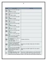
leading to loss of SRAM
contents.
board on which the SRAM is mounted. (Keep in mind
that doing so will lead to loss of all user data.)
E674-
0001
An error has occurred in
communication between the fax
control PCB (2-line) and main
controller PCB.
An attempt to set mode for the
fax device has failed.
1. Check the connection of the cable between the fax
control PCB (2-line) and the main controller PCB. 2.
Replace the ROM DIMM of the fax control PCB (2-
line). 3. Replace the fax control PCB (2- line). 4.
Replace the main controller PCB.
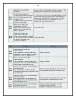
E710-
0001
There is an error in the
initialization of the IPC.
The machine fails to become
ready 3 sec or less after the
IPC chip startup.
Check the cable.
E710-
0002
There is an error in the
initialization of the IPC.
When the main power is turned
on, the communication IC (IPC)
on the DC controller PCB
cannot be initialized.
Check the cable.
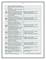
Code
Description
Remedy
E711-
0001
There is an error in the IPC
communication.
The occurrence of an error has been
recorded in the error register of the IPC
chip 4 times or more within 1.5 sec.
Check the cable.
E711-
0002
There is an error in the IPC
communication.
The occurrence of an error has been
recorded in the error register of the IPC
chip 4 times or more within 2 sec.
Check the cable.
E713-
0000
There is an error in the communication
with the finisher.
The communication with the finisher
does not resume within 5 sec after it has
been disrupted.
Check the cable. Replace the DC controller
PCB. Replace the finisher controller PCB.
E716-
0000
There is an error in the communication
with the pedestal.
After the presence of a pedestal has
been detected, the communication fails
to be normal for 5 sec
Check the cable. Replace the DC controller
PCB. Replace the pedestal drive PCB.
E717-
0001
There is an error in the communication
with the NE controller.
The NE controller is not connected at
Check the cable; thereafter, reset the
condition in service mode:
COPIER>FUNCTION>CLEAR> ERR.


