background image

Revision 9.0

imageRUNNER

2530/2525/2520 Series

Service Manual

Summary of Contents for imageRUNNER 2525 Series

Page 1: ...Revision 9 0 imageRUNNER 2530 2525 2520 Series Service Manual ...

Page 2: ...g or short period Canon will issue a new edition of this manual The following paragraph does not apply to any countries where such provisions are inconsistent with local law Trademarks The product names and company names used in this manual are the registered trademarks of the individual companies Copyright This manual is copyrighted with all rights reserved Under the copyright laws this manual ma...

Page 3: ... door and closing the delivery unit door which results in supplying the machine with power 2 In the digital circuits 1 is used to indicate that the voltage level of a given signal is High while 0 is used to indicate Low The voltage value however differs from circuit to circuit In addition the asterisk as in DRMD indicates that the DRMD signal goes on when 0 In practically all cases the internal me...

Page 4: ...up 7 Host machine 7 Option 8 Features 10 Product feature 10 Specifications 11 Specifications 11 Power consumption 12 Weight Size 12 Productivity Print speed 13 Paper type 13 Name of Parts 15 External View 15 Cross Sectional View 550 sheet 1st cassete model 16 Cross Sectional View 250 sheet 1st cassette model 17 Operation 18 Power Switch 18 Control Panel 18 2 Technical Explanation 20 Basic Configur...

Page 5: ...9 List of Clutches Solenoids 120 List of Motors 122 List of Fans 123 List of Switches 124 List of Lamp Heater Others 125 List of Sensors 126 List of PCBs 128 External Internal Cover 130 Removing the Reader Left Cover 130 Removing the Reader Front Cover 130 Removing the Support Cover 130 Removing the Delivery Tray 130 Removing the Front Cover 131 Removing the Lower Left Cover 131 Removing the Left ...

Page 6: ...g the Developing Assembly 151 Removing the Manual Feed Pickup Roller 152 Removing the Manual Feed Separation Pad 152 Removing the Fixing Unit 153 Removing the Cassette Pickup Roller 250 sheet 1st cassette Model 153 Removing the Roller Cassette Separation Pad 250 sheet 1st cassette Model 153 Removing the Cassette Pickup Roller 550 sheet 1st cassette Model 154 Removing the Cassette Feed Roller 550 s...

Page 7: ...t when Replacing the Parts 182 Original Exposure 182 Main Controller 183 Laser Exposure System 184 6 Troubleshooting 185 Initial Check 186 Initial check items list 186 Test Print 188 Overview 188 Select the test print TYPE 188 Troubleshooting Items 189 Troubleshooting items list 189 Image Faults 189 Version Upgrade 194 Overview 194 Procedure 195 Service Call Request Function 198 7 Error Jam Alarm ...

Page 8: ...is Installation Procedure 306 Illustrations Used in This Procedure 306 Symbols in the Illustration 306 Checking before Installation 307 Checking Power Supply 307 Checking the Installation Environment 307 Checking Installation Space 307 Points to Make Before Installation 307 Option Installation Sequence 308 Unpacking 309 Unpacking the Machine and Removing the Packaging Materials 309 Checking the Co...

Page 9: ...ing before Installation 338 Checking the Contents 338 Installation Procedure 338 Cst Heater Kit J1 341 Checking Before Installation 341 Checking the Contents 341 Installation Procedure 341 Checking after Installation 347 Reader Heater Unit 348 Checking Before Installation 348 Checking the Contents For 230V 348 Checking the Parts to be Installed For 120V 348 Installation Procedure 348 Checking afte...

Page 10: ...General Circuit Diagram 550 sheet 1st cassette type 379 General Circuit Diagram 250 sheet 1st cassette type 386 Contents vii ...

Page 11: ...aser Safety 2 Handling of Laser System 2 Turn Power Switch ON 2 Power Supply 3 Safety of Toner 3 Notes When Handling a Lithium Battery 4 Notes Before Servicing 4 Points to Note at Cleaning 4 Notes On Assembly Disassembly 5 ...

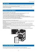
Page 12: ...into an eye during the work The following warnings are given to comply with Safety Principles EN60950 1 Diese Maschine ist der Klasse 1 der Laserprodukte zugeordnet Innerhalb der Maschine wird jedoch ein Laserstrahl der Klasse 3B ausgestrahlt und es ist gefährlich wenn dieser Strahl in die Augen gerät Bei Servicearbeiten am oder in der Nähe des Laserteils zuerst das Hauptgerät abschalten Bei Servi...

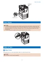
Page 13: ...over untie the cord binding and insert the power plug completely into the extension cord outlet to ensure a firm connection between the power cord and the extension cord 2 The socket outlet shall be installed near the equipment and shall be easily accessible Safety of Toner About Toner The machine s toner is a non toxic material made of plastic iron and small amounts of dye CAUTION Do not throw to...

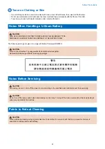
Page 14: ...arnings are given to comply with Safety Principles EN60950 CAUTION Wenn mit dem falschen Typ ausgewechselt besteht Explosionsgefahr Gebrauchte Batterien gemäß der Anleitung beseitigen Notes Before Servicing CAUTION At servicing be sure to turn off the power source according to the specified steps and disconnect the power plug CAUTION Do not turn off the power switch when downloading is under way T...

Page 15: ...hen assembling 5 Unless it is specially needed do not operate the device with some parts removed 6 Never remove the paint locked screws when disassembling 7 During disassembly reassembly or transportation of the printer remove the cartridge if required When the cartridge is out of the printer put it in a protective bag even in a short period of time to prevent the adverse effect of light 8 Ground ...

Page 16: ...Product Overview 1 Product Lineup 7 Features 10 Specifications 11 Name of Parts 15 Operation 18 ...

Page 17: ...ard or optional Printer Model type imageRUNNER 2530 imageRUNNER 2525 imageRUNNER 2520 Print Speed 30ppm 25ppm 20ppm Positioning Target machine imageRUNNER 2025 2022 2018 Series imageRUNNER 2530 2525 2520 Underlined 2 digit numeric figures indicate print speed ppm print per minute 1 Product Overview 7 ...

Page 18: ...y J1 9 FL Cassette AJ1 10 FL Cassette AK1 11 FL Cassette AL1 12 Cassette Heater Unit 37 Cst Heater Kit J1 is required 13 Cassette Module W1 Cassette Spacer A1 is required when installing to 250 Sheets Cassette Model 14 CST Feeding Unit AE1 Cassette Spacer A1 is required when installing to 250 Sheets Cassette Model 15 Envelope Feeder Attachment D1 16 Cassette Spacer A1 17 Inner 2Way Tray G1 For hos...

Page 19: ...ax Board AG1 4 USB Application 3 Port Interface Kit A1 5 Serial Interface Kit J2 6 System Upgrade RAM C1 7 Copy Control Interface Cable A1 8 Barcode Printing Kit B1 PCL Printer Kit AF1 is required PCL Printer Kit AF1 512MB RAM should be installed In the case of 256MB System Upgrade RAM C1 512MB is needed PS Printer Kit AF1 Color Send Kit Y1 Color Send Searchable PDF Kit C1 1 Product Overview 9 ...

Page 20: ...ture Drum unit Highly durable OPC drum is adopted High image quality Laser scanner unit Capable of 1200 dpi Waste toner container User replaceable Low running cost High image quality Low running cost 1 Product Overview 10 ...

Page 21: ...int time imageRUNNER 2530 2525 5 4 sec or less imageRUNNER 2520 6 4 sec or less Paper type Cassette 1 3 4 Weight 64 g m2 to 90 g m2 Type Plain Recycled Color 64 g m2 to 80 g m2 3 hole punch Paper type Cassette 2 Weight 64 g m2 to 90 g m2 Type Plain Recycled Color 64 g m2 to 80 g m2 3 hole punch Envelopes No 10 COM10 ISO B5 Monarch ISO C5 DL The optional Envelope Feeder Attachment D1 is required Pa...

Page 22: ... US 120 127 V AC 50Hz 60Hz 6 2 A imageRUNNER 2530 2525 2520 Except US 220 240 V AC 50Hz 60Hz 3 3 A Maximum power consumption 120 127 V model imageRUNNER 2530 2525 Approx 1 473 kW imageRUNNER 2520 Approx 1 238 kW 220 240 V model imageRUNNER 2520 Approx 1 542 kW imageRUNNER 2530 2525 Approx 1 345 kW At the time of printing 120 127 V model iR2530 2525 550 sheet 1st cassette type Approx 580 1Wh Refere...

Page 23: ...e 2 way unit Plain paper 64 80 19 19 16 16 13 13 Heavy Pa per 81 105 106 128 A3 1 sided Plain paper 64 90 15 15 15 15 15 15 Heavy Pa per 91 105 12 12 12 106 128 6 6 6 2 sided with the 2 way unit Plain paper 64 80 14 14 14 14 14 14 Heavy Pa per 81 105 106 128 2 sided without the 2 way unit Plain paper 64 80 9 9 9 9 9 9 Heavy Pa per 81 105 106 128 Paper type For free size paper refer to the table be...

Page 24: ...1 to 128 A4 A4R A3 A5R B4 B5 B5R LTR LTTR LGL 279mmX432mm 11 X17 STMTR Yes No No No No No Labels A4 B4 LTR Yes No No No No No Transparencies A4 LTR Yes No No No No No 3 hole punch LTR Yes Yes Yes Yes Yes Yes Envelopes No 10 COM10 ISO B5 Monarch ISO C5 DL Yes No Yes No No No Free size 99 mm x 297 mm to 148 mm x 432 mm Yes No No No No No 1 Product Overview 14 ...

Page 25: ...4 Control panel 18 Platen glass 5 Support cover 19 Reader rear cover 6 Delivery tray 20 Rear cover right 7 Front cover 21 Rear cover left 8 Cassette 1 22 Right cover upper rear 9 Cassette 2 standard or optional 23 Right cover lower rear 10 Cassette 3 option 24 Manual feed pickup tray 11 Cassette 4 option 25 Right cover 12 Lower left cover 26 Lower rear cover 13 Left cover 27 Cassette 2 rear cover ...

Page 26: ...l path roller 1 5 Drum unit 20 Feed roller cassette 1 6 Drum cleaning unit 21 Separation roller cassette 1 7 Delivery roller 22 Vertical path roller 2 8 2 way unit 23 Feed roller cassette 2 9 Fixing outlet roller 24 Separation roller cassette 2 10 Fixing film unit 25 Pickup roller cassette 2 11 Pressure roller 26 Primary charging roller 12 Duplex feed roller 1 27 Developing unit 13 Photosensitive ...

Page 27: ...1 4 Toner bottle 19 Vertical path roller 1 5 Drum unit 20 Vertical path roller 2 6 Drum cleaning unit 21 Feed roller cassette 2 7 Delivery roller 22 Separation roller cassette 2 8 2 way unit 23 Pickup roller cassette 2 9 Fixing outlet roller 24 Primary charging roller 10 Fixing film unit 25 Developing unit 11 Pressure roller 26 Sub hopper 12 Duplex feed roller 1 27 Laser scanner unit 13 Photosensi...

Page 28: ...ff the power turn off the Main power Switch Conventional shutdown sequence operation is not required After power off After the Main power Switch is turned off do not reactivate the Main power Switch until a screen disappears do not turn off the power while download is processing Control Panel 1 2 3 4 5 6 7 8 9 10 11 12 15 16 13 14 17 18 No Part name No Part name 1 Touch panel display 10 Stop key 2...

Page 29: ...opy Send or Fax Send or Fax Scan Scan or Direct print System Monitor System Monitor Settings Registration menu 6 7 8 9 1 2 3 4 5 1 Common Settings 6 Copy Settings 2 Timer Settings 7 Communications Settings 3 Adjustment Cleaning 8 Printer Settings 4 Report Settings 9 Address Book Settings 5 System Settings Difference of Settings Registration menu imageRUNNER 2030 2025 2022 2018 Series imageRUNNER 2...

Page 30: ...Technical Explanation 2 Basic Configuration 21 Original Exposure System 23 Controller System 36 Laser Exposure System 47 Image Formation System 53 Fixing System 66 Pickup Feed System 76 Embedded RDS 97 ...

Page 31: ...am Reader relay PCB CIS Exposure lamp Document exposure system Main controller DC controller Option board Controller system Duplexing feed Delivery Transfer Pickup Fixing Fixing system Image formation system Pickup feed system Laser exposure system Cassette 2 Cassette 1 Laser scanner unit Basic Sequence Sequence at Power On Reader Backwarding Main power switch ON SREADY STBY Scanner motor LED CIS ...

Page 32: ...FW STBY STBY Scanner motor LED CIS HP sensor Black shading White shading Leading edge of original Shading position Shading position Trailing edge of original Forwarding Backwarding Forwarding Light ON ON ON 2 Technical Explanation 22 ...

Page 33: ...nge by carriage travel image process on main controller PCB 1 In ADF mode original feed speed change image process on main controller PCB 1 Lens Rod lens array CMOS sensor Number of lines 1 Number of pixels Total 7488 incl 7276 effective pixels Maximum original scan width 297mm CIS drive control Drive control by reader motor M31 Original size de tection In book mode Main scanning direction by refl...

Page 34: ...sure by LED LED photoconductive body Reader Heater H5 Prevents condensation on the copyboard glass Reader relay PCB PCB2 Controls the reader unit drive and image process Reader relay PCB The function configuration of reader relay PCB is described below J551 J560 J559 J552 J562 J561 J553 J554 J555 IC2 IC7 J557 J558 J563 J556 Jack No Description J551 Receives power from the machine printer unit J552...

Page 35: ...k mode 1 original Backward movement Forward movement Start key ON SCRW SCFW STBY STBY Scanner motor M31 LED CISHP sensor S31 Black shading White shading Leading edge of original Shading position Shading position Trailing edge of original Original glass reading start position 1 Moves to the start position after black shading white shading 3 Moves to the standby position 2 Original scan Shading posi...

Page 36: ...trols Controlling the Scanner Drive System Overview Parts configuration of scanner drive is described below Forward movement Backward movement Sensor shading plate Carriage CISHP sensor S31 Scanner motor M31 Contact image sensor CIS Original glass cover open close sensor rear S33 Original glass cover open close sensor front S32 Guide shaft Carriage drive belt Reader relay PCB PCB2 Scanner motor M3...

Page 37: ...lled by controlling the motor as shown below Start position position Acceleration Original leading edge Normal speed Original trailing edge Deceleration Stop Shift speed Shift distance 1 2 3 4 1 Acceleration area Accelerates until a speed suited to the selected mode is reached 2 Run up speed area Run up margin to ensure a stable speed 3 Image reading area Reads an image at a specific speed 4 Decel...

Page 38: ...h the rod lens array Analog Control Performed by the CIS The flow of analog image processing performed by the contact image sensor CIS is as follows 1 The light reflected by the original is collected by the rod lens array 2 The light is received by the CMOS sensor array 3 The CMOS sensor array converts the received light to an electric signal and outputs it The CMOS sensor array consists of four c...

Page 39: ...roller PCB 2 When magnification is increased to 100 200 The original scan speed in the Book mode original feed speed when the ADF is used is changed within the range of 123 mm sec to 61 5 mm sec depending on the selected magnification rate Data is not processed on the main controller PCB Detecting the Size of Originals Overview The original size is identified by the combination of presence and abs...

Page 40: ...nsor 1 Original sensor 2A Original sensor 3 Original sensor 0 Outline of Original Size Detection In the BOOK mode One sheet of original A4R is set and the copyboard cover or ADF is closed 1 Standby state Original sensor Turns off Reader unit Copyboard cover Original sensor 3 Copyboard glass Original sensor 2A Original sensor 1 Original sensor 0 2 The copyboard cover opens at an angle of more than ...

Page 41: ...tical Note that a wrong original size may be identified because the sensor output level does not change in the following cases When the original is A3 sized black When the original is a book its thickness does not allow the copyboard cover to close fully making it difficult to detect the sensor level change When the copyboard cover is not closed fully the sensor level change is not detected after ...

Page 42: ...ction change the following setting of the paper size group if necessary 3 SYSTEM SYSTEM Numeric 057 Setting value 1 AB configuration 2 A configuration 3 Inch configuration 4 AB Inch configuration Dirt Sensor Control Overview The machine changes the original read position or corrects the read image depending on the presence absence of dust on the stream reading glass or ADF platen roller thus preve...

Page 43: ...t The original is read at the position determined at job end or start If presence of dust is detected there the read image is corrected Point Description A Read reference position B About 0 5 mm from the reference position to the inside of the roller C About 1 0 mm from the reference position to the inside of the roller Image Processing Overview Major specifications and functions of the image proc...

Page 44: ... reader relay PCB in parallel for each channel total four channels of the CMOS sensor array CMOS sensor 1 CMOS sensor 4 CMOS sensor 3 H L L H H L H L H H L output Light receiving block CMOS Sensor Output Gain Correction and Offset Correction The analog video signals output from the CMOS sensor are corrected so that they will have a specific gain level gain correction and the output voltages genera...

Page 45: ...rrection for each scan It measures the density of the standard white plate and compares the measured value with the target value stored in the shading correction circuit to use the difference between the two as the shading correction value The machine uses this shading correction value to correct the variation among CMOS sensor pixels when scanning the original thus evening out the image density l...

Page 46: ...or FAX USB extension hub interface Image memory SO DIMM Temporary saving of image data Capacity 256MB maximum 512 MB Flash ROM Stores system software Boot ROM 16 MB Program ROM 128 MB SRAM Stores user data service data information USB port USB2 0 device I F USB2 0 host I F Ethernet port Ethernet I F SD card slot SD I F Secondary battery Installed only in the machine supporting the FAX or the SEND ...

Page 47: ...onnector J8116 SOFT ID board connector J8117 Control card connector J8118 Serial interface connector J8119 Card reader connector J8124 Secondary battery unit connector J8125 Power supply connector J8127 NCU board connector J8134 Pseudo CI connector J8140 Serial interface connector J8142 Laser scanner unit connector J8143 Laser scanner unit connector J8146 Pseudo CI connector J8147 NCU board connec...

Page 48: ... of the Image Processing Module Main controller PCB Processes image data for output to the printer unit Printer unit output image processing block DC controller PCB Reader relay PCB SO DIMM image memory program temporary storage Processes the image data read by the reader unit Reader unit input image processing block 2 Technical Explanation 38 ...

Page 49: ...o density conversion density adjustment F adjustment gamma correction Main controller PCB Reader unit Compressio Extesion Editing Block Main controller PCB to printer unit output image processing block Enlargement reduction Rotation Integration Compression Expansion Reader image processing block PDL image processing block SO DIMM 2 Technical Explanation 39 ...

Page 50: ... Binary density conversion Enlargement reduction Smoothing Flow of Image Data According to Copy Functions Main controller PCB Image processing block for printer unit Image processing block for reader unit Reader unit Data compression Data rotation Data expansion SO DIMM DC controller PCB 2 Technical Explanation 40 ...

Page 51: ...expansion Resolution conversion SO DIMM USB2 0 To network compression data Ethernet port Flow of Image Data for the Fax Transmission Image processing block for reader unit Image processing block for FAX Super G3 Fax Board Main controller PCB Data rotation Data compression Data expansion SO DIMM Reader unit 2 Technical Explanation 41 ...

Page 52: ...PCB Flow of Image Data for the PDL Function Rendering processing block Compression expansion editing block Processing block for printer unit DC controller PCB Main controller PCB SO DIMM Ethernet PDL Software counter The timing at which the count is incremented differs depending on the following Printing mode single sided double sided 2nd side or double sided 1st side Target of delivery inner fini...

Page 53: ...me Function Error code FAN3 Exhaust fan rear Cools the fixing unit E805 0000 E805 0001 FAN4 Exhaust fan front Cools the fixing unit E805 0002 E805 0003 FAN6 Power supply cooling fan Cools the power supply E804 0000 E804 0001 PTINT LSTR STBY STBY WUP INI 1 60sec Exhaust fan rear FAN3 Exhaust fan front FAN4 Power supply cooling fan FAN6 N6 Full speed 1 2 speed 1 The fan operates at 1 2 speed only wh...

Page 54: ... 24V 5VR 24VR 5VC USB HUB Kit Interlock switch SW2 24VR 24VU 24VR 24VR Reader relay PCB ADF CIS Main controller PCB DC controller PCB 24VR 5VR 24VR 5VC 24VU 24VR 24VS 5VR 3 3V 5VC 3 3V 5VR Regulator 3 3V 3 3V 5VC Modem PCB VH PCB HVT PCB Laser scanner unit 5VC 12VR No 2 deleivery unit 5VR 3 3V 3 3V 24VR 24VR 24VR Cassette pedestal Inner finisher 5VR 24VU 24VR Option 3 3V 24VR 3 3V 24VR Regulator 1...

Page 55: ...C 24VU 24VR 24VS 5VR 3 3V 5VC 3 3V 5VR Regulator 3 3V 3 3V 5VC Modem PCB VH PCB HVT PCB Laser scanner unit 5VC 12VR No 2 deleivery unit 5VR 3 3V 3 3V 24VR 24VR 24VR Cassette pedestal Inner finisher 5VR 24VU 24VR Option 3 3V 24VR 3 3V 24VR Regulator 12VR SW drive circuit Environment SW Connection to Options Reader ADF Inner finisher Wiring inside the machine 2 cassette pedestal The inner finisher i...

Page 56: ...ting or ready to start operating with all power supplies provided Energy saving mode Only the LCD backlight for the control panel is turned off The machine enters this mode when auto sleep timer is activated in the user mode or the energy saving key is pressed Sleep 1 The controller is powered but the engine is not powered Sleep 2 The controller is not powered The sleep 2 mode is transitioned to t...

Page 57: ...n scanning direction synchronous control Laser intensity control APC control Others Laser ON OFF control Laser scanner motor control Laser shutter control Main Configuration Parts 1 2 4 3 No Name Function 1 Laser Unit Emits laser 2 Polygon mirror Scans the laser light in the main scanning direction 3 BD mirror Reflects the laser light in the BD PCB direction 4 BD PCB Generates the BD signa Control...

Page 58: ...r control signal CTRL0 2 C D laser control signal Scanner motor control signal Signal name Function POLYGON_M_FG FG output signal POLYGON_M_ACC Motor speed up signal POLYGON_M_DEC Motor speed down signal BD signal Signal name Function BD BD signal Basic Sequence When the control panel power switch is turned on the laser scanner starts to rotate when the motor rotationreaches its target revolution ...

Page 59: ... Laser control signal Laser status CNT1 2 CNT1 1 CNT1 0 C Laser D Laser 0 1 0 ON For APC control OFF 0 1 1 OFF OFF 0 0 1 OFF ON For APC control 0 1 1 OFF OFF 1 1 1 Video signal entry arrowed Video signal entry arrowed 0 1 1 OFF OFF 0 0 1 OFF ON For APC control 0 1 1 OFF OFF J8142 CTRL0_2 CTRL0_1 CTRL0_0 Main Controller PCB Main Scanning Synchronous Control The synchronous control in the main scann...

Page 60: ... is generated based on the light from laser C Controlling the Intensity of Laser Light APC Control The machine monitors the laser light that is emitted to the built in photo diode of laser diode and adjusts the laser to appropriate intensity Controlling the Laser Scanner Motor From when the laser scanner motor starts and the laser scanner motor reaches the number of target rotation to before image...

Page 61: ...rks in conjunction with the right door and the laser light is blocked Also whenthe front door or right door open is detected laser scanner motor and the laser emission will be turned OFF 1 2 2 2 1 3 3 1 DOOR CLOSED DOOR OPEN No Part name 1 Laser shutter 2 Laser shutter link works in conjunction with the right door 2 Technical Explanation 51 ...

Page 62: ...No Part name 3 Laser unit 2 Technical Explanation 52 ...

Page 63: ...o 700V DC bias switch control variable according to density setting environment sensor detection Developing cylinder diam eter φ20 Toner Magnetic negative toner Toner level detection Toner detection by toner level sensor inside sub hopper and developing unit Transfer Transfer method Transfer roller DC constant current control approx 20 µA Cleaning bias control 2700V DC constant voltage control DC ...

Page 64: ...parated from the photo sensitive drum 9 Transfer roller Applies positive charge to the back of a paper to cause the toner to be transferred to it 10 Developing cylinder Transfers the toner in the developing unit to the photosensitive drum 11 Developing unit Unit consisting of the developing cylinder developing blade etc 12 Toner feed screw Inside developing unit Feeds the toner supplied from the s...

Page 65: ... visible image 4 Transfer block Applies positive charge to the back of a paper to transfer the toner on the drum to the paper 5 Separation block Separates a paper from the photosensitive drum with its elastic force and at the same time applies negative charge to the back of paper to facilitate paper separation 6 Drum cleaning block Scrapes off the residual toner on the surface of the drum using th...

Page 66: ...ge formation sequence 1st sheet Image formation sequence 2nd sheet and later Sheet to sheet sequence Registration ON Registration ON Image write end Sequence of Operation last rotation Image write end Primary charging AC bias Main Motor M1 Primary charging DC bias Laser Developing AC bias Developing DC bias Developing cylinder clutch CL3 Transfer bias Static eliminator bias 1 In 1 above a cleaning...

Page 67: ...M1 Main motor 1 Main motor drive signal Primary Charging Bias Control The machine is directly charged by the charging roller DC bias and AC bias that stabilized the charge is applied to the primary charging roller Photosensitive drum 2 Environment sensor 1 Primary charging roller HVT PCB Primary DC bias control circuit Primary AC bias control circuit DC Controller PCB No Part name 1 Primary chargi...

Page 68: ... screw and toner agitation plate The toner presence absence in the drum unit is detected by the developing unit toner sensor TS1 which is a magnetic permeability sensor Toner feed screw Developing cylinder Developing Blade M1 3 TS1 2 Toner agitation plate CL3 1 DC Controller PCB No Part name No Part name TS1 Developing unit toner sensor 1 Developing cylinder clutch drive signal CL3 Developing cyli...

Page 69: ...control the DC bias and AC bias applied to the developing cylinder to keep their voltage at the fixed level DC bias switch control The DC bias output varies according to the environment or density setting detected by the environment sensor HU1 Toner Container Outline Toner cartridge is filled with toner and supplies to the drum unit Toner cartridge The toner in the toner cartridge is fed to the su...

Page 70: ...ridge is assumed and the message to replace the toner cartridge will be displayed Also if the developing unit toner sensor TS1 keeps detecting the absence of the toner for more than the specified period of time no toner in the developing unit is assumed and a No Toner error message will be displayed Toner cartridge Sub hopper Toner feed screw Developing unit M1 1 3 M6 4 M7 2 TS2 Route of toner sup...

Page 71: ...TS1 TS2 Replace the toner car tridge Job is stop ped No If the developing unit toner sensor TS1 keeps detecting the absence of the toner for more than 40 sec after the drive of the hopper motor M7 has been started a message is displayed in the bottom of con trol panel because the system determines that there is no to ner in the toner cartridge The print operation stops After the toner cartridge is...

Page 72: ...he toner container a signal is notified of Related error code E020 0000 The path between the sub hopper and the developing unit is clogged with toner E024 0000 The connector J207 of developing unit toner sensor TS1 is disconnected E024 0001 The developing unit toner sensor TS1 is disconnected E025 0000 The connector J207 of sub hopper toner sensor TS2 is disconnected E025 0001 Failure of the bottl...

Page 73: ...ntrol To return the toner adhered on the transfer roller to the photosensitive drum negative voltage is applied at the last rotation Separation Static Eliminator Bias Control Either of the two types of negative voltage low bias or high bias is applied to the static eliminator depending on the print mode and sequence for reducing electrostatic suction to facilitate separation of paper from the phot...

Page 74: ...ne is stopped Replace the waste toner container When the Switch is pressed and the total counter value fails 50 000 sheets 3 Waste toner full When replacing it for a new waste toner container after the waste toner full sensor detected presence of a waste toner container the internal counter for full detection is cleared automatically And the warning indication message on the operation panel disapp...

Page 75: ...When attaching a waste toner container that has been used by the other machine or the counter information is lost for some reason it is necessary to notify full level before an alert is given The counter shows less than 50 000 although the sensor detects full level of waste toner In such a case it is determined as full level without an alert and the machine cannot continue printing Explain the use...

Page 76: ... sec 1 1 slow speed 3 1 speed down Fixing heater Ceramic heater Control temperature 208 deg C plain paper 1 Temperature detection By the main thermistor and the sub thermistor Cleaning mechanism Cleaning roller Edge heat rising prevention control Down sequence control Fixing loop control Loop sensor Protective Function Main thermistor and Sub thermistor Thermo Switch operating temperature 250 deg ...

Page 77: ...in thermistor To be in contact with the heater Temperature control detection of abnormal temperature rise TH2 Sub thermistor rear To be in contact with the heater non feeding area Temperature control detection of abnormal temperature rise temperature de tection cooling control on the edges TP1 Thermo Switch To be in contact with the heater non feeding area Temperature control detection of abnormal...

Page 78: ...rting print Flying start temperature control Print temperature control To increase temperature to meet the fixing target temperature and keep the target temperature during printing Startup warm up rotation temperature control Print temperature control Sheet to sheet temperature control Down sequence control To prevent fixing failure due to rising temperature at the edge or fall in temperature This...

Page 79: ...stor is less than 100 deg C When the original sheet is set on the ADF tray and also the detection temperature of the main thermistor is less than 100 deg C When the main power switch is turned ON or the machine condition is shift from the sleep mode to standby and also the detection temperature of the main thermistor is less than 155 deg C Control description The target control temperature is set ...

Page 80: ...erature is specified depending on the paper type paper size elapsed time since the last control including the standby control of fixing temperature and fixing temperature at the start of warm up control 2 Temperature control during printing When the paper passes in the fixing unit the fixing temperature is controlled to keep the target value see the table on the next page according to the detectio...

Page 81: ...sette feeding PRINT SW 63 Control temperature in Heavy Heavy H Bond paper modes PRINT SW 166 Control temperature for the second side of 2 sided copying PRINT SW 173 Control temperature for the second side of 2 sided copying PRINT SW 179 Control temperature in Postcard S Postcard Envelope modes Setting value 0 to 2 15 deg C 3 to 11 12 to 15 deg C each 3 deg C Default 7 12 to 14 15 deg C Down sequen...

Page 82: ...3 13 4 3 8 10 10 10 4 4 4 4 4 4 4 Bond paper Normal 8 8 8 8 8 1 8 8 8 8 8 2 8 8 8 8 8 3 8 8 8 8 8 4 4 4 4 4 4 OHP Normal 13 27 25 20 17 17 13 1 13 27 25 20 17 17 13 2 10 27 25 20 14 14 10 3 8 10 10 10 8 4 4 4 4 4 4 Postcard Normal 12 1 10 2 8 3 8 4 4 S Postcard Normal 6 1 5 2 4 3 4 4 2 Envelope Normal 10 1 8 2 6 3 6 4 3 Completion conditions When the fixing temperature reaches 175 deg C and lower ...

Page 83: ...ixing temperature Completion conditions When the detected temperature of the sub thermistor reaches 170 deg C and less 1 1 It is different according to setting value of the user mode Special mode S or Rotation collation adjustment User mode related to fixing grade The fixing grade is affected by some special modes in user mode which change the control temperature or productivity The related modes ...

Page 84: ...tation colla tion adjustment mode The down sequence time is reduced in the collation adjustment mode The fixing grade is reduced and productivity is im proved Image Priority Default Temperature difference between the main and sub thermistors to start the paper feeding 20 deg C Speed Priority 1 Productivity is improved Temperature difference between the main and sub thermistors to start the paper f...

Page 85: ...fied value during startup control Yes E001 Fixing unit temperature rise detection 0000 The reading of the main thermistor is 250 deg C or more continuously for 200 msec Yes 0001 The hardware circuit detects overheating of the main or sub thermistor for 200 msec Yes 0002 The reading of the sub thermistor is 295 deg C or more continuously for 200 msec Yes E002 Fixing unit temperature insufficient ri...

Page 86: ... Manual feed pickup tray 100 sheets 80 g m2 100 sheets 64 g m2 Paper feed reference Center reference Paper size Cassette 1 3 4 A4 A4R A3 A5R B4 B5 B5R LTR LTTR LG 11 x 17 STMTR Cassette 2 A4 A4R A3 A5R B4 B5 B5R LTR LTTR LG 11 x 17 STMTR Envelopes No 10 COM10 ISO B5 Monarch ISO C5 DL The optional Envelope Feeder Attachment D1 is required Manual feed pickup tray A4 A4R A3 A5R B4 B5 B5R LTR LTTR LG ...

Page 87: ...12 Fixing pressure roller 3 Vertical path slave roller 1 13 Fixing film 4 Pickup roller cassette 1 14 Fixing outlet roll 1 5 Manual feed pull up roller 15 Fixing outlet roll 2 6 Manual feed pickup roller 16 Duplexing inlet roller 7 Registration roller 17 Vertical path slave roller 2 8 Transfer roller 18 Tray 1 delivery roller 9 Duplexing feeding roller 2 19 Tray 2 delivery roller 10 Drum 20 Revers...

Page 88: ... Fixing film 3 Vertical path slave roller 1 13 Fixing outlet roll 1 4 Manual feed pull up roller 14 Fixing outlet roll 2 5 Manual feed pickup roller 15 Duplexing inlet roller 6 Registration roller 16 Vertical path slave roller 2 7 Transfer roller 17 Tray 1 delivery roller 8 Duplexing feeding roller 2 18 Tray 2 delivery roller 9 Drum 19 Reversing roller 10 Duplexing feeding roller 1 2 Technical Exp...

Page 89: ...e 1 pickup sensor S7 Duplex feed sensor S2 Cassette 1 paper sensor S9 Manual feeder paper sensor S3 Cassette 1 paper level sensor A S12 No 1 delivery sensor S4 Cassette 1 paper level sensor B S19 Fixing outlet sensor S5 Pre registration sensor S40 Reversal sensor S6 Loop sensor S42 No 2 delivery sensor 2 Technical Explanation 79 ...

Page 90: ... S42 S40 No Part Name No Part Name S2 Cassette 1 paper sensor S12 No 1 delivery sensor S5 Pre registration sensor S19 Fixing outlet sensor S6 Loop sensor S40 Reversal sensor S7 Duplex feed sensor S42 No 2 delivery sensor S9 Manual feeder paper sensor 2 Technical Explanation 80 ...

Page 91: ...Name No Part Name M1 Main motor SL4 Reversal solenoid M2 Fixing motor SL5 No 2 delivery solenoid M10 Reversal motor CL1 Registration clutch SL1 Pickup solenoid CL2 Manual feed pickup clutch SL2 Manual feed pickup solenoid CL4 Duplex feed clutch SL3 No 1 delivery reversal solenoid 2 Technical Explanation 81 ...

Page 92: ...Name No Part Name M1 Main motor SL4 Reversal solenoid M2 Fixing motor SL5 No 2 delivery solenoid M10 Reversal motor CL1 Registration clutch SL1 Pickup solenoid CL2 Manual feed pickup clutch SL2 Manual feed pickup solenoid CL4 Duplex feed clutch SL3 No 1 delivery reversal solenoid 2 Technical Explanation 82 ...

Page 93: ...of Paper Paths w 2 Way Unit inaner 2 way tray 550 sheet 1st cassette model Pickup from cassette 1 Pickup from manual feeder Delivery to tray 1 Delivery to tray 2 option Reversing point 2 Technical Explanation 83 ...

Page 94: ... 250 sheet 1st cassette model Pickup from cassette 1 Pickup from manual feeder Delivery to tray 1 Delivery to tray 2 option Reversing point 2 Technical Explanation 84 ...

Page 95: ... Diagram of Paper Paths w o 2 Way Unit 550 sheet 1st cassette model Pickup from manual feeder Pickup from cassette 1 Delivery to tray 1 Reversing point 2 Technical Explanation 85 ...

Page 96: ...te 1 Delivery to tray 1 Reversing point Controls Overview Duplex Feed Control Fixing Registration Assembly Multi Purpose Pickup Assembly Cassette Pickup Assembly Area Detection Control Cassette Pickup Assembly Outline Paper Level Presence Detection 2 Technical Explanation 86 ...

Page 97: ... the separation roller and moved as far as the registration roller by the pickup vertical path roller The pickup vertical path roller pickup roller feed roller and separation roller are driven by the cassette pickup motor M1 4 1 2 3 5 No Part name No Part name 1 Pickup roller 4 Pickup vertical path roller 2 Feed roller 5 Lifter plate 3 Separation roller Paper Size Detection Paper size of the casse...

Page 98: ...N ON 0 0 0 0 0 16K 270 0 195 0 0 ON ON 0 ON 0 0 0 A5 R 148 5 210 0 ON 0 ON 0 ON ON 0 0 A4 297 0 210 0 0 ON 0 0 ON ON 0 0 STMT R 139 7 215 9 ON 0 ON 0 ON ON 0 0 LTR 279 4 215 9 0 ON ON 0 ON ON 0 0 B5 R 182 0 257 0 ON 0 ON 0 0 ON ON ON LTR R 215 9 279 4 0 0 ON 0 ON 0 0 ON A4 R 210 0 297 0 0 0 ON 0 0 ON ON 0 LGL 215 9 355 6 0 0 ON 0 ON ON 0 ON B4 257 0 364 0 0 ON ON 0 ON ON ON 0 8K 270 0 390 0 0 ON O...

Page 99: ...ed below Related Service Mode PRINT CST CASX CSTX UY Number X shows Cassette Number Y shows size category X Y is one of the number 1 2 3 4 U size Size U1 26 OFI 27 E OFI 37 M OFI 36 A OFI 24 FLSP 25 A FLSP 30 A LTRR 42 FA4 34 G LGL 0 default U2 32 G LTR R 34 G LGL 23 K LGL R 0 default U3 22 K LGL 31 G LTR 29 A LTR 0 default U4 28 B OFI 0 default Paper level sensor Paper level in a cassette is dete...

Page 100: ...to 50 ON OFF OFF 50 to 50 sheets ON ON OFF 50 sheet or less ON no paper Cassette Pickup Assembly 250 sheet 1st cassette model Overview The paper inside the cassette is held up by the lifter plate When pickup takes place the pickup solenoid SL1 is turned on and the pickup roller rotates once When the pickup roller comes into contact with the surface of paper the sheet is picked up by rotation of th...

Page 101: ... convex area of the cassette dial is switched when the guide plate is shifted and two Size Switches on a printer are switched Length and width are detected according to the ON OFF combination of switches As long as standard paper both AB type and inch type can be used However size should be found manually on the check screen for the combination of A5 Rand STMT R or the combination of B5 R and EXEC...

Page 102: ... 0 0 0 16K 270 0 195 0 0 ON ON 0 ON 0 0 0 A5 R 148 5 210 0 ON 0 ON 0 ON ON 0 0 A4 297 0 210 0 0 ON 0 0 ON ON 0 0 STMT R 139 7 215 9 ON 0 ON 0 ON ON 0 0 LTR 279 4 215 9 0 ON ON 0 ON ON 0 0 B5 R 182 0 257 0 ON 0 ON 0 0 ON ON ON LTR R 215 9 279 4 0 0 ON 0 ON 0 0 ON A4 R 210 0 297 0 0 0 ON 0 0 ON ON 0 LGL 215 9 355 6 0 0 ON 0 ON ON 0 ON B4 257 0 364 0 0 ON ON 0 ON ON ON 0 8K 270 0 390 0 0 ON ON 0 ON O...

Page 103: ...1 2 3 4 U size Size U1 26 OFI 27 E OFI 37 M OFI 36 A OFI 24 FLSP 25 A FLSP 30 A LTRR 42 FA4 34 G LGL 0 default U2 32 G LTR R 34 G LGL 23 K LGL R 0 default U3 22 K LGL 31 G LTR 29 A LTR 0 default U4 28 B OFI 0 default Paper level sensor This machine does not have the paper level sensor in the cassette This machine has the cassette 1 paper sensor S2 to detect the paper Cassette 1 Paper Sensor S2 Fla...

Page 104: ...roduced does not beyond the paper width Fixing Registration Assembly Registration Control The registration roller is driven by the main motor M1 In between the registration roller and the main motor is the registration clutch CL1 servicing to turn on and off the registration roller so that the paper will be matched in relation to the image on the drum at correct registration CL1 Registration rolle...

Page 105: ...109 Delay jam No 2 delivery sensor S42 010A Delay jam Reversal sensor S40 010D Delay jam Duplex feed sensor S7 0201 Stationary jam Cassette 1 pickup sensor S1 0205 Stationary jam Pre registration sensor S5 0207 Stationary jam Fixing outlet sensor S19 0208 Stationary jam No 1 delivery sensor S12 0209 Stationary jam No 2 delivery sensor S42 020A Stationary jam Reversal sensor S40 020D Stationary jam...

Page 106: ...sor Name Sensor ID 0A09 Power on jam No 2 delivery sensor S42 0A0A Power on jam Reversal sensor S40 0A0D Power on jam Duplex feed sensor S7 0D91 Wrong size specified Pre registration sensor S5 2 Technical Explanation 96 ...

Page 107: ...e high confidentiality is required for the information shown above it performs communication between a device and a server using HTTPS SOAP protocol E RDS embedded with a network module in advance can realize a front end processing of e Maintenance imageWARE Remote system without attaching any extra hardware equipment E RDS Setup To monitor a Copier MFP with e Maintenance imageWARE Remote the foll...

Page 108: ... settings Based on the results of the information obtained in 2 Advance preparations make the iR device network related settings in accordance with the following procedures IP Address Settings a Move on to Settings Registration System Settings Network Settings TCP IP Settings IPv4 Settings IP Address Settings b Set the IP address based on the information obtained under 2 Advance preparations Infor...

Page 109: ...er and then set the DNS server address Example 172 001 016 010 2 If secondary DNS server is set select and set Secondary DNS Server address 3 press OK If DNS host name is used select DNS Host Name Domain Name Settings and then specify the host name If a DHCP server is established and DNS Dynamic Update Settings is not applied reserve the fix IP address to said device g Press Done Proxy Settings h ...

Page 110: ...Set the Proxy Authentication Settings based on the information obtained under 2 Advance preparations Information item 4 described above Select ON in Use Proxy Authentication Enter User name and Password and then press OK 6 Press OK j Press Done k Press Reset button to quit the Setting Registration l Turn the device power OFF ON Steps to E RDS Settings Locations of the user interface which performs...

Page 111: ... loggings retained Max 128 characters for Error information CLEAR ERDS DAT Reset E RDS settings CLEAR CA KEY After executing CLEAR CA KEY if the power is turned OFF and then ON CA cer tificate file is automatically installed The example of the service mode indication screen 5 6 5 6 6 7 2 H H 5 6 5 6 5 5 66 KWWSV D XJZGHYL 2 H H 5 5 66 5 6 5 3257 2 H H 5 3257 5 6 20 7 67 20 7 67 2 2 H H 5 6 5 6 20 ...

Page 112: ...ayed 2 Details of communication log You can use communication log to verify that a detailed error code SOAP method name etc are displayed at the time of communication test failure By pressing key or OK key progressive information generating date time of error is displayed Error details will be displayed when OK key is again pressed in the state line where generating time is displayed Error informa...

Page 113: ...rating at the time of a jam log and service call log transmission Q5 How many log data can be stored A5 Up to 5 log records can be accumulated The data size of error information is maximum 128 bytes Q6 Although Microsoft ISA as a proxy server is introduced the authentication check is failed Can E RDS adopt with Microsoft ISA A6 Integrated authentication is used for Microsoft ISA though E RDS must ...

Page 114: ...settings 4 Confirm DNS connection a Settings Registration System Settings Network Settings TCP IP Settings IPv4 Settings DNS Server DNS Server Address Settings and note down both the primary and secondary DNS server addresses b Press Reset key c Settings Registration System Settings Network Settings TCP IP Settings IPv4 Settings PING command Input the primary DNS server noted down in step a as the...

Page 115: ...follows Here server means UGW By error list error No 1 and No 2 display only an error character strings Error No 3 henceforth these are displayed in the following form Error character strings Method name Server side detailed error Error character strings head is added to the error generated by the communication test No Code Error character strings Causes Remedy 1 0500 0003 SUSPEND Communication te...

Page 116: ...e end of the message this indicates that there has been an error in the HTTPS communication method Try again after a period of time If the same error occurs again check the UGW status with the UGW ad ministrator 15 8xxx 2004 Server response error Hexadecimal Error details in UGW 1 Displayed when communication with UGW has been successful but an error of some sort has prevented UGW from responding ...

Page 117: ...erver specified list is too big Alert filtering error The number of ele ments of the list specified by the server is over restriction value The number of elements of alert fil tering is specified correctly 27 8xxx 0222 Server specified list is wrong Alert filtering error Unjust value is in cluded in the element of the list speci fied by the server The element of alert filtering is specified with t...

Page 118: ...erformed Service cautions After performing the following service activities it is necessary to perform Service mode CLEAR ERDS DAT and E RDS Failure to do so will result that the counter transmitting value to the UGW may become unusual System upgrade HDD format and system installation COPIER Function Clear MN CONT Also after replacing the main controller board all settings must be reprogrammed The...

Page 119: ...Periodical Service 3 Consumable Parts and Cleaning Parts 110 Cleaning Parts 115 ...

Page 120: ... 6 docu ment Remov ing the Waste Toner Contain er on page 150 2 Transfer guide 1 120 00 0 sheets Δ Wipe with dry cloth 3 Transfer roller FC9 0693 1 240 00 0 sheets DRBL 1 TR ROLL Remov ing the Transfer Roller on page 150 4 Separa tion static charge eliminator FM3 9296 1 240 00 0 sheets DRBL 1 SP SC EL Remov ing the Separa tion Static Charge Elimina tor on page 150 5 Develop ing As sembly FM3 9263 ...

Page 121: ...r 2 120 00 0 sheets DRBL 1 C1 PU RL C2 PU RL C3 PU RL C4 PU RL Quanti ty indi cates number of 550 sheets cas sette Remov ing the Cas sette Pickup Roller 550 sheet 1st cas sette Model on page 154 9 Cassette feed roller For 550 sheet cas sette FC6 7083 FC7 9502 For CHN 1or 2 120 00 0 sheets DRBL 1 Re place with cas sette separa tion pad Quanti ty indi cates number of 550 sheets cas sette Remov ing t...

Page 122: ... sheets cas sette Remov ing the Idler Gear Only for 550 sheet 1st cas sette Model for Chi na on page 154 12 Cassette pickup roll er For 250 sheet cassette FL3 1 352 1 150 00 0 sheets DRBL 1 C1 PU RL Remov ing the Cas sette Pickup Roller 250 sheet 1st cas sette Model on page 153 13 Cassette separation pad For 250 sheet cassette FL3 1 447 1 150 00 0 sheets DRBL 1 C1 SP PD Remov ing the Roller Cas se...

Page 123: ... tem Manual feed sepa ration pad FL3 3469 1 150 00 0 sheets DRBL 1 M SP PD Remov ing the Manual Feed Separa tion Pad on page 152 4 8 3 11 1 6 2 7 12 13 5 14 9 10 No Part Name No Part Name 1 Transfer roller 8 Fixing unit 2 Separation static eliminator 9 Cassette pickup roller 250 sheet 1st cassette model 3 Waste toner container 10 Cassette separation pad 250 sheet 1st cassette model 4 Drum unit 11 ...

Page 124: ...loping assembly 12 Cassette feed roller 550 sheet 1st cassette model 6 Manual feed pickup roller 13 Cassette separation roller 550 sheet 1st cassette model 7 Manual feed separation pad 14 Idler gear for China 3 Periodical Service 114 ...

Page 125: ...Cleaning Parts Fixing guide Transfer guide 3 Periodical Service 115 ...

Page 126: ...ly Assembly 4 List of Parts 117 External Internal Cover 130 Main Unit 139 Periodic Replacing Parts Durable Parts Cleaning Parts 150 Clutch Solenoid 156 Motor 159 Fan 163 Switch 164 Lamp Heater others 167 PCB 171 ...

Page 127: ...page 130 6 Delivery Tray Removing the Delivery Tray on page 130 7 Front Cover Removing the Front Cover on page 131 8 Cassette 1 9 Cassette 2 Only for the Cassette 2 standard model 10 Lower Left Cover Removing the Lower Left Cover on page 131 11 Left Cover Removing the Left Cover on page 132 12 Inside Base Cover Removing the Inside Base Cover on page 133 13 Rear Left Cover Removing the Left Rear Co...

Page 128: ...ar Cover Right on page 136 19 Rear Cover Left Removing the Rear Cover Left on page 137 20 Right Cover Upper Rear Removing the Rear Right Cover Upper on page 137 21 Right Cover Lower Rear Removing the Rear Right Cover Lower on page 137 22 Multi Pickup Assembly 23 Right Cover Removing the Right Cover Assembly on page 139 24 Lower Rear Cover Removing the Lower Rear Cover on page 138 25 Cassette 2 Rea...

Page 129: ...te Model on page 141 3 Laser Scanner Unit Removing the Laser Scanner Unit on page 142 4 Toner Supply Assembly Removing the Toner Supply Assembly on page 143 5 CIS Unit Removing the CIS Unit on page 145 6 No 2 Deleivery Assembly 7 Platen Glass Removing the Platen Glass on page 146 8 ADF scan glass Removing the ADF Scan Glass on page 147 9 Control Panel Assembly Removing the Control Panel Assembly o...

Page 130: ...pe CL1 Registration Clutch Removing the Clutch CL1 CL2 CL3 CL4 on page 156 CL2 Manual Feed Pickup Clutch Cassette Manual Feed Pickup Clutch Removing the Clutch CL1 CL2 CL3 CL4 on page 156 CL3 Developing Cylinder Clutch Removing the Clutch CL1 CL2 CL3 CL4 on page 156 CL4 Duplex Feed Clutch Removing the Clutch CL1 CL2 CL3 CL4 on page 156 4 Disassembly Assembly 120 ...

Page 131: ...kup Assembly SL2 Manual Feed Pickup Solenoid Multi Pick up Assembly SL3 No 1 Delivery Reversal Solenoid Removing the No 1 Delivery Reversal Sol enoid SL3 on page 156 SL4 Reversal Solenoid No 2 Deleivery Assembly SL5 No 2 Delivery Solenoid No 2 Deleivery Assembly 4 Disassembly Assembly 121 ...

Page 132: ... Fixing Motor M2 on page 159 M3 Cassette 1 Pickup Motor Removing the Cassette 1 Pickup Motor M3 on page 160 M6 Bottle Motor Toner Supply Assembly M7 Hopper Motor Toner Supply Assembly M10 Reversal Motor No 2 Deleivery Assembly Removing the Reversal Motor M10 on page 161 M31 Scanner Motor Removing the Scanner Motor M31 on page 161 4 Disassembly Assembly 122 ...

Page 133: ...bol Part name Main unit Reference FAN3 Exhaust Fan Rear Right Cover Assembly FAN4 Exhaust Fan Front Right Cover Assembly FAN6 Power Supply Cooling Fan Removing the Power Supply Cooling Fan FAN6 on page 163 4 Disassembly Assembly 123 ...

Page 134: ... Switch SW2 on page 164 SW4 Environment Switch SW6 Cassette Size Detection Switch 1 Removing the Cassette Size Detection Switch SW6 SW7 on page 165 SW7 Cassette Size Detection Switch 2 Removing the Cassette Size Detection Switch SW6 SW7 on page 165 SW11 1 Main Power Switch 1 Only the Europe Model 4 Disassembly Assembly 124 ...

Page 135: ...mistor Fixing Assembly H1 Fixing Heater 1 Fixing Assembly H2 Fixing Heater 2 Fixing Assembly SP1 Speaker Option H3 Cassette Heater Option H4 Drum Heater Option H5 Reader Heater Option 1 Fixing Film Unit Fixing Assembly Removing the Fixing Film Unit on page 167 2 Pressure Roller Fixing Assembly Removing the Pressure Roller on page 170 4 Disassembly Assembly 125 ...

Page 136: ...List of Sensors S18 S17 S16 TS2 HU1 S9 S8 S19 TS1 S11 S12 4 Disassembly Assembly 126 ...

Page 137: ... Cassette pick up assembly S4 Cassette 1 Paper Level Sensor B Cassette pick up assembly S5 Pre Registration Sensor S6 Loop Sensor S7 Duplex Feed Sensor S8 Manual Feeder Paper Size Sensor Multi Pick up Assembly S9 Manual Feeder Paper Sensor Multi Pick up Assembly S11 No 1 Delivery Full Sensor S12 No 1 Delivery Sensor S16 Toner Cover Open Closed Sensor S17 Waste Toner Full Sensor S18 Front Cover Ope...

Page 138: ...Deleivery Assembly S41 No 2 Delivery Full Sensor No 2 Deleivery Assembly S42 No 2 Delivery Sensor No 2 Deleivery Assembly HU1 Environment Sensor TS1 Developing Unit Toner Sensor Developing Assembly TS2 Sub Hopper Toner Sensor Developing Assembly List of PCBs PCB5d PCB5c PCB5b PCB5a PCB2 PCB3 PCB1 PCB13 PCB11 PCB7 PCB4 PCB6 PCB12 PCB14 PCB15 PCB16 PCB18 PCB10 PCB17 Symbol Part name Main unit Refere...

Page 139: ...embly PCB5d Key Top PCB Assembly Control Panel Assembly PCB6 HVT PCB Removing the HVT PCB on page 173 PCB7 Option Power Supply PCB Removing the Option Power Sup ply PCB on page 173 PCB10 Heater PCB Removing the Heater PCB on page 174 PCB11 NCU PCB FAX Assembly PCB12 Modular PCB FAX Assembly PCB13 Pseudo CI PCB FAX Assembly PCB14 Laser Driver PCB Laser Scanner Unit PCB15 BD PCB Laser Scanner Unit P...

Page 140: ...crews RS tightening M3 2x Removing the Support Cover 1 Open the right cover 2 Remove the support cover 2 screws RS tightening M3 2 claws 1 boss 2x 2x Removing the Delivery Tray Preparation 1 Remove the support cover Removing the Support Cover on page 130 2 Remove the toner supply cover Removing the Toner Supply Cover on page 134 3 Remove the inside base cover Removing the Inside Base Cover on page...

Page 141: ...livery tray 1 screw RS tightening M3 1x Removing the Front Cover 1 Open the front cover 2 Remove the front cover belt 2 screws RS tightening M3 2x 3 Remove the front cover 2 hinge pins Removing the Lower Left Cover 1 Remove the cassette 4 Disassembly Assembly 131 ...

Page 142: ...t cover Removing the Lower Left Cover on page 131 3 Remove the inside base cover Removing the Inside Base Cover on page 133 Procedure 1 Remove the left cover except the Europe model 1 screw NOTE In the case of the Europe model refer to step 2 1x Rod CAUTION The left cover has a rod interlocked with the switch on the power supply PCB Remove the left cover without applying load on it 4 Disassembly A...

Page 143: ...witch securely 1x 2 Remove the left cover In the case of the Europe model 2 screws 2x Removing the Inside Base Cover 1 Open the front cover 2 Bend the left cover and remove the inside base cover 1 screw 1x 3x Installing the Inside Base Cover 1 Install the inside base cover 4 Disassembly Assembly 133 ...

Page 144: ...he Toner Supply Cover Preparation 1 Open the front cover 2 Remove the support cover Removing the Support Cover on page 130 3 Remove the inside base cover Removing the Inside Base Cover on page 133 Procedure 1 Remove the screw securing the developing assembly pressure lever 2 Turn the lever in the direction of the arrow to release the drum unit lock 1x 4 Disassembly Assembly 134 ...

Page 145: ...t Cover For iR 2530 2525 2520 1 Remove the reader right cover by removing four screws and then remove one screw from the reader front cover 5x For iR 2545 2535 1 Remove the reader right cover 2 screws 2x Removing the Platen Glass 1 Open the ADF or platen cover 2 Remove the glass retainer right 2 screws 3 Remove the platen glass 2x 4 Disassembly Assembly 135 ...

Page 146: ...small cover 2 claws 2x 3 Remove the ADF power cable 3 connectors 1 screw RS tightening M3 3x 1x 4 Remove the reader rear cover 4 screws RS tightening M3 1 claw 4x 1x Claw Removing the Rear Cover Right 1 Remove the power supply retaining cover 1 screw 2 Remove the power cord 1x 4 Disassembly Assembly 136 ...

Page 147: ...left 2 screws 2 claws 2x 2x Claws Removing the Rear Right Cover Upper 1 Remove the rear right cover upper 2 screws RS tightening M3 2x Removing the Rear Right Cover Lower 1 Raise the handle at the rear right and then remove one screw 2 Release one claw with a flat blade screwdriver and then remove the rear right cover lower of the main unit 1x 1x Claw Claw 4 Disassembly Assembly 137 ...

Page 148: ...onnect all connectors only for the machine with an optional cassette 3 Remove the lower rear cover 1 screw RS tightening M3 1 claw 1x 1x Claw Removing the Cassette 2 Rear Cover Perform the same procedure as the lower rear cover Removing the Lower Rear Cover on page 138 4 Disassembly Assembly 138 ...

Page 149: ...ing the Rear Right Cover Upper on page 137 Procedure 1 Open the right cover 2 Remove the link between the right cover and pickup unit 3 Remove the belt 2 screws 2x 4 Remove one screw Remove the connection cable 2 connectors The machine without the No 2 delivery unit does not have the upper connector CAUTION Be sure to disconnect the upper connector after releasing the harness from the clamp to pre...

Page 150: ... Remove the connector cover 4 Remove the lower rear cover Removing the Lower Rear Cover on page 138 5 Remove the rear right cover lower Removing the Rear Right Cover Lower on page 137 Procedure 1 Remove the connection cable 1 connector 1x 2 Remove the link between the right cover and pickup assembly 3 Remove the cassette pickup assembly 4 screws RS tightening M3 4x 4 Disassembly Assembly 140 ...

Page 151: ... Rear Cover on page 138 7 Remove the rear right cover lower Removing the Rear Right Cover Lower on page 137 Procedure 1 Remove the pulley shaft 1 screw 1x 2 Remove the pulley 1 belt 3 Remove the connection cable 1 connector 1x 4 Remove the link between the right cover and cassette pickup assembly 5 Remove the cassette pickup assembly 3 screws 3x Removing the Cassette Pickup Assembly 2 250 sheet 1s...

Page 152: ...er rear 1 Screw 1x 8 Remove the sensor assembly and then remove the harness from the guide 1 Screw 1 Connector 1x 1x 9 Remove the cassette pickup assembly 2 4 screws 4x Removing the Laser Scanner Unit Preparation 1 Remove the inside base cover Removing the Inside Base Cover on page 133 2 Remove the left cover Removing the Left Cover on page 132 4 Disassembly Assembly 142 ...

Page 153: ...izontal scanning direction magnification ratio adjustment A B PRINT Bitswitch 146 Laser horizontal scanning direction magnification ratio adjustment A C PRINT Bitswitch 147 Laser horizontal scanning direction magnification ratio adjustment A D PRINT Bitswitch 148 Laser horizontal scanning direction write position adjustment A B PRINT Bitswitch 149 Laser horizontal scanning direction write position...

Page 154: ... Action to Take after Replacement NOTE The service parts for toner supply unit do not come with a bottle ring Remove the bottle ring from the old toner supply unit and attach it to the new one The procedure is as follows 1 Remove the toner bottle set lever 1 parallel pin 2 Remove the bottle base 1 screw 1 claw 1x 1x Claw 3 Remove the bottle ring 4 Disassembly Assembly 144 ...

Page 155: ...e contact sensor unit do not touch the light guide and rod lens array Light guide Rod lens array Action to Take When Replacing the CIS Unit After replacing the CIS unit make the following adjustments CIS white level automatic adjustment 1 Enter the service mode SCAN READER FUNCTION CCD CCD ADJ 2 Click the OK button When this step is complete the contact sensor output is adjusted and parameters are...

Page 156: ...he glass for BOOK mode 4 Place a sheet of paper that the user usually uses on the DF enter the service mode and then select SCAN READER FUNCTION CCD DF WLVL4 Read the white level in the DF mode stream reading Check the transparency of the glass for stream reading Read both sides of the chart Removing the Platen Glass 1 Open the platen cover platen board cover ADF 2 Remove the glass retainer 2 scre...

Page 157: ...heet of paper that the user usually uses on the platen glass enter the service mode and then select SCAN READER FUNCTION CCD DFWLVL3 Read the white level in the BOOK mode Check the transparency of the glass for BOOK mode 4 Place a sheet of paper that the user usually uses on the DF enter the service mode and then select SCAN READER FUNCTION CCD DF WLVL4 Read the white level in the DF mode stream r...

Page 158: ...lass for stream reading Read both sides of the chart 3 Place a sheet of paper that the user usually uses on the platen glass enter the service mode and then select SCAN READER FUNCTION CCD DFWLVL3 Read the white level in the BOOK mode Check the transparency of the glass for BOOK mode 4 Place a sheet of paper that the user usually uses on the DF enter the service mode and then select SCAN READER FU...

Page 159: ...e link between the right cover and pickup assembly 3 Remove the connector cover 2 screws 2x 4 Remove the harness 1 connector 4 clamps 1x 4x 5 Remove the multi pickup assembly 4 screws 4x 4 Disassembly Assembly 149 ...

Page 160: ... Separation Static Charge Eliminator 1 Open the right cover 2 Remove the separation static charge eliminator 1 claw 1x Removing the Waste Toner Container 1 Open the front cover 2 Turn the lock lever as shown to release the lock of the waste toner container 3 Remove the waste toner container 4 Remove the lid attached at the front of the waste toner container and then cover the opening of the 4 Disa...

Page 161: ...e arrow to release the lock of the drum unit 1x 3 While raising the lever under the handle of the drum unit slowly pull out the drum unit to the position shown below 4 Pull out the drum unit slightly upward CAUTION Do not touch the drum surface during the work Removing the Developing Assembly Preparation 1 Open the right cover 2 Open the front cover 3 Remove the waste toner container Removing the ...

Page 162: ... bearing front 3 Remove the manual feed pickup roller 1 claw Claw 1x NOTE Reassemble the manual feed pickup roller as shown 1 Fit the hole of the manual feed pickup roller to the projection of the bushing rear and attach it 2 Press down the separation pad 3 Attach the bushing front to the manual feed pickup roller Removing the Manual Feed Separation Pad 1 Remove the manual feed pickup roller Remov...

Page 163: ...moving the Cassette Pickup Roller 250 sheet 1st cassette Model 1 Remove the cassette from the main unit 2 Open the right cover 3 Release the claws and slide the rear bearing 4 Remove the cassette pickup roller ODZ 1x CAUTION Reassemble the parts as shown below Removing the Roller Cassette Separation Pad 250 sheet 1st cassette Model 1 Remove the cassette from the main unit 4 Disassembly Assembly 15...

Page 164: ... 3 Remove the cassette feed roller 1 claw 1x Removing the Cassette Separation Roller 550 sheet 1st cassette Model 1 Draw out the cassette from the main unit 2 Open the right cover 3 Remove the cassette separation roller 1 claw 1x Removing the Idler Gear Only for 550 sheet 1st cassette Model for China 1 Draw out the cassette from the main unit 2 Open the right cover 3 Remove the cassette pickup rol...

Page 165: ...5 Remove the idler gear 1 claw 1x 4 Disassembly Assembly 155 ...

Page 166: ...cover upper rear Removing the Rear Right Cover Upper on page 137 Procedure 1 Remove the HVT PCB assembly Removing the HVT PCB on page 173 1 connector 1 claw 3 screws 3x 1x 2 Remove the clutch 1 connector 1 resin E ring Removing the No 1 Delivery Reversal Solenoid SL3 1 Remove 1 screw of the inside center cover right 1 screw 1x 2 Open a door right 3 Remove the deleivery drive inner cover 2 claws 2x...

Page 167: ...emoving the Rear Cover Right on page 136 6 Remove the rear cover left Removing the Rear Cover Left on page 137 7 Remove the right cover upper rear Removing the Rear Right Cover Upper on page 137 8 Remove the support plate 9 Disconnect all connectors on the DC controller PCB Removing the DC Controller PCB on page 172 10 Remove the gear 1 claw 1x 4 Disassembly Assembly 157 ...

Page 168: ...11 Remove the No 1 deleivery drive unit 3 screws 3x 12 Remove the solenoid from the drive assembly 1 screw 1 connector 1x 1x 4 Disassembly Assembly 158 ...

Page 169: ... 4 screws 1 connector 4x 1x Removing the Fixing Motor M2 Preparation 1 Remove the rear cover right Removing the Rear Cover Right on page 136 2 Remove the rear cover left Removing the Rear Cover Left on page 137 3 Remove the right cover upper rear Removing the Rear Right Cover Upper on page 137 Procedure 1 Remove the support plate 1 relay connector 1 connector 1 screw 1x 1x NOTE Because there is a ...

Page 170: ... fixing motor 1 connector 4 screws 4x 1x Removing the Cassette 1 Pickup Motor M3 Preparation 1 Remove the lower rear cover Removing the Lower Rear Cover on page 138 Procedure 1 Remove the cassette 1 pickup motorr 1 connector 4 screws 4x 1x 4 Disassembly Assembly 160 ...

Page 171: ...tor 2 screws 2x 1x Removing the Scanner Motor M31 Preparation 1 Remove the ADF communication cable only machines with ADF installed 2 Open the platen board cover or the ADF 3 Remove the reader rear cover Removing the Reader Rear Cover on page 136 Remove the pressure roller 1 Remove the scanner motor assembly 1 connector 1 spring 2 screws 4 Disassembly Assembly 161 ...

Page 172: ... 1 4 2 3 2 2 Remove the scanner motor 4 screws 4x 4 Disassembly Assembly 162 ...

Page 173: ...ver right Removing the Rear Cover Right on page 136 2 Remove the lower rear cover Removing the Lower Rear Cover on page 138 3 If equipped with the heater PCB remove the heater PCB Procedure 1 Remove the power supply cooling fan 1 connector 2 claws 2x 1x 4 Disassembly Assembly 163 ...

Page 174: ...nner supply cover Removing the Toner Supply Cover on page 134 3 Remove the waste toner container Removing the Waste Toner Container on page 150 Procedure 1 Remove the box tray 1 box tray shaft 1 screw 1x CAUTION When reinstalling the box tray installation so that the positioning boss is satisfied in a spring 4 Disassembly Assembly 164 ...

Page 175: ...move the internal cover right upper 2 screws 2x 5 Remove the front door switch 2 terminals 1 screw 1x Removing the Cassette Size Detection Switch SW6 SW7 Preparation 1 Remove the cassette 2 Remove the lower rear cover Removing the Lower Rear Cover on page 138 3 Remove the option power supply PCB Removing the Option Power Supply PCB on page 173 4 Disassembly Assembly 165 ...

Page 176: ...tor 1 screw 1 boss 1x 1x NOTE Remove the connector and the screw from the rear but the cassette size detection assembly removes it from the front side 2 Remove the cassette size detection switch 1 connector 1 screw 2 claws SW7 SW6 1x 2x 1x 4 Disassembly Assembly 166 ...

Page 177: ...it on page 153 Procedure 1 Remove the internal delivery cover unit 1 screw 3 claws slide 1x 2 Remove the left side plate 1 screw 1x CAUTION When installing the left side plate install it to engage the teeth with the locking lever at the position shown in the figure 3 Remove the drawer connector 3 screw 3x 1x 4 Disassembly Assembly 167 ...

Page 178: ...8 Remove the 2 screws CAUTION Never turn the screw arrow part pressurizing the fixing assembly Turning this screw causes to change the pressure of the fixing assembly and results in the replacement of the fixing assembly because the pressure adjustment cannot be performed in the field 2x 9 Turn the pressure unit and release the pressure unit 4 Disassembly Assembly 168 ...

Page 179: ...onductive plate 1 screw 1 claw 1x 1x 12 Remove the fixing cable guide right 1 screw 1 connector 1x 1x 13 Remove the heater contact connector 14 Remove the gear 1 E ring 15 Remove the relay connector from the cable guide 2 claws 2x 4 Disassembly Assembly 169 ...

Page 180: ...or 1x 1x 17 Remove the heater contact connector 18 Remove the fixing film unit Removing the Pressure Roller Preparation 1 Remove the fixing film unit Removing the Fixing Film Unit on page 167 Procedure 1 Remove the pressure roller 4 Disassembly Assembly 170 ...

Page 181: ...take the following action Download the latest firmware with the UST Enter all values recorded on the service label affixed to the rear cover CAUTION In the case of the Europe model If the firmware of the DC Controller PCB or the Main Controller PCB is not correct the main power switch becomes OFF automatically Therefore when update of the firmware is not possible turn on the main power switch afte...

Page 182: ...Procedure 1 Disconnect all connectors on the power supply PCB 2 Remove the power supply PCB 3 screws 3x NOTE In the case of the Europe model the following procedure is necessary 1 connector 2 clamps 2x 1x Removing the DC Controller PCB Before Replacement RAM Clearing Print the service data list in the service mode REPORT REPORT OUTPUT SERVICE DATA LIST Preparation 1 Remove the rear cover right Rem...

Page 183: ...e the values recorded on the service label may be outdated check the service mode item list SERVICE DATA LIST printed out in advance and then enter the latest values 4 Turn OFF and then ON the main power switch Turning OFF ON the main power switch allows the values entered for the service mode items to take effect Removing the HVT PCB Preparation 1 Remove the rear cover right Removing the Rear Cov...

Page 184: ...eater PCB Preparation 1 Remove the rear cover right Removing the Rear Cover Right on page 136 2 Remove the lower rear cover Removing the Lower Rear Cover on page 138 Procedure 1 Disconnect all connectors on the heater PCB 2 Remove the heater PCB 1 screw 1x Removing the RAM PCB Preparation 1 Remove the rear cover right Removing the Rear Cover Right on page 136 4 Disassembly Assembly 174 ...

Page 185: ...TION The ADRAM is powered from the secondary battery unit to back up the image memory even after the main power switch is turned OFF and the power plug is removed from the outlet If the SW3 on the main controller PCB is pressed with the image backed up the entire data stored in the memory is cleared Be sure to output the data stored in the memory before pressing the SW3 4 Disassembly Assembly 175 ...

Page 186: ...3 Remove the RAM PCB Release the hook 4 Disassembly Assembly 176 ...

Page 187: ...Adjustment 5 Overview 178 Basic Adjustment 180 Adjustment when Replacing the Parts 182 ...

Page 188: ...ler PCB on page 183 DC controller PCB Action to Take when Replacing the DC Controller PCB on page 183 RAM PCB Action to Take after Replacing the RAM on page 184 Laser Exposure System Laser scanner unit Action to Take after Replacing the Laser Scanner Unit on page 184 Image position adjustment This section describes procedures when adjusting basic image position image margins nonimage area etc Cate...

Page 189: ...1 5 mm Double sided copy 2 5 1 5 mm L1 Feeding direction of paper image Leading Edge Non Image Width on page 180 Left Non Image Width L1 Single sided copy 2 5 1 5 mm Double sided copy 2 5 1 5 mm L1 Feeding direction of paper image Left Non Image Width on page 181 5 Adjustment 179 ...

Page 190: ...e in the service label Margin Along the Leading Edge Service mode PRINT PRINT NUMERIC 053 An increase of 1 will increase the margin by 0 1 mm range 0 to 9999 default 25 image L1 Feeding direction of paper Left Image Margin Service mode PRINT PRINT NUMERIC 056 An increase of 1 will increase the margin width by 0 1 mm range 0 to 9999 default 25 Feeding direction of paper L1 image Leading Edge Non Im...

Page 191: ...Width Service mode SCAN READER ADJUST ADJ XY ADJ Y An increase of 1 will increase the non image width by 0 1 mm range iR2545 2535 series 1 to 254 default 79 iR2530 2525 2520 series 25 to 25 default 0 L1 Feeding direction of paper image 5 Adjustment 181 ...

Page 192: ...e mode and then select SCAN READER FUNCTION CCD DF WLVL2 Read the white level in the DF mode stream reading Check the transparency of the glass for stream reading Read both sides of the chart 3 Place a sheet of paper that the user usually uses on the platen glass enter the service mode and then select SCAN READER FUNCTION CCD DFWLVL3 Read the white level in the BOOK mode Check the transparency of ...

Page 193: ...lace a sheet of paper that the user usually uses on the platen glass enter the service mode and then select SCAN READER FUNCTION CCD DFWLVL1 Read the white level in the BOOK mode Check the transparency of the glass for BOOK mode 2 Place a sheet of paper that the user usually uses on the DF enter the service mode and then select SCAN READER FUNCTION CCD DF WLVL2 Read the white level in the DF mode ...

Page 194: ...essed with the image backed up the entire data stored in the memory is cleared Be sure to output the data stored in the memory before pressing the SW3 Laser Exposure System Action to Take after Replacing the Laser Scanner Unit When replacing the Laser Unit enter the value obtained by adding 1 000 to the number shown on the label affixed to the side of the newly replaced Laser Unit in the correspon...

Page 195: ...Troubleshooting 6 Initial Check 186 Test Print 188 Troubleshooting Items 189 Version Upgrade 194 Service Call Request Function 198 ...

Page 196: ...talled 2 Check that there is no cut and dirt on the photosensitive drum 3 Check that the transfer roller is not worn and deformed and has no Fixing system 1 e fixing film and pressure roller is not worn and deformed and has no cut dirt 2 Check that the fixing thermistor wire is not cut 3 Check that there is electrical conductivity among thermoswitch Pickup feed system 1 Check that there is no fore...

Page 197: ...ondensation on BD sensor Low image density in the vertical scanning direction due to dew condensation on the dust proof glass Low image density due to dew condensation on the reader CCD and copyboard glass Paper feed failure due to dew condensation on the pickup feed guide 2 If the symptom d appears wipe the pickup feed unit with dry cloth Moreover if storing the toner container developing assembl...

Page 198: ...es Yes SELECT NO 04 For R D Yes SELECT NO 05 For R D SELECT NO 06 4dot 6space ver tical Yes SELECT NO 07 4dot 6space hori zontal Yes Yes Yes SELECT NO 08 For R D SELECT NO 09 16 gray levels monochromatic Yes Yes Procedure 1 Enter the PG number with numeric keys then press the START key 2 Select single sided SGL 0 or double sided DBL 1 then press the START key 3 Enter the number of prints to be out...

Page 199: ...urn it on page 192 Abnormal noise Abnormal noise during multi feed operation Abnormal Noise During Multi Feed Peration on page 192 Image Faults Paper Reverse Side Stained with Toner Occurrence area Fixing assembly circumference of the roller iR2545 2535 94mm iR2530 2525 2520 78 5mm Transfer roller circumference 50mm Cause Fixing assembly Toner came off the paper sticks to the pressure roller and t...

Page 200: ...succession Remedy Using lens cleaning paper or the like clean the guide stained with toner Image Transfer Wrong Text Void Occurrence area Transfer roller circumference 50mm Cause Resistance of paper increases due to reduction in paper water content resulting in insufficient transfer output Resistance of paper decreases due to increase in paper water content resulting in excessive transfer output O...

Page 201: ...different from that on the reverse side of paper making the curl larger Occurrence condition When the paper has been left alone in a high humidity environment Remedy USER MODE Adjustment Cleaning Manual Special Mode N Medium or High Normally select Low Selecting High will reduce productivity Machine shipped with cassette heater Turn on the heater Install an optional cassette heater Paper Jam due t...

Page 202: ...led to the specification more power may be required to turn the lever for opening closing the cap The toner bottle is not pushed until it clicks Occurrence condition When the newly opened toner bottle cap is largish while it is sealed to the specification When an attempt to set the bottle containing toner has been repeated unnecessarily Remedy After turning the toner bottle set lever about 45 degr...

Page 203: ...Secure the belt to the right cover unit in such a manner that it does not turn along with the screw i e it is secured horizontally or it faces slightly down Escape hole 6 Troubleshooting 193 ...

Page 204: ...ile type Remarks Main Con troller PCB iR2545 iR2535 Boot USTUPDATE_iR2545_35_ BOOT_ vXXXX There are 2 types of Main Control lers CAUTION When upgrading the sys tem software of Boot and Bootable lang be sure to first upgrade Boot Program USTUPDATE_iR2545_35_ boota ble_lang_WLaaXXXX iR2530 2525 2520 Boot USTUPDATE_ iR2530_25_20_ BOOT_ vXXXX Program USTUPDATE_ iR2530_25_20_boot able_ lang_WLaaXXXX DC...

Page 205: ...N the Power Switch of the PC and start UST 2 When turning On the Power Switch a wizard is displayed to add a new hardware and click Cancel 3 Enter service mode 4 Press the arrow key and select DOWNLOAD and then press the OK key NOTE Download Mode is also available from the following user mode System Settings Update Firmware Yes 5 Start UST once USB DOWNLOAD AVAILABLE is displayed 6 Following the i...

Page 206: ...owing the instruction on the screen select Next 8 Following the instruction on the screen select Next CAUTION Selecting firmware of a wrong model does not display Select by printer name 6 Troubleshooting 196 ...

Page 207: ...e Control Panel of this machine CAUTION Do not turn OFF the power during the download writing process Do not turn OFF the power supply during the download writing process of system software It can cause faulty startup after turning ON the power 12 As the following screen is displayed when upgrading is completed turn OFF and then ON the power switch to complete 6 Troubleshooting 197 ...

Page 208: ...h the UGW has received and provide customer support support by telephone dispatch of service technician etc 5 A service technician who visits the user site performs repair work and then performs the repair completion process after the work is completed Enabling of the Service Call Request Function Display of the Button In order to enable the service call request function and display the Service Ca...

Page 209: ...Error Jam Alarm 7 Outline 200 Error Code 201 Jam Code 213 Alarm Code 219 ...

Page 210: ...type Explanation Reference Error code This code is displayed when an error occurs on the machine Error Code Details on page 201 Jam code This code is displayed when a jam occurs inside the machine Main Unit on page 213 Alarm code This code is displayed when a function of the machine is malfunc tioned Alarm Code Details on page 219 7 Error Jam Alarm 200 ...

Page 211: ...lear the error CLEAR ENGIN ERRCLR and then turn OFF and then ON the power 2 Replace the DC Controller PCB PCB4 E001 0002 Title Fixing unit temperature rise detection Description The reading of the sub thermistor is 295 deg C or more continu ously for 200 msec Remedy 1 Go through the following to clear the error CLEAR ENGIN ERRCLR and then turn OFF and then ON the power 2 Check connection of the Co...

Page 212: ...2 sec Remedy 1 Replace the Fixing Motor M2 2 Replace the DC Controller PCB PCB4 E014 0002 Title Unstable rotation of the Fixing Motor M2 Description During motor rotation detection is executed every 100 msec how ever the drive signal is absent 5 times in sequence Remedy 1 Replace the Fixing Motor M2 2 Replace the DC Controller PCB PCB4 E020 0000 Title The path between the sub hopper and the develo...

Page 213: ...ate a locked state a specific period of time after the Scanner Motor M21 has been started The same condition is detected after the error retry is performed Remedy 1 Check the cable 2 Replace the Laser Scanner Unit 3 Replace the DC Controller PCB PCB4 E110 0002 Title Failure of the Scanner Motor M21 Description The speed lock signal indicates a deviation 10 times in sequence at intervals of 100 mse...

Page 214: ...unication error such as parity error or overrun er ror is constantly detected Remedy 1 Check the Connectors 2 Replace the DC Controller PCB PCB4 E240 0001 Title Error in controller communication Description The serial communication error such as parity error or overrun er ror is detected while printing Remedy 1 Check the Connectors 2 Replace the DC Controller PCB PCB4 E261 0000 Title Error in Zero...

Page 215: ... 2 8 sec Remedy 1 Replace the Stapler Move HP Sensor S10 2 Check the wiring between the Finisher Controller PCB and the STP Move Motor 3 Check the stapler shift base 4 Replace the STP Move Motor M1 5 Replace the Finisher Controller PCB PCB1 E540 0001 Title Tray Lift Motor M11 time out error Description The stack tray does not move within a specified time period Remedy 1 Replace the Tray Lift Motor...

Page 216: ... the Entrance Roller Release Stopper HP Sensor S5 Connector is physically removed 4 Replace the Entrance Roller Release Stopper HP Sensor S5 E571 0001 Title Gripper Open Close Motor M7 error Description The gripper unit does not leave the gripper unit home position when the Gripper Open Close Motor M7 has been driven for 0 25 sec onds Remedy 1 Replace the Grip Arm Sensor S13 2 Replace the Gripper ...

Page 217: ...detect ing the connection with the finisher Remedy 1 Install the 2 way unit 2 Check the cable 3 Replace the DC Controller PCB PCB4 4 Replace the 2 way unit driver PCB E719 0000 Title Erroneous communication with New Card Reader serial commu nication Description Remedy E719 0002 Title Erroneous communication with Coin Vendor serial communica tion Description Remedy E736 0000 Title Erroneous communi...

Page 218: ... while the Power Supply Cooloing Fan FAN6 is driven The same condition is detected after the error retry is performed Remedy 1 Disconnect and then connect the connector J205 on the DC Controller PCB PCB4 2 Replace the Power Supply Cooloing Fan FAN6 3 Replace the DC Controller PCB PCB4 E805 0000 Title Failure of the Exhaust Fan Rear FAN3 Description When lock signal is detected for 5 sec while the ...

Page 219: ...an error code in the form of number or SYSTEM ERROR E number NOTE A service error code expressed in the form of number will not appear on the LCD Error Tx Report or Activity Report while the machine remainsin factory default state To check a service error code shift bit 0 of service soft switch 1 SSSW SW01 to 1 For the causes and countermeasures of error codes refer to the separate G3 G4 Facsimile...

Page 220: ...rver to send an e mail or send receive an I fax The SMTP server returned an error while trying to connect The destination is not correct An error occurred on the server side during transmission to a file server 0802 The name of the SMTP server is incorrect The DNS server address settings are incorrect The domain name is incorrect Connection to the DNS server failed 0804 You do not have permission ...

Page 221: ... At time of transmission DCN is received after transmission of MPS 0288 Tx After transmission of EOP a signal other than PIN PIP MCF RTP or RTN has been received 0289 Tx After transmission of EOM a signal other than PIN PIP MCF RTP or RTN has been received 0290 Tx After transmission of MPS a signal other than PIN PIP MCF RTP or RTN has been received 0670 Tx At time of V 8 lAte start the V 8 abilit...

Page 222: ...tted more than specified after transmission of EOR NULL or T5 time out 60 sec has occurred 0774 Tx At time of ECM transmission ERR is received after transmission of EOR NULL 0775 Tx At time of ECM transmission no meaningful signal is received after transmission of EOR MPS causing the proce dural signal to be transmitted more than specified 0778 Tx At time of ECM transmission the procedural signal ...

Page 223: ...Jam Code Main Unit 550 sheet 1st cassette model S1 S5 S7 S19 S12 S42 S40 7 Error Jam Alarm 213 ...

Page 224: ... sensor SR2 3 0103 Delay jam Cassette 3 pickup sensor SR4 3 0104 Delay jam Cassette 4 pickup sensor SR8 3 0105 Delay jam Pre reg istration sensor S5 3 0107 Delay jam Fixing outlet sensor S19 3 0108 Delay jam No 1 de livery sensor S12 3 0109 Delay jam No 2 de livery sensor S42 3 010A Delay jam Reversal sensor S40 3 010D Delay jam Duplex feed sen sor S7 7 Error Jam Alarm 214 ...

Page 225: ...y sensor S42 3 020A Stationary jam Reversal sensor S40 3 020D Stationary jam Duplex feed sen sor S7 3 0A01 Power on jam Cassette 1 pickup sensor S1 3 0A02 Power on jam Cassette 2 pickup sensor SR2 3 0A03 Power on jam Cassette 3 pickup sensor SR4 3 0A04 Power on jam Cassette 4 pickup sensor SR8 3 0A05 Power on jam Pre reg istration sensor S5 3 0A07 Power on jam Fixing outlet sensor S19 3 0A08 Power...

Page 226: ...jam 1 3 9908 Sequence jam 1 3 9909 Sequence jam 1 3 FF00 Unknown jam 3 FF01 Unknown jam 3 FF02 Unknown jam 3 FF03 Unknown jam 3 FF04 Unknown jam 3 FF05 Unknown jam 3 FF07 Unknown jam 3 FF08 Unknown jam 3 FF09 Unknown jam 3 FF0A Unknown jam 3 FF0D Unknown jam 3 FF91 Unknown jam 3 FFF1 Unknown jam 1 The state is recovered by opening and closing the Door or turning OFF and then ON the power supply DA...

Page 227: ...Read sensor PI7 4 0047 Delay jam first document Delivery reversal sensor PI6 4 0048 Stationary jam first document Delivery reversal sensor PI6 4 0071 Timing error 4 0090 ADF open jam Copyboard cover open closed Sen sor 0 S21 4 0091 User ADF open jam Copyboard cover open closed Sen sor 0 S21 4 0092 ADF cover open jam Cover open closed sensor PI10 4 0093 User cover open jam Cover open closed sensor ...

Page 228: ...r Stapler edging sensor S18 S19 5 1701 Initial rotation jam Entrance sensor S1 5 1C20 Error jam Shift roller HP sensor S2 5 1C32 Error jam Stapler move HP sensor S10 5 1C40 Error jam Stack tray clock sensor S14 5 1C42 Error jam Additional tray clock sensor S23 5 1C67 Error jam Shift roller release sensor S3 5 1C6F Error jam Entrance roller release stopper HP sensor S5 5 1C71 Error jam Grip arm sen...

Page 229: ... Retry error Movement No change CAUSE The paper does not picked up even if the pa per feed retry operation is carried out 4 times MEASURE Check the paper feed roller and the sepa ration pad Check whether a scrap of paper remains around the paper feed area or not 10 0020 Toner Bk prior delivery alarm Movement No change CAUSE The remaining quantity of the toner became the specific level or less MEAS...

Page 230: ...al from the ADF occurs 3 times Measures Check rotation of the Pickup Motor M1 Check the life of the Pickup Roller Check if paper lint is at the Pickup Slot 50 0012 Feed Motor Fan alarm Movement No change CAUSE Disconnection of the ADF Exhaust Fan FM1 or the failure of ADF Exhaust Fan FM1 Measures Check the connector Replace the ADF Exhaust Fan FM1 85 0001 System error clear 85 0002 Auto restore ca...

Page 231: ...Service Mode 8 Overview 222 Details of Service Mode 225 Remote UI Service Mode 302 ...

Page 232: ... use SCAN These setting items are for image adjustment in scanning PRINT These setting items are for image adjustment in printer assembly and for special mode for the field related measures NETWORK Use it to confirm the contents of the installed CA certificates Then this is a setting items related to NETWORK CODEC This is a setting items related to CODEC SYSTEM This is a setting items related to S...

Page 233: ...l functions Reset key to end the service mode 0 3 3 4 Selecting a Bit Switch Select the bit using the left arrow right arrow on the touch panel SSSW SSSW 000000000 000000000 Operation at the time of Bit SW Operation at the time of Parameter 0 3 3 SSSW 000000000 0 3 3 SSSW 000000001 1 Selecting Service Mode NOTE Push the key when inputting the minus Therefore and is changed Setting of Bit Switch Ou...

Page 234: ...ight Service Label The item of service kabel is described below In this machine the output of the service label does not support FACTORY 1 2 3 FACTORY 1 2 3 034 xxx ADJ X MG xxx 035 xxx 036 xxx W PLT X xxx 037 xxx W PLT Y xxx 038 xxx W PLT Z xxx 054 xxx 50_RG xxx 136 xxx 50_GB xxx 140 xxx 100_RG xxx 141 xxx 100_GB xxx 142 xxx MTF3 M1 xxx 143 xxx MTF3 M2 xxx 145 xxx MTF3 M3 xxx 146 xxx MTF3 M4 xxx ...

Page 235: ...h meter resolution setting SW15 00000000 dial in FAX TEL switch over function SW16 17 not used SW18 00000000 remedies for communication faults 2 SW19 21 not used SW22 00000000 fault remedy setting SW23 24 not used SW25 00000000 report indication resolution setting SW26 27 not used SW28 00000000 V 8 V 34 protocol settings SW29 not used SW30 00000000 Assigning a New Dial Tone Detection Method SW31 n...

Page 236: ...machine automatically receives a fax upon detection of the FC signal 1300 Hz tonal signal without generating a ringtone SSSW SW03 List of Functions Bit Function 1 0 0 TCF criteria Loose Normal 1 Echo protect tone for high speed transmission Transmitted Not transmitted 2 not used 3 not used 4 not used 5 not used 6 not used 7 Tonal signal before CED signal transmission Transmitted Not transmitted De...

Page 237: ...s No 2 the number of final flag sequences of protocol signals 2 1 3 Reception mode after CFR signal transmission high speed high speed low speed 4 the length of the period of ignoring low speed sig nals after CFR output 1500ms 700ms 5 Frequency of CI signal is checked when PBX is set Yes No 6 CNG signal for manual transmission Not transmitted Transmitted 7 CED signal for manual reception Not trans...

Page 238: ...Discussions of Bit 5 In the countries that need approval of CI signal frequency check no checking on frequency set at PBX when changing the frequency to PSTN setting and PBX setting for frequency checks Detailed Discussions of Bit 6 Selects whether or not to transmit CNG signal during manual transmission In manual transmitting to a fax with the FAX TEL switching mode if there are frequent errors d...

Page 239: ...of long pages to have the document divided into two pages at the transmitting fax select A4 size NOTE When A4 size is selected this fax uses the DIS signal to tell the transmitting fax that it is equipped with A4 size recording paper The transmitting fax that receives this DIS signal divides long pages into A4 size pages before transmitting it to the receiving fax Some fax models do not so divide ...

Page 240: ...r Transmission reception Bit7 Bit6 Bit5 Bit4 Bit3 Bit2 Bit1 Bit0 8min 0 0 0 16min 0 0 1 32min 0 1 0 64min 0 1 1 Time Out Length for Transmission text mode Bit7 Bit6 Bit5 Bit4 Bit3 Bit2 Bit1 Bit0 8min 1 0 0 16min 1 0 1 32min 1 1 0 64min 1 1 1 Time Out Length for Transmission image mode other than text mode Bit7 Bit6 Bit5 Bit4 Bit3 Bit2 Bit1 Bit0 8min 1 0 0 16min 1 0 1 32min 1 1 0 64min 1 1 1 Time O...

Page 241: ...clare an inch configuration resolution to the other machine for G3 communication if declare is selected the machine will indicate that it reads and records at an inch configuration resolution using the DIS DCS or DTC signal SSSW SW15 List of Functions Bit Function 1 0 0 not used 1 not used 2 Reception of call through caller ID display line main unit line Yes No 3 not used 4 not used 5 not used 6 D...

Page 242: ...You can change the parameter relating to communication control for IP network SSSW SW02 bit4 to the existing control in a batch process The parameter value is handled as a fixed value SSSW SW22 List of Functions Bit Function 1 0 0 To disable NSX transmission Yes No 1 not used 2 not used 3 Prohibit manual polling Yes No 4 not used 5 not used 6 not used 7 not used Detailed Discussions of Bit 0 Nonst...

Page 243: ... transmission fallback Prohibited Not prohibited 6 not used 7 not used Detailed Discussions of Bit 0 Select whether to use the V 8 protocol when calling If NO is selected the V 8 protocol is inhibited at calling and the V 21 protocol is used Detailed Discussions of Bit 1 Select whether to use the V 8 protocol when called If NO is selected the V8 protocol is inhibited when called and the V 21 proto...

Page 244: ...econd If the time since line seizure reaches 3 5 seconds during the 1 second waiting period call origination takes place immediately By default Detect with a new method is assigned for this SW SSSW SW32 List of Functions Bit Function 1 0 0 not used 1 not used 2 not used 3 not used 4 not used 5 NCU version NCU2002 NCU2004 6 not used 7 not used Detailed Discussions of Bit 5 NCU Network Control Unit ...

Page 245: ...the waste toner full warning Drum replacement required message displayed on an operator call E019 displayed on an serv ice call 2 User drum replacement menu display Yes No 3 Display the preparation warning message of the waste toner container Display Not display 4 Display the replacement warning message of the toner cartridge Display Not display 5 not used 6 not used 7 not used Details of Bit 0 Yo...

Page 246: ...op confirmation screen same specification as that of the existing models Display the stop confirmation screen the display specification following that of the iR series 7 Switching to display hide the start button of the counter print known as billing counter report Default 1 Display the counter print button Hide the counter print button Detailed Discussions of Bit 0 Select whether to set the e RDS...

Page 247: ...fec ted 1 Switch to display hide the automatic shutdown time setting screen Display the automatic shutdown time setting screen Enable the automatic shutdown function Not display the automatic shutdown time setting screen Disable the auto matic shutdown function 2 Change of User Management Settings after import of DCM file No change Forced OFF 3 not used 4 not used 5 not used 6 not used 7 not used ...

Page 248: ... indicated at time of transmission because of the line condition 100 101 102 104 201 281 282 283 750 755 765 774 779 784 789 Any of the following error codes may be indicated at time of transmission because of the line condition 103 107 114 201 790 793 006 Telephone line monitor Use it to s the telephone line monitor function DIAL generate the monitor sound of the telephone line using the speaker ...

Page 249: ...c 008 Time from Right After Dialing by Auto dialing to Start of Communication 1 to 65 sec 010 line condition identification time length 0 to 9999 10 msec 011 T 30T1 timer for reception 0 to 9999 10 msec 012 The maximum number of received lines 0 to 65535 line Unlimited in the case of 0 013 T 30 EOL timer 500 to 3000 10 msec 015 hooking detection time length 0 to 999 016 time length to first respon...

Page 250: ...ny of the following error codes may be indicated at time of reception because of RTN signal transmission 0104 0107 0114 0201 RTN signal transmission condition 1 affects the ratio of error lines to the total number of lines per single page of received images RTN signal transmission condition 2 affects the standard value 2 of burst errors 1 RTN signal condition 3 affects the number of errors not rea...

Page 251: ...se it to set the CNG detention level for a fax tel switchover 024 pseudo RBT transmission level at time of fax tel switchover Use it to set the pseudo transmission level for a fax tel switchover 025 Answering machine connection function signal detection time Sets the signal detection time for the answering machine connection function operation When the answering machine connection function is oper...

Page 252: ...ed L Bk 1 sided S Bk 2 sided L Bk 2 sided S Local copy PDL print FAX print Re port print Local copy PDL print FAX print Re port print Local copy PDL print FAX print Re port print Local copy PDL print FAX print Re port print 101 Total1 1 1 1 1 1 1 1 1 102 Total2 2 2 2 2 1 1 1 1 103 Total L 1 1 1 1 104 Total S 1 1 1 1 108 Total Bk1 1 1 1 1 1 1 1 1 109 Total Bk2 2 2 2 2 1 1 1 1 112 Total Bk L 1 1 1 1...

Page 253: ...2 si ded 1 1 1 1 1 1 163 TotalB2 2 si ded 2 2 2 1 1 1 164 LB 2 sided 1 1 1 165 SB 2 sided 1 1 1 201 Copy Total1 1 1 202 Copy Total2 2 1 203 Copy L 1 204 Copy S 1 205 CopyA To tal1 1 1 206 CopyA To tal2 2 1 207 CopyA L 1 208 CopyA S 1 209 Local copy Total1 1 1 210 Local copy Total2 2 1 211 Local copy L 1 212 Local copy S 1 221 Copy Bk1 1 1 222 Copy Bk2 2 1 227 Copy Bk L 1 228 Copy Bk S 1 237 Copy B...

Page 254: ... 1 1 1 306 PrintA Total2 2 2 1 1 307 PrintA L 1 1 308 PrintA S 1 1 313 Print Bk1 1 1 1 1 314 Print Bk2 2 2 1 1 319 Print Bk L 1 1 320 Print Bk S 1 1 329 Print Bk L 1 1 330 Print Bk S 2 sided 1 1 331 PDLprint To tal1 1 1 332 PDL print To tal2 2 1 333 PDL print L 1 334 PDL print S 1 339 PDL print Bk1 1 1 340 PDL print Bk2 2 1 345 PDL print Bk L 1 346 PDL print Bk S 1 355 PDL print Bk L 2 si ded 1 35...

Page 255: ...22 Copy Print Bk S 1 1 1 701 Recieved print Total1 702 Recieved print Total2 703 Recieved print L 704 Recieved print S 709 Recieved print Bk1 710 Recieved print Bk2 715 Recieved print Bk L 716 Recieved print Bk S 725 Recieved print Bk L 2 si ded 1 726 Recieved print Bk S 2 si ded 1 801 Report print Total1 802 Report print Total2 803 Report print L 804 Report print S 809 Report print Bk1 810 Report...

Page 256: ...C 1 062 Communication termination timer at SMTP transmission protocol level Communication termination timer at SMTP transmission protocol level can be set 063 Communication termination timer at SMTP reception protocol level Communication termination timer at SMTP reception protocol level can be set 064 Communication termination timer at POP reception protocol level Communication termination timer ...

Page 257: ...nning on BOOK 034 50 Horizontal scan magnification correction scanning on BOOK 035 046 Not used 047 50 Vertical scan magnification correction scanning on ADF 048 50 Horizontal scan magnification correction scanning on ADF 049 134 Not used 135 30 Leading edge trimming length when performing fax op eration using the Copyboard 0 1 mm 136 137 Not used 138 15 Leading edge frame length when performing c...

Page 258: ...ready 196 250 Not used Item1 Item2 Item3 Item4 Initial setting Appropriate guideline Description READER DISPLAY CCD TARGET B Target value of shading for blue TARGET G Target value of shading for green TARGET R Target value of shading for red OFST Adjustment value of off set level on CIS OFST B not used OFST G not used OFST R not used OFST O not used OFST E not used GAIN Adjustment value of gain le...

Page 259: ...hite plate W PLT Y 8737 1 to 9999 White label data Y en try with standard white plate W PLT Z 9427 1 to 9999 White label data Z en try with standard white plate SH TRGT 272 1 to 2047 Shading target value of the standard white plate backup 50_RG not used 50_GB not used 100_RG not used 100_GB not used 50DF_RG not used 50DF_GB not used 100DF_RG not used 100DF_GB not used DFTAR R 292 1 to 2047 Shading...

Page 260: ...t used MTF4 M5 not used MTF4 M6 not used MTF4 M7 not used MTF4 M8 not used MTF4 M9 not used MTF4 M10 not used MTF4 M11 not used MTF4 M12 not used MTF4 S1 not used MTF4 S2 not used MTF4 S3 not used MTF4 S4 not used MTF4 S5 not used MTF4 S6 not used MTF4 S7 not used MTF4 S8 not used MTF4 S9 not used MTF4 S10 not used MTF4 S11 not used MTF4 S12 not used PASCAL OFST P K 0 128 to 128 Density adjustment...

Page 261: ... to 255 Dirt detection level ad justment between docu ments during ADF use DFDST L2 not used KSIZE SW not used USER SIZE DET not used FEEDER ADJUST DOCST 50 to 50 Adjusting the original stop position for ADF pickup original tray pick up LA SPEED 30 to 30 Adjusting the original feeding speed in stream reading DOC LNGH Correcting the paper length in extra length indeterminate mode with ADF FUNCTION ...

Page 262: ...ion of horizontal scanning of a document fed from the ADF The smaller the adjustment value the more the image stretches in the horizontal scanning direction 135 Leading edge trimming length when performing fax operation using the Copyboard 0 1 mm As the value is incremented by 1 the leading edge non image width is increased by 0 1mm 138 Leading edge frame length when performing copy operation usin...

Page 263: ...hen inch configuration is set for the original size detection and LGLR is replaced with any of them No 10 F4A is supported only when AB configuration or AB Inch configuration is set for the original size detection and B4R and LGLR are replaced with it Operation of the original size detection of custom paper differs depending on whether special papers are supported or not Mixed stacking of special ...

Page 264: ...LTR_R 6 K_LGL_R 7 EXE_R NOTE Papers from No 1 FOOLSCAP to No 5 A_LTR_R are supported only when inch configuration is set for the original size detection and LTR_R is replaced with any of them When A configuration or AB configuration is set for the original size detection A4R is replaced with No 5 A_LTR_R No 6 K_LGL_R is supported only when AB configuration or AB Inch configuration is set for the o...

Page 265: ...state of the sensor of the reader unit Bit Name Display contents Remarks Bit0 Copyboard cover open closed sensor rear S32 1 Open ADF open angle 5 degrees Bit1 CCD HP sensor S31 1 HP Bit2 Not used 1 Open Bit3 Copyboard cover open closed sensor front S33 1 Document present ADF open angle 25 degrees Bit4 Document size snsor 0 S34 1 Document present Bit5 Document size snsor 1 S35 1 Document present Bi...

Page 266: ...ervice label SCAN READER ADJUST ADJ XY ADJ Y DF Adjustment of horizontal scanning position at feeder mode 0 1mm shift of image scan start position toward the front direction by 1 increment in the setting value NOTE Be sure to enter the value on service label when replacing the CCD unit If changing the setting value of this item be sure to Note the changed value on the service label SCAN READER ADJ...

Page 267: ...te plate backup This item must not be normally used SCAN READER ADJUST CCD DFTAR R Shading target value RED entry when using DF normal document scanning position This item must not be normally used SCAN READER ADJUST CCD DFTAR G Shading target value GREEN entry when using DF normal document scanning position This item must not be normally used SCAN READER ADJUST CCD DFTAR B Shading target value BL...

Page 268: ...ncy of the glass for BOOK mode 2 Set a paper that users normally use and execute the following item SCAN READER FUNCTION CCD DFWLVL2 Read the white level in DF mode stream reading Check the transparency of the glass for stream reading Read the both sides of chart Reading the face Calculate DFTAR R NOTE Be sure to execute these two items DF WLVL1 DF WLVL2 simultaneously SCAN READER FUNCTION CCD DF ...

Page 269: ...sting the original stop position for ADF pickup original tray pickup Delivering the original enables the setting Be sure to press the OK key to deliver the original When changing the setting input the setting on the main station service label The larger the value the smaller the leading edge margin SCAN FEEDER ADJUST LA SPEED Adjusting the original feeding speed in stream reading Use this mode to ...

Page 270: ... mode setting SW19 50 Not used Item No Default Setting range Function PRINT NUMERIC 01 30 Not used 34 100 0 to 227 one unit 0 1 mm Left end registration adjustment manual feed tray 35 100 0 to 227 one unit 0 1 mm Left end registration adjustment cassette 1 36 100 0 to 227 one unit 0 1 mm Left end registration adjustment cassette 2 37 100 0 to 227 one unit 0 1 mm Left end registration adjustment ca...

Page 271: ...e magnification to write image in main scanning direction A C 147 1000 488 to 1511 djustment of the magnification to write image in main scanning direction A D 148 1000 488 to 1511 Adjustment of the point to start writing in main scanning direction A B 149 1000 488 to 1511 Adjustment of the point to start writing in main scanning direction A C 150 1000 488 to 1511 Adjustment of the point to start ...

Page 272: ... 0 28 B OFI 0 default CAS3 CAS3 U1 0 26 OFI 27 E OFI 37 M OFI 36 A OFI 24 FLSP 25 A FLSP 30 A LTRR 42 FA4 34 G LGL 47 Indian LGL For cus tomization 0 default Cassette 3paper size group special standard size paper entry CAS3 U2 0 32 G LTR R 34 G LGL 23 K LGL R 0 default CAS3 U3 0 22 K LGL 31 G LTR 29 A LTR 0 default CAS3 U4 0 28 B OFI 0 default CAS4 CAS4 U1 0 26 OFI 27 E OFI 37 M OFI 36 A OFI 24 FL...

Page 273: ...by the polygon motor by stopping the motor immediately after postrotation Discussions of Bit 4 Select whether to enable or disable flicker reduction mode Select Enable and enter a count to modify fusing temperature control to cancel fluorescent flicking during printing CAUTION Implementation of this mode would degrade the throughput SSSW SW15 List of Functions Bit Function 1 0 0 not used 1 Interru...

Page 274: ... at the right edge of the copy Increasing the value makes the margin at the right edge larger 056 Margin adjustment at the left edge of the copy Adjust the margin at the left edge of the copy Increasing the value makes the margin at the left edge larger 058 Adjustment of the registration loop volume Manual feed tray If there is a registration loop noise and abrasion while feeding the paper from th...

Page 275: ...r But when there is an image trouble at the point of changing the environment fix the temperature and the humidity and do not allow the change of the high pressure output 0 Normal 1 Fixed environment of LL Temperature of 18 deg C and humidity of 20 2 Fixed environment of NN Temperature of 18 28 deg C and humidity of 20 75 3 Fixed environment of HH Temperature of 28 deg C and humidity of 80 136 Adj...

Page 276: ...ng adjustment This setting is applied to the pickup permission temperature at job start irrespective of the fixing mode The pickup permission temperature is raised or lowered from the default temperature according to the setting value Use this parameter to reduce the FCOT or warm up time 0 2 C 15 C 3 11 12 to 15 C in steps of 3 C 12 14 15 C 165 Fixing auto cleaning frequency setting Use this param...

Page 277: ...m slipping or being curled 0 2 15 C 3 11 12 to 15 C in steps of 3 C 12 14 15 C List of Functions PRINT CST CST CAS1 CAS1 U1 CST CAS2 CAS1 U1 CST CAS3 CAS1 U1 CST CAS4 CAS1 U1 Setting of paper name used for paper size group U1 When setting the following special size paper for U1 U2 U3 and U4 which are specified for the paper name to be used in paper size group it becomes possible to treat the paper...

Page 278: ...me of POP re ception 0 Not deleted 1 Deleted 4 SEND 3 0 0 or 1 1 Enabled Flag to enable SMTP authentication algorithm CRAM MD5 0 Disabled 1 Enabled 1 0 or 1 1 Enabled Flag to enable SMTP authentication algorithm PLAIN 0 Disabled 1 Enabled 2 0 or 1 1 Enabled Flag to enable SMTP authentication algorithm LOGIN 0 Disabled 1 Enabled 5 3 7 Not used MIB SNMP 0 0 or 1 00 Enabled to obtain all the billing ...

Page 279: ...nation specified transmission 000 all values are 0 TIFF 001 only the value of bit2 is 1 PDF 1 0 or 1 2 0 or 1 3 0 or 1 000 JPEG Color image format at the time of destination specified transmis sion 000 all values are 0 JPEG 001 only the value of bit5 is 1 PDF 4 0 or 1 5 0 or 1 6 7 Not used 13 SEND 7 Re transfer after transfer error 0 0 or 1 000 TIFF B W image format when performing transfer again ...

Page 280: ...Unit sec When the setting value is 0 30msec is set 35 50 Not used Confirmation of contents of CA certificate Selecting the service mode NETWORK CERTIFICATE CA CERTIFICATE enables confirmation of the contents of the installed CA certificate CODEC Configuration Item No Default Setting range Description BitSwitch SW01 SW09 Not used Numeric 01 05 Not used 06 2 0 3 Control of attribute flag addition fu...

Page 281: ...ition 40 1 0 or 1 eLA card touch sound 41 0 0 60 PS mode 1 8bit 42 0 0 60 PS mode 2 8bit 43 56 Not used 57 0 0 4 Setting of paper size group 58 100 Not used Item Initial setting Setting range Description RMT SW 0 0 1 Switch for enabling the remote UI service mode function Item Initial setting Setting range Description PSWD SW 0 0 2 Switch for initializing the system adminis trator password Item In...

Page 282: ...ed Discussions of Bit 1 You can select whether to enable long length setting to extend the range of user defined size Default 0 Detailed Discussions of Bit 3 Select whether to set the forced invalidity of uniFLOW SW11 List of functions Bit Function 1 0 0 Secured print setting Disabled Enabled 1 To set operation when secured print is disabled Handled as a normal job Resulting in 0853 error 2 Operat...

Page 283: ... 4 Set whether to display in Arabic Selecting 1 displays in Arabic Selecting 0 does not display in Arabic Details of Bit 5 Switch sublog output of memory alloc free log Selecting 1 performs the output Selecting 0 does not perform the output Default Details of Bit 6 The flag generated when the setting values of Settings Registration menu and service mode are initialized 1 means that the setting val...

Page 284: ...ting of SSL setting for Kerberos authentication of LDAP Authenti cation Server Setting in remote UI Gray out SSL Display SSL Wording for selecting login information on Register LDAP Server For Au thentication page in remote UI Simple Anonymous Bind ing Kerberos Binding Use Use Security Authentication 3 Set whether to display hide Auto Reset Time menu on the Control Panel Not displayed Displayed Se...

Page 285: ...e UI Selecting 0 does not display the menu The same as the conventional specification Initial value Selecting 1 displays the menu Details of Bit 5 To set whether to preset the e mail address of login user to the destination when logging in by auSend When 0 is selected it is not preset The same as the conventional specification Initial value When 1 is selected it is preset SW18 List of functions Bi...

Page 286: ...ide of FTP print Displayed Not dis played Bit 6 FTP print initialization judgment flag Not initial ized Initialized Bit 7 Details of Bit 5 Whether or not to display FTP print can be set Hidden when 0 is set default Displayed when 1 is set Details of Bit 6 FTP print initialization judgment flag 0 means that the setting values are not initialized 1 means that the setting values are initialized Detai...

Page 287: ...rickle charge set timer Unit minute 300 minutes when the value is 0 0 to 9999 Default 0 65 Set the inquiry wait time at the time of A D checking tick 0 to 9999 Default 3 66 Set the RUI access delay timer Unit second 60 seconds when the value is 0 0 to 9999 Default 0 67 Set the sleep 2 shift timer Unit second 12 seconds when the value is 0 0 to 9999 Default 0 76 Set the wait time after a cancellati...

Page 288: ...ng service mode is executed CLEAR ALL TYPE SERVICE DATA TEL USER DATA ACC Configuration The table below gives summary description of the accessories available Item1 Item2 Explanation ACC CARD Card reader installation setting Enter a card number to use 0 to 9999 One hundred cards are registered with the department ID beginning from the input card number in sequence 1 1 000 cards if option ROM is mo...

Page 289: ...l counter FEEDER Feeder related counters FEED Feeder pickup total counter DFOP CNT ADF open close hinge counter SORTER Finisher related counters SORT Finisher sort path counter SADDLE Finisher saddle operation counter SDL STPL Finisher saddle staple operation counter JAM Jam counters TTL Unit total jam count FEEDER Feeder total jam count SORTER Finisher total jam count 2 SIDE Duplex unit jam count...

Page 290: ...ault Setting range Description INACTIVE ST SEND 0 0 1 To display installation state of SEND function when transfer is displayed TR SEND The 24 digits of license transfer numbers are displayed ST BRDIM 0 0 1 To display installation state of BarDIMM when transfer is disabled TR BRDIM The 24 digits of license transfer numbers are displayed ST ERDS 0 0 1 To display installation state of third party ex...

Page 291: ...ample when using Function A Function B should be available In this case Function B is called a slave option of Function A Installation of the slave option fails when it is found that the master option is not validated as a result of verification of the dependent relationship 7 Decoding and verifying a license key Decode an entered license key and examine the validity of the license information obt...

Page 292: ...vice mode and issue a function invalidation certificate key which certifies that the license has been invalidated This operation can be executed for each optional function At the point when a function invalidation certificate key is issued the function is invalidated and becomes unavailable When you report this function invalidation certificate key the serial number of the transfer origination dev...

Page 293: ...ated or the license does not exist 8 When you contact the contact section of the sales company and report a function invalidation certificate key required for license transfer the serial number of the transfer origination device and the serial number of the transfer destination device a new license key that can be registered to the transfer destination device is issued 9 Register the new license k...

Page 294: ...ly RGW PORT 443 1 65535 Port No of UGW Default 443Setting range 1 to 65535 CNT DATE Setting of the date of sending the counter information to the server Valid after input of license Set the start date of the schedule to send the counter information to the server using a third party expansion function of E RDS Refer to the user mode date setting 12 digits YYYYMMDDHHMM YYYY Year MM Month DD Day HH H...

Page 295: ... with the service soft switch and service parameters SSSW SW01 00000000 SW02 10000000 SW03 00000000 SW04 10000000 SW05 00000000 SW06 10000000 SW07 00000000 SW08 00000000 SW09 00000000 SW10 00000000 SW11 00000000 SW12 00000011 SW13 00000000 SW14 00000000 SW15 00000000 SW16 00000000 SW17 00000000 SW18 00000000 SW19 00011000 SW20 00000000 SW21 00000000 SW22 00000000 SW23 00000000 SW24 00000000 SW25 0...

Page 296: ... of total pages transmission 2 Total number of pages transmitted received according to original size 3 RX number of total pages reception 4 Total number of pages transmitted and received for each modem speed 5 Total number of pages transmitted received in connection with different modem speeds Standard Fine Super Fine Ultra Fine 6 Total number of pages transmitted and received for each coding meth...

Page 297: ...00011 00000001 10101001 00000001 bit 56 bit 57 00000001 00000001 00000100 00000000 00000000 bit 96 Tx bit 1 00000000 01000010 00011111 00100001 00000001 00000001 00000001 bit 56 bit 57 00000001 00000001 00000100 00000000 00000000 bit 96 Rx NSF CSI DIS CFR MCF MCF Tx NSS TSI DCS PIX 288 PPS NUL PIX 288 PPS NUL PIX 288 PPS NUL Rx MCF MCF MCF Tx PIX 288 PPS NUL PIX 288 PPS EOP DCN 3 OLDEST 000 START ...

Page 298: ... machine 1 ADF 2 Finisher 7 Jam code For a definition of the code see the Main Unit on page 213 8 Total counter display 9 Pickup stage position 0 Manual feed tray 1 Cassette 1 2 Cassette 2 3 Cassette 3 4 Cassette 4 7 Duplex unit 10 Paper size Error history description ERR No Item Explanation 1 Number The larger the number of an error the more recently it has occurred 2 Error date Date of error occ...

Page 299: ...RAD TURKISH SWEDISH BULGARIAN ECONT OPT CAS 1 OPT CAS 2 OPT CAS 3 OPT DUP OPT FIN MEDIA ACTIBAT FUNCTION BDL IMAGE 1200 FAX NETWORK PCL PC SCAN BW SEND CL SEND PAF BDL IMAGE 600 E RDS BAR DIMM SERCHABLE PDF eAM eLA PS _ _ _ _ _ _ _ _ _ _ _ _ _ _ _ _ _ _ _ _ _ _ _ _ _ _ _ _ _ _ _ _ _ _ _ _ _ _ _ _ _ _ _ _ _ _ _ _ _ _ _ _ _ _ _ _ _ _ _ _ _ _ _ _ _ _ _ _ _ _ _ _ _ _ _ _ _ _ _ _ _ _ _ _ _ _ _ _ _ _ _ ...

Page 300: ..._ _ _ _ _ _ _ _ _ _ _ _ _ _ _ _ _ _ _ _ _ _ _ _ _ _ _ _ _ _ _ _ _ _ _ _ _ _ 1 JP OFF OFF OFF OFF OFF OFF ON OFF ON OFF ON OFF ON OFF ON OFF ON OFF ON OFF ON OFF ON OFF ON OFF ON OFF ON OFF ON OFF ON OFF FUYxxxxx 20080042 1 AB XXX 000688 000685 000000 000000 000000 000000 000000 000000 000000 000000 000000 0MB OFF 0MB 00XXXXXXXX 00 00 85 51 60 1C 0 0 0 0 0 0 0 3 0 0 0 ON 11 12 8 9 10 14 13 6 7 1 Ty...

Page 301: ...MORY To format a USB flash drive Perform formatting at occurrence of E744 due to a damaged USB flash drive LICENSE DRIVE To clear the drive for license files FMT SD 512 To format 512MB SD card 1024 To format 1204MB SD card 2048 To format 2048MB SD card CA KEY To initialize the installed CA certificate To be displayed only after activating the e RDS function ERDS DAT To clear the setting relating t...

Page 302: ...e 3 4 Cassette 4 7 Double sided vvvv JAM code wwww paper size SPDTYPE Display of engine speed type on controller PCB Display example SPDTYPE Line 1 45cpm Line 2 ROM Configuration The table below lists the items of ROM display mode that are supported Group Item Description ROM MAIN Bootable Displays the version number of the PROGRAM ROM mounted on the main controller PCB MAIN2 Boot Displays the ver...

Page 303: ...ck output SELECT NO 04 For R D SELECT NO 05 For R D SELECT NO 06 4dot 6space vertical SELECT NO 07 dot 6space horizontal SELECT NO 08 For R D SELECT NO 09 16 gray levels monochromatic 4 MODEM TEST 1 9 1 RELAY TEST 1 2 1 RELAY TEST 1 NCU relay and switch ON OFF test 2 RELAY TEST 2 230 V common NCU test 2 FREQ TEST 0 6 Frequency test 0 FREQ TEST 462Hz 1 FREQ TEST 1100Hz 2 FREQ TEST 1300Hz 3 FREQ TES...

Page 304: ...sor check A D Analog digital computation output sensor COPY Copy confirmation sensor ADF ADF sensor check 3 NCR sts cardreader test 9 LINE TEST 1 3 Line signal reception test Details D RAM Test 1 D RAM Press the numeric keypad key 1 on the test mode menu to select the D RAM test Press numeric keypad keys 1 and 2 during the D RAM test to carry out the individual tests described below Numeric keypad...

Page 305: ...GL 0 or double sided DBL 1 then press the START key 3 Enter the number of prints to be output PG COUNT then press the START key 4 Specify the paper drawer main unit then press the START key Main unit cassette ST_C 0 2nd cassette OP_C 1 Manual feed tray MLT 2 5 Specify the paper eject slot then press the START key Tray 1 1_OUT 0 Tray2 2_OUT 1 6 Select a paper type then press the OK key Plain paper ...

Page 306: ...F OFF OFF OFF ࠉࠉࠉࠉ 1 2 3 4 5 6 Relayࠉ CML P S H D R Keypadࠉ 0 1 2 3 4 5 1 2 3 4 5 6 Numeric keypad key 2 The input key and relay are shown below RELAY TEST2 OFF OFF OFF OFF OFF OFF OFF Relay Keypad 1 2 3 4 5 6 7 CITS2 C1 1 IPSEL2 IPSEL1 DCLIM DCSEL NORG 2 7 6 5 4 3 0 6 5 4 3 2 1 CAUTION The touch panel LCD is turned on or off in relation to the transmission of the relay operation signal as is oper...

Page 307: ...gnals is in keeping with the setting made in service mode Tonal DTMF Signal Reception Test A press on 6 on the keypad from the MODEM test menu selects the tonal signal DTMF signal reception 0 test In this signal the tonal signal DTMF signal received from the telephone line terminal can be checked to find out if it was detected by the modem MODEM TEST OFF OFF OFF OFF OFF OFF changes from 0 to 1 in ...

Page 308: ...t NCU board signal sensor and frequency counter operation test G3 signal transmission test 6 1 G3 480 bps Tx Press numeric keypad key 1 on the FUNCTION TEST menu to select the G3 signal transmission test This test transmits 4800 bps G3 signals from the telephone line connection terminal and speaker Sensor test 6 2 SENSOR This mode is used to verify the status of the unit sensors from the touch pan...

Page 309: ...nt size Paper size indicated in a mix of document size sensors Document size sensor 0 1 2 3 0 Document presence 1 Document absenc A D Analog digital computa tion output sensor HOP Developing unit toner sensor TS1 out put value DEV Sub hopper toner sensor TS2 output value A D Analog digital computa tion output sensor TEP Temperature output value HUM Humidity output value MTH Fixing main thermistor ...

Page 310: ...the card reader NCR Sts 12345678 DPT MGN OK RDY 1234 1 Card reader and card availability indication Card available Eight digit card ID No card Card None No card reader available NCR None 2 Card type and card reader status indication DPT Department card PRC Unit pricing card MAX Upper limit setting card ERS Erased card SRV Service card No indication No card 3 Card type MGN Magnetic card OPT Optical...

Page 311: ...al is detected on the telephone line connection terminal the touch panel LCD display changes from OFF to ON indicating the received frequency The touch panel LCD displays the status of CML CNG and FED detection from left to right with ON OFF indications Numeric keypad key 2 turns on the CML relay to detect CNG Test menu 3 Press numeric keypad key 3 on the LINE DETECT menu to select test menu 3 Whe...

Page 312: ...used even while accessing service mode from the Control Panel or remote UI Cache and favicon of the browser are disabled The session information to be retained when logging in service mode from remote UI is discarded in the following cases If the user logs out from service mode If the user restarts the host machine If the fixed time 3 minutes has passed from the last access If the browser is close...

Page 313: ...em administrator Service mode password 3 When finishing the operation click LOGOUT NOTE If the user logged in and then closed the browser without logging out connection status remains as logged in If the user attempts to log in to service mode while being logged in exclusive control is executed so that the user cannot access service mode In that case wait for a fixed time 3 minutes from the last a...

Page 314: ...Example of report display 8 Service Mode 304 ...

Page 315: ...07 Unpacking 309 Checking the Contents 310 Installation Procedure 312 Document Tray J1 321 Card Reader F1 324 Serial Interface Kit J2 332 Copy Control Interface Cable A1 335 System Upgrade RAM C1 338 Cst Heater Kit J1 341 Reader Heater Unit 348 Cassette Heater Unit 37 355 Drum Heater C1 368 ...

Page 316: ...mbols in the Illustration The frequently performed operations are described with symbols in this procedure 1x 1x 1x Install Screw Packaged Item Remove Tighten Loosen 1x Connect Connector Disconnect Install Harness Common for Guides and Clamps Remove 1x 1x 1x 1x Connect Power Cord Disconnect Check visually Check the sound Check OFF Cleaning ON Push Power Unused Parts 9 Installation 306 ...

Page 317: ...roperly 4 None of the machine feet should float The machine must be held level constantly 5 The machine must be installed at least 10 cm away from the surrounding walls and there must be an adequate space for operating the machine Checking Installation Space The space required for installation and maintenance work is shown below 100mm or more 500mm or more 500mm or more 500mm or more 1341mm 565mm ...

Page 318: ...Interface Kit A1 first 2 When installing the Inner Finisher B1 and 2 Way Unit B1 together be sure to install the 2 Way Unit B1 first 3 When installing the Inner Finisher B1 and Drum Heater C1 together be sure to install the Drum Heater C1 first 4 iR2530 2525 2520 with 250 sheet cassette 1 When installing the Inner Finisher B1 and the Cassette Heater Unit 37 for cassette 1 together be sure to insta...

Page 319: ...ake it down from the palette CAUTION The maximum weight of the machine is approx 78 8 kg double cassette model with a DADF Two or more persons are required to lift the machine 3 Remove all pieces of fixing tapes and cushioning materials 4 For the iR2545 2535 Series remove two optical system fixing screws on the right side of the reader Keep the removed screws because they may be used later for mac...

Page 320: ...odel for US x 3 For the model for EU x 4 For the model for Australia Latin America HK SP and India x 1 TP screw M3 x 6 x 1 Besides Australia model and India model Cassette size label x 1 for the model with one 550 sheet cassette or x 2 for the model with two 550 sheet cassettes Cassette size plate for 250 sheet cassette x 1 only for the model with 250 sheet cassette 1 Lamp caution label x 1 for iR...

Page 321: ... x 6 x 1 only for Australia model 24 High temperature caution label x 1 only for the model for CN and with 250 sheet cassette 1 and 550 sheet cassette 2 Connecting Fixture x 1 only for the model with 250 sheet cassette 1 and 550 sheet cassette 2 1 RS tightening screw M3x8 5 x 1 only for the model with 250 sheet cassette 1 and 550 sheet cassette 2 1 1 The connecting fixture is used for the followin...

Page 322: ... then remove the cap 4 Insert the toner bottle into the machine 5 Lower the lock lever to secure the toner bottle CAUTION Turn the lock lever until it becomes level If the lock lever is stopped in the middle toner cannot be supplied normally 6 Close the toner supply cover Installing the Drum Unit 1 Open the front cover 9 Installation 312 ...

Page 323: ...ove one screw from the developer pressure lever The screw does not exist in some machine versions by destination 5 Turn the lever as shown below to release the drum unit 1x 6 Remove the drum cover Keep the drum cover because it may be used later for machine relocation 7 Unpack the new drum unit remove packaging materials and then pull two orange rings to remove the protective cover CAUTION Do not ...

Page 324: ...precisely with the rail of the host machine 9 Turn the lever as shown below to lock the drum unit 10 Secure the developer pressure lever with the screw 1x 11 Place the collected toner container in the machine 12 Lower the lock lever to lock the collected toner container 13 Close the front cover 14 Close the right cover Installing Trays 1 Install the supplied subtray 9 Installation 314 ...

Page 325: ... customer 3 While nipping the trailing edge guide lever slide the trailing edge guide to the position corresponding to the prescribed paper size 4 While nipping the side guide lever slide the side guide to the position corresponding to the prescribed paper size Trail Edge Guide Plate Lever Side Guide Plate Side Guide Plate Lever 250 sheets cassette Side Guide Plate Lever Side Guide Plate Trail Edg...

Page 326: ...the other 550 sheet cassette and push in the cassette in the same manner as for the first cassette A4 250 sheets cassette 6 Load paper in the cassette and then push in the cassette 7 When a cassette pedestal is used set up the cassettes with reference to the Cassette Pedestal Installation Procedure Installing Other Parts Attaching Handle Covers 1 Attach the two supplied handle covers Affixing the ...

Page 327: ...inch caution label 1 written in an appropriate language 5 Open the DADF 6 Affix the supplied finger pinch caution label 2 written in an appropriate language Affixing Labels to the Reader 1 If the following labels are supplied go through the steps described below Copy inhibition label Glass cleaning lamp caution label Lamp caution label 2 Open the platen cover or DADF 3 Affix the copy inhibition la...

Page 328: ...Label to the specified area area between screw holes on the Base Plate CAUTION The High Temperature Caution Label uses a label corresponding to the language High temperature Caution label 3 Install the removed Cassettes Connecting the Cord CAUTION The specified power must be supplied from outlet Rated voltage 10 at the rated current NOTE Install an optionally available document glass cover or the ...

Page 329: ... the machine is installed Follow the instructions displayed on the display to configure the settings of the Host Machine 1 Turn ON the main power switch 2 Perform the following basic setup items according to the instructions displayed on the display Language and country region Mixing the toner Date Time settings Fax settings IP address settings NOTE The fax settings appear only when the optional F...

Page 330: ...Setting the Cassette Heater if equipping with the cassette heater 1 Depending on the customers request turn the cassette heater ON according to the climate condition 9 Installation 320 ...

Page 331: ...lication 3 Port Interface Kit A1 simultaneously install the USB Application 3 Port Interface Kit A1 first Checking the Contents 5 Stepped Screw M4x10 8 x 2 4 Stepped Screw M4x17 6 x 2 3 Stepped Screw RS tightening M4x18 x 2 2 Washer x 1 1 Document Tray x 1 Not used with this procedure 9 Installation 321 ...

Page 332: ...2 stepped screws M4X10 8 to the Reader Right Cover 2x Stepped Screw M4x10 8 3 Hook the cut off of the Document Tray Reinforcing Plate to the stepped screws tightened in the step 2 Stepped Screw Stepped Screw Cut off In case of iR 2530 2525 2520 Series 1 Remove the 2 Face Seals 9 Installation 322 ...

Page 333: ...d in the step 2 Stepped Screw Stepped Screw Cut off When installing with USB Application 3 Port Interface Kit A1 simultaneously 1 Tighten the 2 stepped screws RS tightening M4X18 to the USB Application 3 Port Interface Kit 2x Stepped Screw RS tightening M4x18 2 Hook the cut off of the Document Tray Reinforcing Plate to the stepped screws tightened in the step 1 Stepped Screw Cut off 9 Installation...

Page 334: ...Screw TP M4X6 x2 2 1 Not used in this host machine 2 Use only for iR2545 2535 3 Use for iR2530 2525 2520 or use for the installation of the Card Reader F1 and the USB 4 The 2 Harness covers are not used in this host machine Checking before Installation Check Items when turning OFF the Main Power Check that the main power switch is OFF 1 Turn OFF the main power switch of the host machine 2 Be sure ...

Page 335: ...1 Screw 2 1 2 1x 4 Remove the Card Reader Fixation Plate 1 from the Card Reader Unit 1 Screw 2 The removed screw will be used in step 6 1 2 1x 5 Free the Grounding Wire 1 from the Card Reader Unit The removed screw and toothed washer will be used in step 7 1 Screw 2 1 Toothed Washer 3 1 2 1 3 1x 9 Installation 325 ...

Page 336: ...w removed in step 4 1 Edge Saddle 3 1 3 2 1x 7 Install the Grounding Wire 1 on the Card Reader Unit 1 Screw 2 Use the screw removed in step 5 1 Toothed Washer 3 Use the toothed washer removed in step 5 1x 1 2 3 1 8 Pass the Card Reader Harness 1 through the Edge Saddle 2 1 2 1x 9 Installation 326 ...

Page 337: ...card reader to the reader If iR2545 2535 series Screw TP M4X6 x2 If iR2535 2530 2525 series Screw TP M4X16 x2 2x TP M4x6 iR2545 2535 TP M4x16 iR2530 2525 2520 11 Slide the card reader cover to attach it to the card reader mount CAUTION Route the card reader harness as shown below 9 Installation 327 ...

Page 338: ...he machine with it aligned with the bottom line of the reader as the figure below 15 Attach the 2 Wire Saddle at the position shown in the figure 16 Connect the relay harness B to the card reader harness and then connect the connector of the relay harness B to the relay harness C so that the connector without the protective tube of the relay harness B can be connected 1x 9 Installation 328 ...

Page 339: ...ess C shown in the figure CAUTION Put the core between Wire Saddles shown in the Figure Core LUH 6DGGOH 8x 19 Using the harness cover lids secure the relay harness B to the harness covers bases 20 Using a side cutters remove the precut portion of the rear cover left as shown below CAUTION When cutting off the part be sure not to make burrs 21 Attach the rear cover left 2 Screws 9 Installation 329 ...

Page 340: ...he card reader in a simple substance 4 Attach the card reader 2 Screws TP M4x16 2x 73 0 5 Perform steps 11 to 12 of a When installing the card reader in a simple substance 6 Route the cable to the USB cable guide 7 Perform steps 15 to 18 and steps 20 to 22 of a When installing the card reader in a simple substance 8 Attach the cable cover of USB Application 3 Port Interface Kit A1 Registering the ...

Page 341: ...the smallest card number of the cards used by the user From the entered number up to 1000 cards can be used 5 Turn main power switch off and on again 6 Press Additional Functions to enter user mode 7 Select System Settings Department ID Management ON and perform various settings 8 Insert the card with registered valid number to check it s at standby state 9 Installation 331 ...

Page 342: ...1 RS Conversion PCB x 1 2 RS232C Support Plate x 1 3 CV Serial Relay Cable x 1 5 TP Screws M3X6 x 6 4 NCU MJB Cable CV accessory x 1 NCU MJB Cable CV accessory is not used with this equipment Installation Procedure CAUTION Check that the main power switch is OFF and the power plug is disconnected from the outlet NOTE Keep the removed fixing materials as they are used to transport for relocation 1 ...

Page 343: ...UTION When cutting off with side cutters be sure to cut it off fully 4x 4 Install the RS Conversion PCB on the RS232C Support Plate 4 Screws TP M3x6 4x TP M3X6 5 Remove the Controller Cover 3 Screws 3x 6 Insert the CV Serial Relay Cable included in the package to the 2 connectors on the PCB of the host machine 2x 9 Installation 333 ...

Page 344: ...M3x6 2 Protrusions 2 Holes Protrusion Protrusion Hole Hole 2x 1x TP M3X6 8 Be sure to put the harness A between the RS Conversion PCB and the plate B with the tie wrap C of it on the front side A C B A B A C B A B 9 Install the Controller Cover 10 Install the Rear Cover Right 11 Install the Power Plug 12 Install the Power Supply Retainer 13 Turn ON the main power switch 9 Installation 334 ...

Page 345: ...re both turned OFF and then disconnect the power plug Checking the Contents 1 Control card cable x1 Installation Procedure CAUTION Check that the main power switch is OFF and the power plug is disconnected from the outlet NOTE Keep the removed fixing materials as they are used to transport for relocation 1 Remove the rear cover right 3 Screws 2 Claws 3x Claws 2 Remove the left rear face cover 1 Sc...

Page 346: ...able holder at the position shown below using the side cutters 6 Cut the cable ties and then remove the core of the control card cable 7 Connect the connector of the control card cable to the connector on the image processor PCB as shown in the figure 1x 9 Installation 336 ...

Page 347: ...de cutters CAUTION Be sure to remove the remaining edges with care not to damage the harness 10 Install the controller cover 11 Pass the control card cable through the hole made in the step 9 and then install the left rear cover 12 Install the removed cover Left rear face cover Rear cover right 9 Installation 337 ...

Page 348: ...the main power lamp are both turned OFF and then disconnect the power plug Checking the Contents 1 512MB RAM x1 Installation Procedure CAUTION Check that the main power switch is OFF and the power plug is disconnected from the outlet NOTE Keep the removed fixing materials as they are used to transport for relocation 1 Remove the rear cover right 3 Screws 2 Claws 3x Claws 2 Remove the controller co...

Page 349: ...3 Push the SW3 on the controller PCB and confirm LED10 has gone OFF This action is to cut the secondary power OFF 4 Release the 2 hooks to detach the 256MB RAM 9 Installation 339 ...

Page 350: ...Screws RS tightening M3x8 8 Connect the power plug of the host machine to the power outlet and turn its main power switch ON 9 Checking the Connection 10 Enter the service mode 11 Use left or right cursor key and press OK when REPORT has appeared 12 Use left or right cursor key and press OK when REPORT OUTPUT has appeared 13 Use left or right cursor key and press OK when SPEC LIST has appeared 14 ...

Page 351: ...arness x1 4 Heater DC Harness x1 5 High Temperature Caution Label x1 1 7 Screw RS Tightening M3x8 x1 6 Cassette Heater Sheet x1 1 1 These items are used only when install the cassette heater to the 250 sheets cassette Also save these even when the cassette heater is not installed Installation Procedure CAUTION Check that the main power switch is OFF and the power plug is disconnected from the outl...

Page 352: ...the left rear face cover 1 Screw 1x 4 Remove the left rear cover 3 Screws 3x 5 Remove the connector cover 1 Screw 1x 6 Remove the rear lower cover 1 Screw 1 Claw Claw 1x 7 Open the front cover 9 Installation 342 ...

Page 353: ...TION There is the link rod behind the left cover which is engaged to the switch on the power supply unit So carefully remove the left cover not to give an excessive load on the link rod Link rod 1x NOTE When reinstalling the left cover surely insert the link rod in the switch on the power supply unit so that the switch can link to the main power switch of the host machine 9 Installation 343 ...

Page 354: ...er SW harness in the correct direction referring to the figure in the power cord bracket 11 Put the longer harness of the Heater SW Harness out of two through the hole of the rear frame 12 Connect the connector of the longer harness of the Heater SW Harness to J108 of the power supply unit 1 Connector 1x 9 Installation 344 ...

Page 355: ...Connect the connector of the shorter harness of the Heater SW Harness to the Heater PCB 1 Connector 1x 15 Unlock the wire saddles and stretch the folded harness as shown in the figure Then connect the connector to the Heater PCB 2 Wire saddles 1 Connector 2x 1x 9 Installation 345 ...

Page 356: ...N Scatter the slack of the harness and confirm that the harness do not touch the part of the primary circuit 1x 3x 17 Clamp the Heater DC Harness in the 4 wire saddles and then connect the connector of the Heater DC harness to J113B on the power supply unit 4 Wire saddles 1 Connector CAUTION Scatter the slack of the harness and confirm that the harness do not touch the part of the primary circuit ...

Page 357: ...m the Heater PCB and clamp it as shown in the figure 1 Wire saddle 1x 20 Install each heater NOTE After installing each heater attach the followings Left cover 1 Screw Except for Europe model Left cover 2 Screws Only for Europe model Inside base cover 1 Screw Attach it to the left cover Rear lower cover 1 Screw Connector cover 1 Screw Left rear cover 3 Screws Left rear face cover 1 Screw Rear cove...

Page 358: ... Wire Saddle small x3 1 3 Wire Saddle middle x4 2 Heater Harness x1 7 Wire Saddle large x3 1 Only for use in iR2545 2535 series model Checking the Parts to be Installed For 120V Each parts of the Reader Heater Unit are provided as service parts order as necessary to prepare the parts below No Parts name Parts Number Q ty 1 Reader Heater 120V FK2 9468 2 pcs 2 Heater harness FM4 2929 1 pc 3 Wire sad...

Page 359: ...2 Remove the rear cover left 2 Screws 2 Claws Claws 2x 3 Remove the left rear face cover 1 Screw 1x 4 Remove the left rear cover 3 Screws 3x 5 Remove the connector cover 1 Screw 1x 9 Installation 349 ...

Page 360: ...ear lower cover 1 Screw 1 Claw Claw 1x 7 Install the 3 Wire Saddle large in the frame at rear left side 8 Connect the connector of the Heater Harness to J1105 of the Heater PCB 1 Connector J1105 1x 9 Installation 350 ...

Page 361: ...hole as shown in the figure 10 Clamp the harness as shown in the figure 9 Wire saddles CAUTION Pay attention not to give damages on the flexible cable 9x Removing the Parts from Reader 1 Open the ADF or platen cover 9 Installation 351 ...

Page 362: ... Turn up the sheet 3 Install the Reader Heater left side 1 Connector 1 Screw 1x 1x Binding M4x6 4 Install the Reader Heater right side 1 Connector 1 Screw 1x 1x Binding M4x6 5 Attach the following removed parts Platen glass Glass retainer right 2 Screws Rear lower cover 1 Screw Connector cover 1 Screw Left rear cover 3 Screws Left face cover 1 Screw Rear cover left 2 Screws Rear cover right 3 Scre...

Page 363: ...1 Screw 2 Wire saddles 1x 1x 2x Binding M4x6 3 Install the 1 Wire Saddle small and then install the Reader Heater right side 1 Connector 1 Screw 1 Wire saddle 1x 1x Binding M4x6 1x 4 Attach the following removed parts Platen glass Glass retainer right 2 Screws Rear lower cover 1 Screw Connector cover 1 Screw Left rear cover 3 Screws Left face cover 1 Screw Rear cover left 2 Screws Rear cover right...

Page 364: ...tallation Disposal Parts Check 1 Following disposal parts are remained after installation procedure 1 Wire saddle middle 4pcs For Reader Heater Unit H1 2 Heater harness B 1pc For Reader Heater Unit H1 9 Installation 354 ...

Page 365: ...e of the following parts are missing 1 Cassette Heater Unit x 1ࠉ 5 Screw P Tightening M3x8 x 1 1 2 Heater Connector Cover x 1 1 3 Wire Saddle x 1 1 4 Screw 㹕 Sems Round End M3X6 x 1 1 These items are not used for CST Feeding Unit NOTE When installing the cassette heater to the 250 sheets cassette prepare the Cassette Heater Sheet and High Temperature Caution Label included to Cst Heater Kit J1 Ins...

Page 366: ...3 Remove the lower rear cover 1 Screw 1 Claw Claw 1x 4 Remove the rear cover left 3 Screws 2 Claws Claws 3x 5 Remove the Heater PCB 4 Connectors 1 Screw 1 Claw Hole Claw Screw 1x 4x 9 Installation 356 ...

Page 367: ...tening M3x8 P Tightening M3x8 8 If a screw has been fixed to the bottom of the Cassette Base remove the screw The removed screw will not be used 1x 9 Install the Cassette Heater Unit by fitting the 3 hooks to the holes of base plate At that time put the connector through the square hole Cassette Heater Unit Cassette Heater Unit Base plate 9 Installation 357 ...

Page 368: ...1 Screw 4 Connectors 13 Attach the following removed parts Rear cover left 3 Screws Rear lower cover 1 Screw Connector cover 3 Connectors 1 Screw 14 Attach the cassette 15 Connect the power plug of the host machine to the outlet 16 Turn ON the main power switch 17 Turn ON the heater switch In case of 250 Sheets Cassette 1 Draw out the cassette 2 Remove the connector cover 2 Screws 4 Connectors 2x ...

Page 369: ...3 Remove the lower rear cover 1 Screw 1 Claw Claw 1x 4 Remove the rear cover left 3 Screws 2 Claws Claws 3x 5 Remove the Heater PCB 4 Connectors 1 Screw 1 Claw Hole Claw Screw 1x 4x 9 Installation 359 ...

Page 370: ... Screws 2x 10 Remove the screw of the left cover and then distort it to remove the inside base cover 1 Screw 2 Bosses 2 Hooks 2 Protrusions Protrusion Boss Hook 1x 11 Remove the delivery tray 1 Screw 4 Bosses 1 Hook Boss Boss Hook 1x 12 Install the Wire Saddle to Heater Connector Cover 9 Installation 360 ...

Page 371: ...ette Heater Sheet P tightening M3x8 14 If a screw has been fixed to the bottom of the Cassette Base put a long screwdriver through the hole on the plate and remove the screw The removed screw will not be used 1x 15 Install the Cassette Heater Unit by fitting the 3 hooks to the holes of base plate At that time put the connector through the square hole Cassette Heater Unit Base plate Cassette Heater...

Page 372: ...e Plate High Temperature Caution Label 19 Install the Heater PCB 1 Claw 1 Screw 4 Connectors 20 Attach the following removed parts Rear cover left 3 Screws Rear lower cover 1 Screw Connector cover 4 Connectors 1 Screw Delivery tray 1 Screw Inside base cover 1 Screw Attach it to the left cover Support cover 2 Screws 21 Close all the covers 22 Attach the cassette 23 Connect the power plug of the hos...

Page 373: ...ate has been installed at rear side of the Cassette Module remove it The removed heater connector plate will not be used NOTE When performing this procedure it is not necessary to remove the Host Machine However the following figure shows the condition without the Host Machine to show clearly 1 Screw 1x 5 Install the Wire Saddle to Heater Connector Cover 9 Installation 363 ...

Page 374: ... the Cassette Base remove the screw The removed screw will not be used 1x 8 Install the Cassette Heater Unit by fitting the 3 hooks to the holes of base plate At that time put the connector through the square hole Cassette Heater Unit Base plate Cassette Heater Unit 9 Attach the screw with the stubby driver 1 Screw W sems round end M3x6 1x W sems round end M3x6 9 Installation 364 ...

Page 375: ... 1x 1x 11 Unlock the wire saddles to free the harness 2 Wire saddles 2x 12 Put the cable of the heater through a hole of the plate 13 Install the lower rear cover of the Cassette Module 14 Connect the connector on the heater to the host machine 1 Connector 1x 15 Install the Connector Cover 4 Connectors 1 Screw 16 Attach the cassette 17 Connect the power plug of the host machine to the outlet 18 Tu...

Page 376: ...ollowing figure shows the condition without the Host Machine to show clearly 1 Claw 2 Protrusions Claw Heater Connector Cover Protrusions 3 Fit the claws on the Cassette Heater Unit into the holes on the Base Plate and then move it toward the front 3 Claws CAUTION Be sure that the claws are fit into the holes of the Base Plate properly Cassette Heater Unit Base Plate Cassette Heater Unit Base Plat...

Page 377: ...N the main power switch 9 Turn ON the heater switch Checking after Installation Disposal Parts Check 1 Following disposal parts are remained after installation procedure In case of Upper Cassette for 550 Sheets Cassette or 250 Sheets Cassette 1 Screw 1pc When removing the screw from the Cassette Base In case of Cassette Module or Upper Cassette for 550 Sheets 1 Screw 1pc When removing the screw fr...

Page 378: ...hat none of the following parts are missing 1 Drum Heater Unit x1 4 Relay Cable x 1 3 Edge Saddle x 1 2 Wire Saddle x 2 Installation Procedure CAUTION Check that the main power switch is OFF and the power plug is disconnected from the outlet 1 Open the front cover 2 Push the button to open the right cover CAUTION To avoid any damage on the drum unit keep the right cover opening by 5 cm or more dur...

Page 379: ... drum unit by half as shown in the figure while gripping the lever beneath the drum unit handle 7 Hold the drum unit as shown in the figure Pull up the unit a little and draw it out completely 8 Remove the toner replenish cover 2 Screws 1 Claw Claw 2x 9 Draw the developing unit out 1 Connector 1x 9 Installation 369 ...

Page 380: ...dle 2 Screws 2x 1x 11 Remove the rear cover right 3 Screws 2 Claws Claws 3x 12 Remove the connector cover 1 Screw 1x 13 Disconnect all the connectors at the place shown in the figure This is performed only when the optional cassette unit is installed Connectors All 9 Installation 370 ...

Page 381: ...1x 15 Draw out the cassette s 16 Remove the left cover lower 1 For 550sheets cassette 2 Screws 2x 2 For 250sheets cassette 3 Screws 1 Claw Claw 3x 17 Remove the Left rear face cover 1 Screw 1x 18 Remove the left rear cover 3 Screws 3x 9 Installation 371 ...

Page 382: ...UTION There is the link rod behind the left cover which is engaged to the switch on the power supply unit So carefully remove the left cover not to give an excessive load on the link rod Link rod 1x NOTE When reinstalling the left cover surely insert the link rod in the switch on the power supply unit so that the switch can link to the main power switch of the host machine 9 Installation 372 ...

Page 383: ... on the power supply unit and then remove power supply unit Connectors All 3 Screws 3x NOTE In case of the Europe model the following procedure is necessary 1 Connector 2 Wire saddles 2x 1x 22 Install 2 Wire Saddles and 1 Edge Saddle on the rear frame 9 Installation 373 ...

Page 384: ... Insert the positioning pins of the drum heater unit to the holes of rear frame 2x 24 Fix the harness on the harness guide of the drum heater unit as shown in the figure 1 Wire saddle 1x 25 Fix the drum heater harness 2 Wire saddles 1 Edge saddle 3x 26 Connect the connector of the drum heater harness to J1104 on the Heater PCB 1 Connector 1x 9 Installation 374 ...

Page 385: ... Connector cover 1 Screw Rear cover right 3 Screws Toner replenish cover 2 Screws 28 Insert the developing unit 1 Connector 1x 29 Hold the drum unit handle and the part shown in the figure Slowly insert it until it stops CAUTION Confirm that the drum unit engages to the rail of the host machine 30 Turn the developing pressure lever to set the developing unit 31 The screw is not necessary if it is ...

Page 386: ...n ON the main power switch 37 Turn ON the heater switch Checking after Installation Disposal Parts Check 1 Following disposal part is remained after installation procedure 1 Relay Cable 1pc 9 Installation 376 ...

Page 387: ...APPENDICES Service Tools 378 General Circuit Diagram 379 ...

Page 388: ...ng the mirror in the CCD unit This part is installed in the reader unit Not a service tool A each service engineer is expected to carry one B each group of 5 service engineers is expected to carry one C each workshop is expected to carry one Oils and Solvents Name Uses Composition Remarks Alcohol cleaning e g glass plastic rubber external covers fluoride family hydrocarbon alcohol surface activati...

Page 389: ...D ECO_DIN GND ECO_SCK ECO_CS GND 3 3V 24R P_GND H CSR GND DATA_D DATA_D GND DATA_C DATA_C COR2 1 2 3 4 5 6 7 8 J601 14 13 12 11 10 9 8 2 3 4 5 6 1 7 J8143 COR1 2 1 J1101 1 2 3 SW2 FT6 FT5 2 3 1 J106 1 2 3 4 5 6 7 8 J9903 1 2 3 4 5 6 J8115 1 2 3 J2000 11 8 1 2 3 4 5 6 7 9 10 J104 11 8 1 2 3 4 5 6 7 9 10 J8125 2 4 3 1 SW4 2 3 1 J108 2 1 J107 1 2 3 4 5 6 7 8 9 10 12 13 14 15 16 17 18 19 20 21 22 23 2...

Page 390: ... J1103 1 2 3 1 2 3 4 5 6 7 8 J2561 1 2 18 17 16 15 14 13 12 11 10 9 8 2 3 4 5 6 1 7 19 J207 1 2 3 J2016 1 2 3 J2014 1 2 3 4 J2015 1 2 3 4 J2013 1 2 3 4 5 6 7 8 9 10 11 12 13 14 15 16 17 18 19 20 21 22 23 24 25 J204 1 2 3 4 5 6 7 8 9 10 11 12 13 14 15 16 17 18 19 20 21 22 23 24 25 J301 1 2 3 4 5 6 7 8 J202 1 2 3 4 5 6 7 8 J101 3 2 1 J2007 1 2 3 J2506 3 2 1 J2009 3 2 1 J2010 1 2 3 4 5 6 7 8 9 10 12 ...

Page 391: ...2 3 4 5 6 1 7 J209 1 2 3 3 2 1 J2018 8 7 6 5 4 3 2 1 J299 J2029 2 1 J2028 2 1 J2027 1 2 1 2 2 1 1 2 1 2 J2432 1 2 1 2 3 J2033 3 2 1 J2032 3 2 1 1 2 3 1 2 2 1 J2433 1 2 3 J2545 1 2 3 14 13 12 11 10 9 8 2 3 4 5 6 1 7 J2533 10 9 8 2 3 4 5 6 1 7 J2532 10 9 8 2 3 4 5 6 1 7 J2025 1 2 1 2 3 J2024 3 2 1 J2023 J2022 1 2 3 J2021 1 2 3 4 5 J2020 1 2 3 4 5 J2019 2 1 3 2 1 J2034 6 5 4 3 2 1 1 2 3 Pre Registrat...

Page 392: ...221 11 10 9 8 2 3 4 5 6 1 7 J214 3 2 1 4 6 5 7 1 6 5 4 3 2 8 9 1 2 2 1 1 2 3 4 5 6 J2063 1 2 3 4 5 6 5 6 4 1 2 3 J2510 ET1 2 1 J9914 2 1 J703 18 17 16 15 14 13 12 11 10 9 8 2 3 4 5 6 1 7 19 J2504 2 3 1 J2505 2 3 1 18 17 16 15 14 13 12 11 10 9 8 2 3 4 5 6 1 7 19 J220 11 10 9 8 2 3 4 5 6 1 7 J9910 11 10 9 8 2 3 4 5 6 1 7 11 10 9 8 2 3 4 5 6 1 7 J224 J9908 15 14 13 12 11 10 9 8 2 3 4 5 6 1 7 11 10 9 ...

Page 393: ...563 1 2 3 4 5 6 7 8 J563 1 2 3 4 5 6 J555 3 2 1 J573 1 2 3 1 2 3 4 J8151 1 2 3 4 J559 1 2 3 4 5 6 J579 24 34 32 30 28 26 20 18 16 1 2 3 4 5 6 7 8 9 10 11 13 15 17 19 21 23 25 27 29 31 33 12 14 22 J554 3 2 1 J584 1 2 3 J564 12 11 10 9 8 2 3 4 5 6 1 7 J561 7 1 6 5 4 3 2 8 9 10 11 12 13 14 15 J582 15 14 13 12 11 10 9 8 2 3 4 5 6 1 7 J562 14 12 15 13 11 10 9 8 7 6 5 4 3 2 1 J308 1 2 3 J556 4 3 2 1 J55...

Page 394: ...DY COIN_TX COIN_RX VOUT1 VOUT2 GND VCC 5Vor3 3V GND J8149 J8103 GND J8124 21 19 17 15 13 11 9 7 5 3 1 J8127 2 4 6 8 10 12 14 16 18 20 22 J2 USB USB H GND 24V CICNT_OUT CARD_READER_RX CCVI LARGE SMALL B CCVI OPTION 5V GND 24V MODEM PCB 1 2 3 4 5 6 7 J8117 1 2 3 4 5 6 7 J9904 J2571 1 2 3 4 5 1 2 3 4 5 J9901 2 1 J8134 1 2 3 4 J001 2 1 J002 11 10 9 8 2 3 4 5 6 1 7 J0002 1 2 J8140 2 1 9 8 2 3 4 5 6 1 7...

Page 395: ... 23 2 4 1 3 1 2 3 4 5 6 7 8 9 10 11 12 13 14 15 16 17 18 19 20 21 22 23 1 2 3 4 5 6 7 8 9 10 11 12 13 14 15 16 17 18 19 20 21 22 23 J3 2 4 6 8 10 12 14 16 18 20 22 24 25 26 27 J6 J5 J7 BKLT_ON J1 J955 24VEE P GND K DGT7 K RTN1 L DGT5 L RTN1 VLCD 5R TTP L TTP D TTP R TTP U J1 1 1 2 3 4 SOLDER DOFF N C YD LP XSCL 5R L GND 24VEE D0 D1 D2 D3 24VEE VLCD Key Top PCB Assembly Contorol Panel 1 4 Inverter ...

Page 396: ... P GND 5R L GND GND DATA_D DATA_D GND DATA_C DATA_C 1 2 3 4 5 6 7 8 J601 14 13 12 11 10 9 8 2 3 4 5 6 1 7 J8143 3 4 5 6 1 2 J201 2 4 3 1 SW4 1 2 3 SW2 1 2 3 J2 1 2 3 4 5 6 7 J602 13 12 11 10 9 8 2 3 4 5 6 1 7 J8142 2 3 1 J106 1 2 3 4 5 6 7 8 J9903 1 2 3 4 5 6 J8115 1 2 3 J2000 11 8 1 2 3 4 5 6 7 9 10 J104 11 8 1 2 3 4 5 6 7 9 10 J8125 2 1 J1101 SOLD6 SOLD7 SOLD4 SOLD5 2 3 1 J108 2 1 J107 1 2 3 4 5...

Page 397: ...3 4 5 6 7 8 1 2 M6 18 17 16 15 14 13 12 11 10 9 8 2 3 4 5 6 1 7 19 J207 1 2 3 J2016 1 2 3 J2014 1 2 3 4 J2015 1 2 3 4 J2013 1 2 3 4 5 6 7 8 9 10 11 12 13 14 15 16 17 18 19 20 21 22 23 24 25 J204 1 2 3 4 5 6 7 8 9 10 11 12 13 14 15 16 17 18 19 20 21 22 23 24 25 J301 1 2 3 4 5 6 7 8 J202 1 2 3 4 5 6 7 8 J101 3 1 S9 2 J2007 1 2 3 1 2 3 3 2 1 J2009 3 2 1 J2010 1 2 3 4 5 6 7 8 9 10 12 13 14 15 16 17 18...

Page 398: ...0 9 8 2 3 4 5 6 1 7 J212 1 2 3 J2545 1 2 3 18 17 16 15 14 13 12 11 10 9 8 2 3 4 5 6 1 7 19 J211 1 2 3 4 J2017 9 8 2 3 4 5 6 1 7 J209 1 2 3 S18 3 2 1 J2018 8 7 6 5 4 3 2 1 J299 J2029 2 1 J2028 2 1 J2027 1 2 1 2 CL2 2 1 CL3 1 2 CL1 1 2 J2432 1 2 CL4 J2535 1 2 3 4 5 1 2 3 4 5 3 2 1 J2022 1 2 3 4 5 J2020 1 2 3 4 5 J2019 S2 1 2 3 J2033 3 2 1 J2032 S12 S11 1 2 SL3 2 1 J2433 3 2 1 J2034 S5 DC Controller ...

Page 399: ...13B 1 2 J1102 11 10 9 8 2 3 4 5 6 1 7 J214 3 2 1 4 6 5 7 1 6 5 4 3 2 8 9 1 2 2 1 1 2 3 4 5 6 J2063 1 2 3 4 5 6 5 6 4 1 2 3 J2510 1 2 J704 ET1 2 1 J9914 2 1 J703 18 17 16 15 14 13 12 11 10 9 8 2 3 4 5 6 1 7 19 J2504 2 3 1 J2505 2 3 1 18 17 16 15 14 13 12 11 10 9 8 2 3 4 5 6 1 7 19 J220 11 10 9 8 2 3 4 5 6 1 7 J9915 J9910 11 10 9 8 2 3 4 5 6 1 7 11 10 9 8 2 3 4 5 6 1 7 J224 J9908 15 14 13 12 11 10 9...

Page 400: ... 1 2 3 4 5 6 7 8 J563 1 2 3 4 5 6 J555 3 2 1 J573 1 2 3 1 2 3 4 J8151 1 2 3 4 J559 1 2 3 4 5 6 J579 24 34 32 30 28 26 20 18 16 1 2 3 4 5 6 7 8 9 10 11 13 15 17 19 21 23 25 27 29 31 33 12 14 22 J554 3 2 1 J584 1 2 3 J564 12 11 10 9 8 2 3 4 5 6 1 7 J561 7 1 6 5 4 3 2 8 9 10 11 12 13 14 15 J582 15 14 13 12 11 10 9 8 2 3 4 5 6 1 7 J562 14 12 15 13 11 10 9 8 7 6 5 4 3 2 1 J308 1 2 3 J556 4 3 2 1 J552 1...

Page 401: ...V B_CRDY C_CRDY B_PRDY C_PRDY COIN_TX COIN_RX VOUT1 VOUT2 GND VCC 5Vor3 3V GND GND CCVI_OPTION CCVI_CL_BW_L CCVI_KYU_COUNT CCVI_CP_ENB 5V J8149 J8103 Mi2 GND CCVI_LARGE_SMALL_B J2 USB H USB CICNT_OUT 24V GND FFC J8127 24V 2 1 J8134 1 2 3 4 J001 2 1 J002 11 10 9 8 2 3 4 5 6 1 7 J0002 1 2 3 4 5 6 7 J9904 1 2 3 4 5 6 7 J8117 1 2 J8140 2 1 SP1 9 8 2 3 4 5 6 1 7 J8118 1 2 3 4 5 J9901 1 2 3 4 5 J8119 1 ...

Page 402: ...21 23 2 4 1 3 1 2 3 4 5 6 7 8 9 10 11 12 13 14 15 16 17 18 19 20 21 22 23 1 2 3 4 5 6 7 8 9 10 11 12 13 14 15 16 17 18 19 20 21 22 23 J3 2 4 6 8 10 12 14 16 18 20 22 24 25 26 27 J6 J5 J7 BKLT_ON J1 J955 24VEE P GND K DGT7 K RTN1 L DGT5 L RTN1 VLCD 5R TTP L TTP D TTP R TTP U J1 1 1 2 3 4 SOLDER DOFF N C YD LP XSCL 5R L GND 24VEE D0 D1 D2 D3 24VEE VLCD Key Top PCB Assembly Contorol Panel 1 4 Inverte...

Reviews: